| Copy No. 1670 | |||
|
|||
 |
|||
S E C R E T ! |
|||
 |
|||
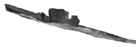
T o r p e d o G 7a |
|||
Drawings |
|||
 |
|||
Fly leafs 1 to 18 incorporated. |
|||
Published by the Torpedo Trials Institute |
|||
Eckernförde, September 1941. |
|||
| Navy Official Instruction Number | |||
C o n t e n t s |
||||||||||||||||||||||||||||||||||||||||||||||||||||||||||||||
|
||||||||||||||||||||||||||||||||||||||||||||||||||||||||||||||
Click on the thumbnails below to view a full sized plate and translated key
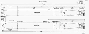 |
Plate 1 - Torpedo G7a | |
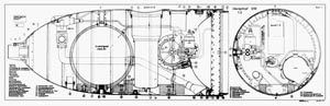 |
Plate 3 - Exercise head (1210) | |
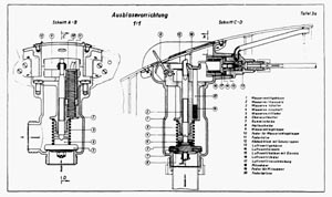 |
Plate 3a - Blowing mechanism | |
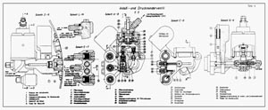 |
Plate 4 - Starting and pressure regulating valve | |
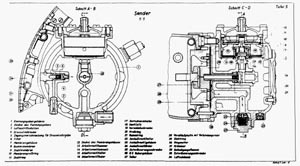 |
Plate 5 - Noise generator | |
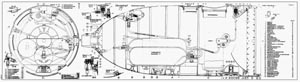 |
Plate 6 - Exercise head (1215) | |
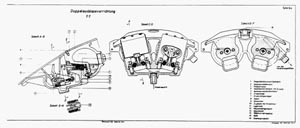 |
Plate 6a - Double blowing mechanism | |
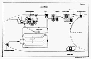 |
Plate 6c -Schematic diagram | |
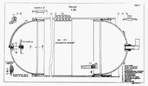 |
Plate 7 - Air flask | |
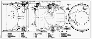 |
Plate 8 - Fuel oil and water chamber with air flask shutoff
valve, pressure equalizer and oil tank for the engine |
|
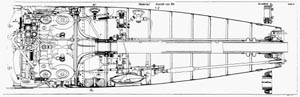 |
Plate 9 - After body view from port | |
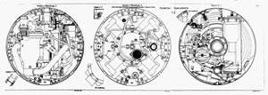 |
Plate 10 - After body cross-section | |
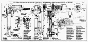 |
Plate 11 - Filling and shut off valve with water check valve for GA, regulating valve with oil tank, engine shutoff and over-pressure regulating valve | |
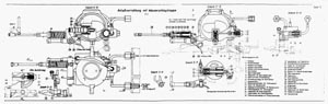 |
Plate 12 - Starting gear with water flap valve | |
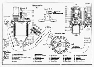 |
Plate 13 - Combustion pot | |
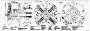 |
Plate 14 - Engine | |
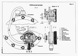 |
Plate 15 - Cooling water pump | |
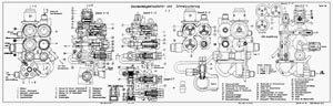 |
Plate 16 - Speed setting gear and safety fuze | |
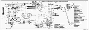 |
Plate 17 - Stop and rudder locking gear with lubrication oil flow interrupter | |
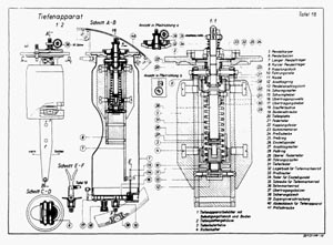 |
Plate 18 - Depth control mechanism | |
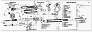 |
Plate 19 - Regulating nozzle (service air input), steering engine, depth rudder linkage | |
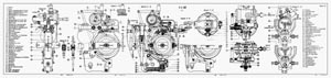 |
Plate 20 - Gyroscope VIII | |
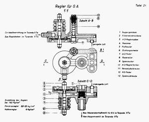 |
Plate 21 - Reducing valve for gyroscope | |
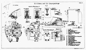 |
Plate 22 - Gyroscope-assembly and gyroscope-steering linkage | |
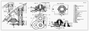 |
Plate 22a - Angle-setting device | |
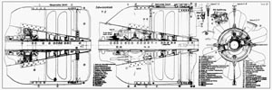 |
Plate 23 - Tail piece | |
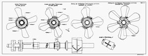 |
Plate 24 - Plate 24: Forward drive propeller from aft, forward and aft drive propellers seen from aft, relationship of the four-bladed drive propellers and crank to each other at "ready for shooting" position, relationship of the six-bladed drive propellers and crank to each other at "ready for shooting" position | |
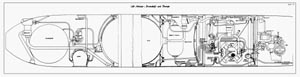 |
Plate 25 - Air, water, fuel, and oil paths | |
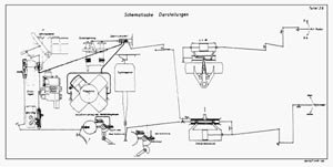 |
Plate 26 - Schematic Diagrams |
Keywords |
||||||||||||||||||||||||||||||||||||||||||||||||||||||||||||||||||||||||||||||||||||||||||||||||||||||||||||||||||||||||
|
||||||||||||||||||||||||||||||||||||||||||||||||||||||||||||||||||||||||||||||||||||||||||||||||||||||||||||||||||||||||