 |
Cover - Sketchbook for the Technical Personnel for U-boat Type VII C, Volume M - Ship and Machinery Operation | |
 |
Regulations | |
 |
Title Page | |
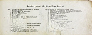 |
Table of Contents | |
 |
Change Page | |
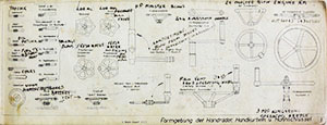 |
Plate 1: Summary of installed hand wheels, hand cranks, and spanners This plate does not have a Key so the David Taylor reproduction with English translations from the U-570 Sketchbook was included |
|
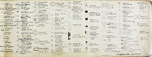 |
Plate 2: Symbols used This plate does not have a Key so the David Taylor reproduction with English translations from the U-570 Sketchbook was substituted |
|
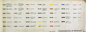 |
Plate 3: Color identification of piping |
|
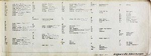 |
Plate 4: Abbreviations used | |
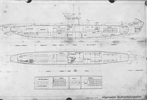 |
Plate 5: General arrangement of vessel This plate is missing from the color copy of the Design Book so the black and white version from U-570 was substituted |
|
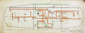 |
Plate 6: Drainage and trim sistem | |
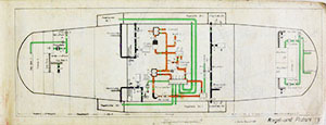 |
Plate 7: Regulating and torpedo compensating system | |
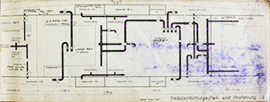 |
Plate 8: Fuel oil venting, sounding and test piping (longitudinal section) | |
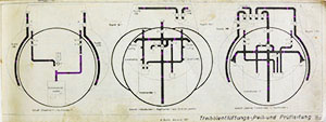 |
Plate 8A: Fuel oil venting, sounding and test piping (cross-sections) | |
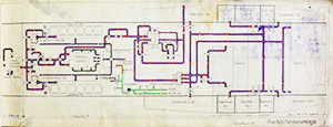 |
Plate 9: Fuel onboarding and delivery system | |
 |
Plate 10: Fuel oil compensating system (circulating water under pressure) | |
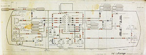 |
Plate 11: High pressure air system | |
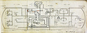 |
Plate 12: Low pressure or service air system | |
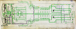 |
Plate 13: Cooling-water system and anti-corrosion oil-circulating system; for boatss with Krupp engines
|
|
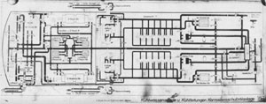 |
Plate 13A: Cooling-water system and anti-corrosion oil-circulating system; for boatss with MAN engines This plate is missing from the color copy of the Design Book so the black and white version from U-570 was substituted |
|
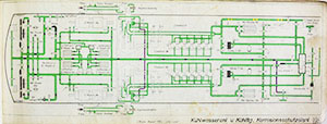 |
Plate 13B: Cooling-water system and anti-corrosion oil-circulating system; for U93-U97 The key for this plate is missing from the color copy of the Design Book so the black and white version from U-570 was substituted |
|
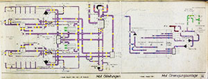 |
Plate 14: (Left) Engine lubricating oil system, (Right) lubricating oil storage, sump and purifying system, for Krupp engines | |
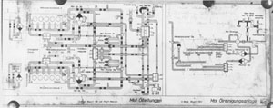 |
Plate 14A: (Left) Engine lubricating oil system, (Right) lubricating oil storage, sump and purifying system, for MAN engines | |
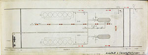 |
Plate 15: Engine starting air and induction air (for Krupp engines) | |
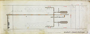 |
Plate 15A: Engine starting air and induction air (for MAN engines) | |
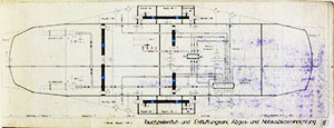 |
Plate 16: Flooding, venting, low pressure exhaust gas and emergency blowing systems | |
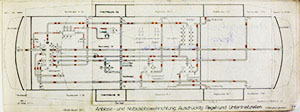 |
Plate 17: Blowing and emergency blowing systems for ballast, regulating and negative buoyancy tanks | |
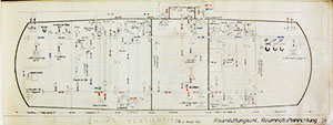 |
Plate 18: Compartment ventilating system, emergency ventilating installation | |
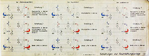 |
Plate 19: Switching diagrams for the compartment ventilation system | |
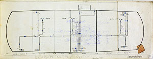 |
Plate 20: Oxygen system | |
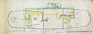 |
Plate 21: Fresh water, wash water, waste and sanitary systems | |
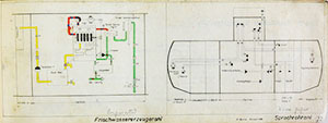 |
Plate 22: (Left) Evaporating and distilling system; (Right) voice tube system | |
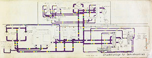 |
Plate 23 Hydraulic system for operating periscopes | |
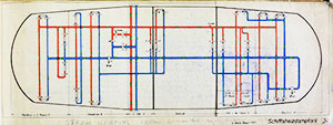 |
Plate 24: Ship's steam heating system | |
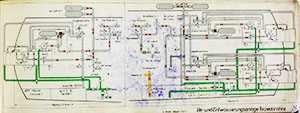 |
Plate 25: Torpedo tube firing, venting, flooding and drainage systems | |
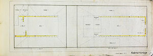 |
Plate 26: Lime-water (acid neutralizing) system (for battery compartments) | |
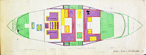 |
Plate 27: Diagram of bunkers, containers and tanks | |
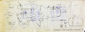 |
Plate 28: Flooding and venting system for ballast and buoyancy tanks | |
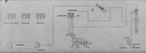 |
Plate 29: Air starting gear for Krupp engines | |
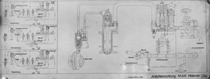 |
Plate 29A: Air starting gear for MAN engines | |
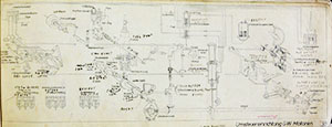 |
Plate 30: Reversing gear for Krupp engines | |
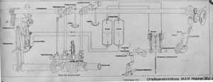 |
Plate 30A: Reversing gear for MAN engines | |
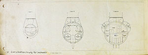 |
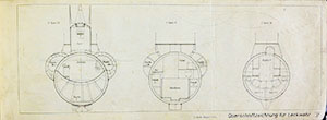
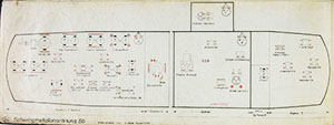
Plate 31: Cross-sectional diagrams for leak control | |
 |
||
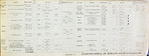 |
Plate 32: Hoses and their applications | |
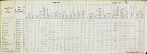 |
Plate 33: Pumping diagram | |
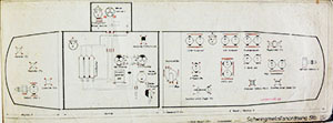 |
Plate 34: Vibration and noise absorbing mountings, starboard and port | |
 |
||