CONFIDENTIAL |
|||||||||||||||||||||||
September 28, 1941. |
|||||||||||||||||||||||
REPORT ON THE GERMAN SUBMARINE OF THE |
|||||||||||||||||||||||
U-570 CLASS CAPTURED BY THE BRITISH |
|||||||||||||||||||||||
IN AUGUST 1941 |
|||||||||||||||||||||||
|
|||||||||||||||||||||||
|
|||||||||||||||||||||||
- 1 - |
|||||||||||||||||||||||
TABLE OF CONTENTS |
||||||||||||||||||||||||||||||||||||||||||||||||||||||||||||||||||||||||||||||||||||||||||||||||||||||||||||||||||||||||||||||||||||||||||||||||||||||
| ||||||||||||||||||||||||||||||||||||||||||||||||||||||||||||||||||||||||||||||||||||||||||||||||||||||||||||||||||||||||||||||||||||||||||||||||||||||
- 2 - |
||||||||||||||||||||||||||||||||||||||||||||||||||||||||||||||||||||||||||||||||||||||||||||||||||||||||||||||||||||||||||||||||||||||||||||||||||||||
PART I |
||
SECTION I - A . . . . . . . . . . . . . . . . . . . . . . . . . . . . . HISTORICAL: |
||
It is believed that the submarine was commissioned in May or June, 1941. According to the legend on the general arrangement plan, Enclosure (A), at least twenty-four submarines of this type were built or projected; viz |
||
U-551 to 562 and |
||
U-563 to 574 |
||
A brief story of the capture, beaching, and salvage of the submarine with pertinent comments of eye witnesses and others familiar with these occurrences follows: |
||
Sometime during the afternoon of 26 or 27 August, a British aircraft of the Hudson type picked up on its ASV (anti-surface vessel) radio echo ranging equipment an indication of the presence of a ship on the surface at a distance of approximately fourteen (14) miles. The plane proceeded towards the indicated vessel - assuming that it was an enemy ship. It was the German submarine reported on herein. At the time of sighting by the plane the submarine had dived - or was diving and had reached periscope depth by the time the plane arrived directly over it. The plane dropped a stick of four (4) two hundred and fifty (250) pound depth charges on the spot, set to explode at 50 foot depth. (The Captain of the U-570 claimed that he heard the plane before he saw it, and dived on hearing contact rather than on sight contact). |
||
Shortly after dropping the depth charges, the submarine surfaced and remained in the low buoyancy condition. The plane |
||
- 3 - |
||
circled the submarine and machine-gunned it. Very soon a white flag was raised on the submarine. British Icelandic authorities were notified of the surrender and they immediately despatched surface vessels and a relief aircraft to the scene. |
||
It was approximately twelve hours before the surface vessels arrived on the scene. During the night an aircraft patrol was maintained over the submarine. H.M.S. BURWELL (Ex U.S.S. LAUB) arrived on the scene early in the morning. Four trawlers had arrived on the scene just prior to the arrival of H.M.S. BURWELL. |
||
Upon arrival of H.M.S. BURWELL, that vessel circled the submarine and sized up the situation. The submarine appeared to be very low in the water. The first message received from the submarine was. - "Will you take off our crew?". to which the BURWELL replied, - "Blow main ballast tanks and send your crew below". No reply was received and no action was taken by the German crew to blow main ballast tanks or go below. |
||
Another message was sent, - "Do not attempt to throw any papers or books overboard and do not attempt to scuttle". An answer was received to this message. - "What does scuttle mean?" |
||
Very shortly after the above message was received the following message was received from the submarine, - "Will you take off our crew, we are sinking": to which the commanding officer, H.M.S. BURWELL replied, - "Blow fuel overboard". |
||
Since no action was taken to blow main ballast tanks or to blow fuel and since no member of the crew was observed to go below, the commanding officer of H.M.S. BURWELL opened fire on the submarine with a burst from one fifty caliber machine gun. Members of the |
||
- 4 - |
||
crew of the submarine were wounded and others rushed below decks. Ballast tanks and fuel tanks were then blown. (Air to the fuel tanks was not completely shut off until a boarding party boarded the submarine. Whether this was due to fright or was a deliberate attempt to deplete the air supply is not known). The reason that no attempt to board the submarine had been made up to this time was the bad weather. A very high sea wa running which, however, was moderating. |
||
After blowing tanks the submarine signaled, - "Will you take off my wounded"; to which BURWELL replied, - "Yes". After two unsuccessful attempts by the BURWELL to float a raft to the submarine one of the trawlers succeeded in doing so. The first persons to leave the submarine were its officers and not the wounded. A total of six wounded were later removed from the submarine. |
||
In view of the better maneuvering qualities of the trawlers in the still heavy sea after several attempts to float a line to the submarine by H.M.S. BURWELL, one of the trawlers was directed to take the submarine in tow. |
||
The removal of the entire crew from the submarine was completed about fifteen hours after the arrival of the surface ships on the scene. |
||
The commanding officer of H.M.S. BURWELL had not planned nor did he desire to remove any of the crew other than the wounded from the submarine until he had forced them to place the ship in as stable and sea-worthy a condition as possible. The enthusiastic, but somewhat untimely, interference of the trawlers resulted in loss of control of the situation by the commanding officer of H.M.S. BURWELL. |
||
- 5 - |
||
This interference by the trawlers very nearly resulted in the loss of the submarine and did undoubtedly result in the necessity for early beaching of the submarine. |
||
While the German crew was being removed from the submarine members of the trawler crew had succeeded in making the tow line fast and had also done some rather superficial and unintelligent inspection below decks. This first boarding party found the after control room door closed. They opened the door carefully and found considerable water in the engine room. This boarding party closed the after control room door and reported the engine room to be flooding, and also reported chlorine gas in the after battery compartment. Both of these statements were in error. There was never any evidence of chlorine gas in the submarine, in spite of the fact that approximately forty (40) jars were cracked as a result of the depth charging, and the water in the engine room was the result of a deliberate removal of a strainer bonnet during the early period of the surrender, but which had been replaced when the German crew realized that there were no surface ships present to rescue them. |
||
Also, during the period of removal of the German crew, a Norwegian aircraft flew over the submarine and dropped two small bombs nearby. The bombs did no damage nor did they cause any casualties. This plane was warned off by the commanding officer of H.M.S. BURWELL, but only after considerable discussion as to who was going to be allowed to sink the submarine. |
||
The initial intelligent but rather hurried examination of the submarine conducted by officers and men of submarine experience revealed the following conditions with regards to damage and stability: |
||
- 6 - |
||
1. All lights were out. |
||
2. The engine room was flooded to the floor plates. |
||
3. Numerous water gauge glasses were broken with small streams of water entering the ship. |
||
4. Many instrument faces had been deliberately smashed by the crew. The faces of all depth gauges except the one on the forward torpedo room were smashed, and the numerals were scraped off the dials of the smashed gauges. |
||
5. The ship was slightly down by the bow and listed slightly to port. |
||
6. About forty (40) battery jars were cracked. (The number actually cracked was not definitely determined until several days later). |
||
7. All compartments had been deliberately cluttered up with all sorts of debris including clothes, food, spare parts, etc. |
||
8. Some vents were not completely closed. |
||
9. Air banks were almost completely empty and air was still escaping to the fuel tanks. |
||
Sometime during the period of the removal of the German crew and initial examination of the ship, (exact time unknown) British intelligence officers from Iceland arrived; and thinking that the ship would undoubtedly sink very soon, they started a very hurried and rather unorganized examination of the ship and also began to remove all books, papers, plans, etc. During this period certain officers and men with submarine experience from the several ships that were present were engaged in activities to make the ship stable and sea-worthy. |
||
- 7 - |
||
The commanding officer of H.M.S. BURWELL decided that the proper and immediate procedure was to tow the submarine towards the nearest beach as quickly as possible so that the ship could be beached if necessary. This was done. |
||
During the period of towing, which was about twenty-four hours, the tow line parted. Another trawler took up the tow, but this time the submarine was towed stern first. During the period of towing it was noted that the draft of the submarine was gradually increasing and the decision was made to beach the ship as soon as possible. It had been planned to beach the ship bows on and to hold her in that position with appropriately located anchors. However, upon reaching the selected beach, the ship beached herself prematurely broadside to. |
||
After beaching and after arrival of a nucleus crew consisting of an experienced submarine commanding officer and several experienced enlisted men, a more detailed and careful examination was made: whereupon it was decided that the damage that had been done to the submarine was relatively minor, and that the ship should be refloated as soon as possible in order to avoid any further damage from the seas. |
||
Salvage personnel and equipment were immediately despatched from Iceland and within a day or so the ship was floated off and towed into Hvalfjordur, Iceland, and secured alongside H.M.S. HECLA, where action was immediately started to place the ship in an operating condition. |
||
During the period that the submarine was on the beach further damage was done, to the extent that the bow planes were rendered inoperative and the twin vertical rudders sprung out of alignment, resulting in difficult operation of same. No other damage was done as a result of the beaching in so far as could be determined. |
||
- 8 - |
||
Slow leaking of M.B.T. No. 3 was found to be due to a crack in the plating of this tank just below the saddle tank. The engineer officer of the tender HELCA stated that this crack was about 3 inches long and not at a weld. Leakage was stopped by installing an external patch plate over the crack. The patch plate was secured by studs shot into the tank plating by an underwater stud gun. It is not known whether this crack was due to the depth charge attack or not. |
||
When the ship was boarded the bases of lighting system fuze holders were found to be broken, and the fuses had dropped from the clips. |
||
One reason why this submarine was captured was the very fortunate condition which resulted in the protracted retention of the crew aboard the submarine. Actually the untimely interference of the trawler in removing the officers from the submarine, thus causing the commanding officer of H.M.S. BURWELL to lose control over the situation, very nearly resulted in the actual loss of the submarine. |
||
It appears that the surrender of the submarine was due entirely to the panicky and frightened condition of the personnel. This was due to their inexperience and lack of knowledge of the details of their ship - because the ship was not severely damaged and might have been able to escape during the night while guarded only by planes, if the lighting situation had been corrected as the main engines were fully and completely operative - in fact, the ship was quite capable of being operated submerged. |
||
The submarine has been operated on the surface by its British crew and was fully prepared to sail for the British Isles on 25 September, 1941. Due to the inoperative condition of the bow planes |
||
- 9 - |
||
and the poor condition of the battery it was not planned to operate the ship submerged. All preparations had been made on 25 September for moving the submarine to the British Isles. The exact sailing date is not known to the observers. |
||
- 10 - |
||
SECTION I - B . . . . . . . . . . . . . . . . . . . . . . . . . . . . . CIRCUMSTANCES OF INSPECTION: |
||
The observers sailed from Greenloch, Scotland, on 18 September, 1941, in H.M.S. BULLDOG, under orders to proceed to Iceland for the specific purpose of inspecting the captured German submarine; and , after completion of the inspection, to report to SOPA, U.S.N., for transportation to a port in the United States or Canada; and, finally to report to the Chief of Naval Operations, Washington, D.C. |
||
The observers arrived in Iceland at 2115, on 22 September, 1941, reported to SOPA, Admiral Munroe, U.S.N., in U.S.S. NEW MEXICO, at 0800, 23 September, 1941. After reporting to SOPA, the observers proceeded to H.M.S. HECLA and reported to the commanding officer of that ship under whose care and supervision the captured U-boat had been placed. The U-boat was alongside H.M.S. HECLA at the time. The commanding officer, H.M.S. HELCA, directed Lieutenant Colvin, R.N., acting commanding officer of the captured U-boat, to see that all facilities were made available to the inspecting officers. |
||
The photographs, Enclosure (C) and the photographic reproductions, Enclosure (A) and (B) were obtained with the invaluable assistance of Ensign R. O. Anderson, Jr., U.S.N., U.S.S. NEW MEXICO. |
||
- 11 - |
||
PART II |
||
TECHNICAL: |
||
SECTION II - A . . . . . . . . . . . . . . . . . . . . . . NOTES ON SOURCES OF INFORMATION: |
||
It is understood that, when the U-570 was captured, a complete set of ship's plans were aboard; and, that they were removed from the ship by British intelligence officers and sent to the Admiralty prior to the time of the inspection reported herein. Reproductions of these plans will therefore undoubtedly be forwarded to the Navy Department by the Naval Attaché, London. |
||
A general arrangement plan of the ship and a booklet of diagrams of systems were available on board. These were photographed. Although the photographs are too small for convenient use, a bound set of prints of the original negatives is forwarded herewith for record and reference purposes. The negatives are in the hands of the writers (28 September, 1941) and enlargements will be obtained through the facilities of the David Tay;or Model Basin upon their arrival in Washington. |
||
Permission was obtained from the British captain of the submarine to take photographs of the ship. Prints are forwarded herewith as Enclosure (C). The photographs were taken by a U.S. Navy photographer. At the request of the Captain of the submarine the negatives were left with the captain of H.M.S. HECLA for transmittal to the Admiralty. It was considered important to obtain a set of photographs prior to departure of the ship for the United Kingdom in view of the hazards of the passage. The Department may be expect to receive complete detailed information on all features of the submarine subsequent to the detailed examination by Admiralty and U.S. specialists to which all installation therein will undoubtedly be subjected upon arrival of the submarine in the United Kingdom. |
||
- 12 - |
||
SECTION II - B . . . . . . . . . . . . . . . . . . . . . . HULL AND FITTINGS: |
|||||||||||||||||||||||||||||||||||||||||||||||||||||||||||||||||||||||||||||||||||||||||||||||||||||||||||||||||
CONTENTS |
|||||||||||||||||||||||||||||||||||||||||||||||||||||||||||||||||||||||||||||||||||||||||||||||||||||||||||||||||
| |||||||||||||||||||||||||||||||||||||||||||||||||||||||||||||||||||||||||||||||||||||||||||||||||||||||||||||||||
- 13 - |
|||||||||||||||||||||||||||||||||||||||||||||||||||||||||||||||||||||||||||||||||||||||||||||||||||||||||||||||||
SECTION II - B - 1. . . . . . . . . . . . . . . . . . . . . . GENERAL DESCRIPTION: |
||
(a) GENERAL PARTICULARS: |
||
TYPE: Saddle tank construction. |
||
LENGTH OVERALL: 220 feet (plus or minus 1/2 foot). |
||
DISPLACEMENT: Roughly calculated to be about ______ tons (See calculation p. hereof) in surface condition diving trim (M.B.T.'s and fuel ballast tanks empty). |
||
MAXIMUM DIAMETER OF INNER HULL: About 184-3/8" inches. (Note: This dimension is not exact. It was scaled on a 1:50 scale drawing). No clear space was available for actual measurement of maximum diameter. Maximum diameter obtains only for the length of the control room. A vertical diameter was, however, measured at the forward end of the engine room and checked within one inch of the diameter at this same location as scaled from the 1:50 drawing. |
||
TEST DEPTH: Not known. A depth gauge in the forward torpedo room; which, unlike the one in the control room, had not been smashed by the surrendering German crew, is graduated from zero to 200 meters - 656 feet. (See Section II-B-2 for thickness of inner hull plating and frame spacing). |
||
MAXIMUM SPEED (Surface) - - - - - - - - - - 17.8 knots |
||
MAXIMUM SPEED (Submerged) - - - - - - - - 8 knots |
||
TOTAL FUEL OIL CAPACITY: |
||
Internal fuel oil tanks No's 1 & 2 - - - - 18,680 U.S. Gals. |
||
F.B.T.'s No's 2 & 4 - - - - - - - - - - - 12,990 U.S. Gals. |
||
______ |
||
| TOTAL - - - - - 31,670 U.S. Gals. | ||
- 14 - |
||
September 28, 1941 |
||||||||||||||||||||||||||||||||||||||||||||||||||||||||||||||||||||||||||
U-570 |
||||||||||||||||||||||||||||||||||||||||||||||||||||||||||||||||||||||||||
Summary of Calculation of Displacement |
||||||||||||||||||||||||||||||||||||||||||||||||||||||||||||||||||||||||||
Note: Approximation only. Work based on small scale photo of plan. |
||||||||||||||||||||||||||||||||||||||||||||||||||||||||||||||||||||||||||
|
||||||||||||||||||||||||||||||||||||||||||||||||||||||||||||||||||||||||||
- 14a - |
||||||||||||||||||||||||||||||||||||||||||||||||||||||||||||||||||||||||||
ARMAMENT: |
|||||||||||||||||||||||
4 in No. 21" internal bow tubes. |
|||||||||||||||||||||||
1 in No. 21" internal stern tube. |
|||||||||||||||||||||||
1 in No. 88 m.m. L.A. gun. |
|||||||||||||||||||||||
1 in No. 20 m.m. A.A. gun. |
|||||||||||||||||||||||
TORPEDOES: |
|||||||||||||||||||||||
5 in No. in tubes. |
|||||||||||||||||||||||
6 in No. in F.T.R. |
|||||||||||||||||||||||
1 in No. in A.T.R. |
|||||||||||||||||||||||
2 in No. in outboard stowage tanks. |
|||||||||||||||||||||||
Total - - - - - - - - - 14 torpedoes. |
|||||||||||||||||||||||
(Note: Two (2) of the six (6) spare torpedoes in F.T.R. were apparently "carried in excess"). |
|||||||||||||||||||||||
ACCOMODATIONS: |
|||||||||||||||||||||||
One commanding officer's bunk. |
|||||||||||||||||||||||
Three wardroom bunks. |
|||||||||||||||||||||||
Four warrant officer's or C.P.O. bunks. |
|||||||||||||||||||||||
| Eight petty officer's bunks. | |||||||||||||||||||||||
| Twelve crews bunks in F.T.R. | |||||||||||||||||||||||
| British Officers stated that the total crew of the submarine when taken off (including both officers and men) was "about 50". The writers believe "about 40" to be more nearly correct. This figure can be and should be checked through the Naval Attaché, London. | |||||||||||||||||||||||
| (b) TABLE OF TANK CAPACITIES: | |||||||||||||||||||||||
|
|||||||||||||||||||||||
- 15 - |
|||||||||||||||||||||||
| |||||||||||||||||||||||||||||||||||||||||||||||||||||||||||||||||||||||||||||||||||||||||||||||||||||||||||||||||||||||||||||||||||||||||
(c) MATERIALS AND WORKMANSHIP: |
|||||||||||||||||||||||||||||||||||||||||||||||||||||||||||||||||||||||||||||||||||||||||||||||||||||||||||||||||||||||||||||||||||||||||
In general the ship is beautifully built. Workmanship and finish throughout the ship appears equal to the best U.S. submarine practice. There is no outstanding evidence of use of substitute materials. |
|||||||||||||||||||||||||||||||||||||||||||||||||||||||||||||||||||||||||||||||||||||||||||||||||||||||||||||||||||||||||||||||||||||||||
- 16 - |
|||||||||||||||||||||||||||||||||||||||||||||||||||||||||||||||||||||||||||||||||||||||||||||||||||||||||||||||||||||||||||||||||||||||||
SECTION II - B - 2. . . . . . . . . . . . . . . . . . . . . . STRUCTURE: |
||
(See general arrangement plan Enclosure (A) and photographs Enclosure (C)) |
||
(a) The submarine is of the saddle tank type. The inner hull is cylindrical throughout the length of the control room and tapers toward the ends of the ship from the ends of the control room. The whole structure is welded construction with the exception of the superstructure side plating which is riveted, and portable plates in the top of the inner hull. Inner hull frames are internal and the webs of the bulb tee frames are connected to the I.H, plating by continuous welds on both sides of the webs of the frames. |
||
(b) SCANTINGS: |
||
Inner hull maximum diameter - about 184 - 3/8 inches. |
||
Frame spacing 23 - 1/2 inches. |
||
Thickness of I.H. plating at max. diameter - probably 7/8 of an inch. (The thickness was gauged at 7/8" at the A.T.R. loading hatch. A thickness of 3/4" was gauged at the F.T.R. loading hatch. A drill test in the control room started by the British had been abandoned before perforation, and a drill test by the observers was discouraged as the ship was standing by to sail on short notice. There were no exposed I.H. plate edges in the control room). |
||
Quality of I.H. plating: Not known. The chief engineer of H.M.S. HECLA stated that the plate was difficult to drill and he judged it to be a very high strength weldable steel. Drilling had been disposed of. |
||
Pressure hull frames are 7 - 3/4" deep bulb tees. The fore and aft dimension of the bulb is 2 - 3/8". |
||
- 17 - |
||
Main Divisional Bulkheads: The control room bulkheads are the only main divisional bulkheads in the ship which are built to withstand great pressure. They are dished bulkheads of 3/4" plate. They are peripherally tee welded where they meet the I.H. plating to a circumferential strap welded to the I.H. plating. Circular dished plate doors are fitted in the two C.R. bulkheads. The door locking arrangement is an interrupted flange ring mounted on the circular door frame. With the door on its seat, the locking ring may be rotated by a lever operated pinion which engages a rack on the locking ring. Rotation of the ring moves parts of the ring over peripheral lugs on the door and forces the door on to its seat. The diameter of the clear opening through the door is 31 - 3/4". |
||
Other main divisional bulkheads are made of about 15# plate, and 21 - 5/8" X 57" doors secured by six hand dogs, are provided in these bulkheads. |
||
End bulkheads are steel castings. |
||
- 18 - |
||
SECTION II - B - 3. . . . . . . . . . . . . . . . . . . . . . HULL FITTINGS: |
||
Galvanized floor plates are fitted in C.R., E.R. and A.T. & M.R. |
||
Net cutters, shown on the enclosed plans, are not fitted in the ship captured. |
||
Housing bitts and deck cleats are hollow welded construction. |
||
Windlass and capstan are operated by an air motor installed in the bilge between the two lower torpedo tubes in F.T.R. Wood decking is fitted on the superstructure. |
||
External torpedo stowage tanks are apparently made of a copper nickel alloy. |
||
Plans indicate a boat stowed on its side on the port side forward, but no boat was aboard the submarine when inspected. |
||
In each battery tank a trolley supported platform is provided which can be moved manually from end to end of the tank by a man lying thereon; and from which inspection of cells and battery watering may be accomplished. |
||
One anchor is carried. |
||
Pressure hull hatches are single action had wheel locking type with three lugs. |
||
- 19 - |
||
SECTION II - B - 4. . . . . . . . . . . . . . . . . . . . . . FLOODING AND VENTING: |
||
(a) There are three M.B.T.'s fuel-ballast tanks, a stern buoyancy tank and a bow buoyancy tank. (See Section II-B-1 for tank capacities). In this report tanks are numbered from aft forward. The middle main ballast tank is apparently constructed as a safety tank. |
||
(b) FLOOD VALVES are fitted in M.B.T. No. 3 in fuel-ballast tanks. (see Plan No. 28). M.B.T. No. 3 is directly below the C.R. flat and within the strength hull. M.B. Tanks No's 1 and 5 are open to the sea through flood openings in their bottoms. Flood valves are manually operated by tee wrenches or cranks used on the ends of operating gear shafting extending into working spaces of the pressure hull. (Areas of flood valve are shown on Plan No. 28). |
||
(c) VENT VALVES of M.B.T.'s and Fuel-Ballast Tanks are manually operated from the control room. The vents of bow and stern buoyancy tanks are operated manually by hand wheels in the forward and after torpedo rooms respectively. Vent pipes from Fuel-Ballast Tanks No. 2 and No. 4 starboard lead to a common master vent valve abreast and on the conning tower. Vent pipes from Fuel-Ballast Tanks No. 2 and No. 4 port lead to a similar master vent valve on the port side. Vent ducts from M.B.T. No. 3 starboard and port lead from openings in the I.H. into and through the regulating tanks which are adjacent to M.B.T. No. 3. Emergency vent valves are fitted on the lower ends of these ducts at the I.H. These emergency vent valves are operated manually from the control room by tee wrenches. The master vent valves of Fuel-Ballast Tanks No's 2 and 4 and the vent valves of M.B.T. No. 3 are quick opening lever operated valves. Hand operated |
||
- 20 - |
||
emergency vent valves are provided in Fuel-Ballast Tanks No's 2 and 4 port and starboard. The vents of M.B.T's No's 1 and 5 are operated by hand wheels in the C.R. |
|||||||||||||||||||||||||||||||||||||||||
Separate vent pipes lead from the after ends of F.B.T.'s No. 2 Stbd & Port over the inner hull to vents on the middle line. Emergency vent valves are installed in these vent pipes. The vent valves at the top of the inner hull are controlled by a single hand wheel in the control room. (See Plan no. 16). |
|||||||||||||||||||||||||||||||||||||||||
Certain accessible vent valves were measured to obtain data for calculating the ratios of tank volumes to vent valve areas. These data are: |
|||||||||||||||||||||||||||||||||||||||||
|
|||||||||||||||||||||||||||||||||||||||||
(Note: This vent is an outward opening hinged type vent. All others are inward opening. It was closed and the clear opening could not be measured. The overall diameter of the valve was 22" (diameter of clear opening probably about 17").). |
|||||||||||||||||||||||||||||||||||||||||
(d) BLOWING: Main ballast tanks and fuel ballast tanks may be blown from the tank blowing manifold in control room. Supply to this blowing manifold from the high pressure flask manifold is manually |
|||||||||||||||||||||||||||||||||||||||||
- 21 - |
|||||||||||||||||||||||||||||||||||||||||
controlled by hand wheel (See Photograph No. 20). |
||
No low pressure blowers are installed. Arrangements are provided for low pressure blowing by engine exhaust gases. A pipe connection to the exhaust system outside of the hull leads forward to a manifold outside of the hull in way of the control room; and exhaust gases may be admitted to ballast tanks by operation of individual external valves from within the control room. (See note under Photograph No. 20). Admission of exhaust gases to this low pressure blowing system is controlled by a valve in the exhaust system outside the inner hull which is operated by a hand wheel in the engine room. |
||
- 22 - |
||
SECTION II - B - 5. . . . . . . . . . . . . . . . . . TORPEDO TUBES AND TORPEDO STOWAGE: |
||
(a) TUBES: |
||
Four (4) - 21" internal tubes forward. |
||
One (1) - 21" internal tube aft. |
||
STOWAGE OF TORPEDOES: |
||
Six (6) in forward torpedo room. |
||
One (1) in after torpedo room. |
||
One (1) in external tank forward. |
||
One (1) in external tank aft. |
||
(b) Torpedo tubes (21") are bronze. Torpedo tube shutters are fitted in the bow. Bow caps are mechanically interlocked with the breech door locking ring operating gear. |
||
(c) Bubbleless firing is provided for by admission of impulse air behind a skirted piston which bears against the tail of the torpedo. (See Photograph No. 13). The length of travel of the piston was not determined. The edge of the skirt of the piston registers with a narrow rubber gasket on the inside face of the breech door. This is possibly a bumper for receiving the piston upon its return to the breech end of the tube due to external water pressure when the tube is vented after firing. |
||
The small hand wheel at the center of each breech door is so fitted that by turning it, its stem moves axially. The stem extends through the door and registers with an adjustable screw plug on the cross piece at the skirt end of the piston. It is believed that this arrangement is a means for slightly advancing the piston in the tube prior to firing to break the seal between the edge of the skirt of the piston and the piston buffer on the tube-side face of the breech door, in order to permit impulse air to pass to the rear of the skirt. |
||
- 23 - |
||
Arrangements are provided for setting gyro angles on loaded torpedoes. These arrangements are discussed under "Part II - D - ARMAMENT". |
||
The original design apparently contemplated the stowage of only four reload torpedoes in the forward torpedo room. The two found in the upper row were apparently "carried in excess". They were covered over with a temporary board deck. |
||
Strongbacks used for handling torpedoes are shown in the photograph of the forward torpedo room. These strongbacks can be moved across the ship on transverse overhead rails by chain drive. Falls supporting torpedoes can be moved along the strongbacks by operation of pinions on the fall blocks which engage with longitudinal racks on the upper outboard edges of the strongbacks. A multiplicity of holes in the web of the strongbacks, all carefully identified by legends, are provided; apparently as location points for the several manipulations of the strongbacks in handling torpedoes. |
||
The deck storage tanks are provided with trunions at one end and are held in place by drop bolts which engage lugs on the sides of the tanks. One end of the tank can be elevated sufficiently so that a torpedo stowed therein may be withdrawn up on deck and then passed below. |
||
- 24 - |
||
SECTION II - B - 6. . . . . . . . . . . . . . . . . . STEERING AND DIVING: |
||
(a) STEERING: |
||
Twin vertical rudders are fitted as shown on the general arrangement plan. The great depth of the rudders compared to their width is notable. The British captain of the submarine stated that the ship is remarkably handy, and handles well on the surface at low and at high speeds. (He had not operated the ship submerged). Fitting of the twin rudders was obviously a solution to the problem of avoiding interference between steering gear and the after torpedo tube. The ship may be steered by electric motor and by hand. The motor and gear box are located overhead in the after torpedo room. (See Photograph No. 33). A drive shaft extension forward from the gear box leads to the hand steering station, which is just forward of the air compressor as shown on the general arrangement plan. When not in use the hand steering wheel may be removed from its spindle and the vertical shaft swung out of the way to port (on the drive shaft extension as a center) and secured. When in place for hand steering the hand steering assembly is secured in place by portable struts. The writers witnessed satisfactory hand steering of the ship by one helmsman at speeds up to twelve knots using rudder angles up to 15 degrees. The rudders are apparently overbalanced. |
||
Selection of hand or power steering is controlled by a manually operated clutch in the steering motor gear box. The ship may be steered by power from the bridge, the conning tower, and the control room. A portable steering controller is provided which may be mounted on the bridge or in the control room. |
||
- 25 - |
||
Rudder angle indicators are graduated to 35 degrees. |
||||||||||||||||||||||||||||||||||||||
The steering motor and its attached gear box are hung on rubber (or equivalent) flexible sound proof mountings of the compression type. A flexible coupling is introduced in the transmission system immediately aft of the gear box. The coupling is made up with what appears to be a rubber disc between two steel flanges. |
||||||||||||||||||||||||||||||||||||||
Name plate data on the steering motor are: |
||||||||||||||||||||||||||||||||||||||
| ||||||||||||||||||||||||||||||||||||||
(b) DIVING GEAR: |
||||||||||||||||||||||||||||||||||||||
Bow and stern diving planes may be operated by electric motor or manually from the control room. Controllers in the control room are of the "grip-wrist-pressure" type. Clutching in or clutching out the electric diving plane clutches are operated by pressure from the service air system. |
||||||||||||||||||||||||||||||||||||||
The bow planes can not be rigged in. They are, however, located as low in the ship as possible. (See general arrangement plan). |
||||||||||||||||||||||||||||||||||||||
The short thick longitudinal section of the stern planes is notable. |
||||||||||||||||||||||||||||||||||||||
Careful attention has obviously been given to the shape of the rope guard and outboard bearing support castings of bow and stern rudders, and to the skeg. (See general arrangement plan). |
||||||||||||||||||||||||||||||||||||||
- 26 - |
||||||||||||||||||||||||||||||||||||||
Plane angle indicators are marked as follows: |
||||||||||||||||||||||||||||||||||||||||||
Bow planes: |
||||||||||||||||||||||||||||||||||||||||||
| ||||||||||||||||||||||||||||||||||||||||||
Stern Planes: |
||||||||||||||||||||||||||||||||||||||||||
| ||||||||||||||||||||||||||||||||||||||||||
Name plate data on the stern diving-plane motor are: |
||||||||||||||||||||||||||||||||||||||||||
| ||||||||||||||||||||||||||||||||||||||||||
Instruments at the Diving Station: |
||||||||||||||||||||||||||||||||||||||||||
Shaft R.P.M. indicators. |
||||||||||||||||||||||||||||||||||||||||||
Electrical rudder angle indicators. |
||||||||||||||||||||||||||||||||||||||||||
Mechanical rudder angle indicators. |
||||||||||||||||||||||||||||||||||||||||||
Deep-diving Buordon-tube type depth gauge (One in control room had been sabotaged but one in the forward torpedo room was graduated to 200 meters). |
||||||||||||||||||||||||||||||||||||||||||
| A closed end tube-type shallow-diving depth gauge. | ||||||||||||||||||||||||||||||||||||||||||
| Coarse reading in closed loop liquid, trim indicator graduated from plus 25 degrees to minus 20 degrees. | ||||||||||||||||||||||||||||||||||||||||||
- 27 - |
||||||||||||||||||||||||||||||||||||||||||
Fine reading closed loop liquid trim indicator graduated from plus 5 degrees to minus 5 degrees. |
||
The closed end tube type of depth gauge is graduated on one side of the glass tube from 5 to 18 meters under the legend "Tauchtiefe Uber Unfarkante Kiel" (Diving depth over under edge of keel). An outline, properly distorted vertically, of the transverse section of the submarine thru the attack periscope is engraved on the other side of the tube to show the location of the surface with respect to the structure with the attack periscope extended. (See Photograph No. 19). |
||
- 28 - |
||
SECTION II - B - 7. . . . . . . . . . . . . . . . . . TRIMMING SYSTEM: |
||||||||||||||||||||||||||||||
Capacities of forward trim, after trim and regulating tank amidships are given in tank capacity tables in Section II - B - 1. |
||||||||||||||||||||||||||||||
Plan No. 6 is a diagram of the trimming system. |
||||||||||||||||||||||||||||||
The trim pump and manifold is located in the control room. It is a geared motor driven reciprocating pump. |
||||||||||||||||||||||||||||||
Flow meters are installed in the trimming system. |
||||||||||||||||||||||||||||||
Name plate data on the trim pump are: |
||||||||||||||||||||||||||||||
| ||||||||||||||||||||||||||||||
Trim and drainage manifolds are cross connected. |
||||||||||||||||||||||||||||||
- 29 - |
||||||||||||||||||||||||||||||
SECTION II - B - 8. . . . . . . . . . . . . . . . . . DRAINAGE SYSTEM: |
||||||||||||||||||||||
The drain pump and drain manifold is located in the control room. |
||||||||||||||||||||||
Plan No. 6 is a diagram of the drainage system. |
||||||||||||||||||||||
Plan No. 33 is a schedule of pumps and their suction and discharge connections. |
||||||||||||||||||||||
The drain pump is a vertical motor driven four stage centrifugal pump. It is mounted on the after control room bulkhead. |
||||||||||||||||||||||
Name plate data on this pump are: |
||||||||||||||||||||||
| ||||||||||||||||||||||
- 30 - |
||||||||||||||||||||||
SECTION II - B - 9. . . . . . . . . . . . . . . . . . COMPRESSED AIR SYSTEMS: |
||||||||||||||||||||||||||||||
Maximum air flask pressure if 205 atmospheres. |
||||||||||||||||||||||||||||||
The flask supply manifold, the tank blowing manifold, and the service air manifold are located on the starboard side of the control room next abaft the diving station. Pressure to the tank blowing manifold is manually controlled by a master stop and throttling valve at the high pressure air connection to this manifold. (See Photograph No. 20). |
||||||||||||||||||||||||||||||
Pressure to the service air manifold is controlled by a two stage reducing valve which reduces the pressure from 205 atmospheres to 12 atmospheres. This valve is remarkably small and is apparently of the spring loaded type. THe British chief engineer of the boat stated that the reducing had been entirely satisfactory. |
||||||||||||||||||||||||||||||
Two high pressure air compressors are installed. Both are located about midlength of the M. & A.T. Room. One is a Krupp electric motor driven four stage reciprocating compressor. |
||||||||||||||||||||||||||||||
The name plate data of the driving motor are: |
||||||||||||||||||||||||||||||
| ||||||||||||||||||||||||||||||
The other high pressure compressor is a four stage horizontal, crankless diesel driven, double acting, opposed piston two cycle machine. (See Photograph No. 31). It bears the label "Junkers Motorenbau". Pistons are the only moving parts except valves. It |
||||||||||||||||||||||||||||||
- 31 - |
||||||||||||||||||||||||||||||
occupies a space about 6' - 10" long X 28" athwartships X 35" in depth. It has a separate exhaust system and outboard muffler. The writers witness operation of this machine. It was extremely noisy. |
||
Both machines work at 205 atmospheres. |
||
Among the uses of service air are: |
||
Whistle. |
||
Power for handling diving plane motor clutches. |
||
Power for engine clutch. |
||
Driving muffler valve grinding gear. |
||
Operation of windlass and capstan. |
||
Handling trimming water. |
||
- 32 - |
||
SECTION II - B - 10. . . . . . . . . . . . . . . . . . HYDRAULIC POWER SYSTEM: |
||||||||||||||||||||||||||||||
Plan No. 23 is a diagram of the hydraulic power system. |
||||||||||||||||||||||||||||||
The hydraulic power system is fitted solely for periscope operation: viz. hoisting both periscopes and training of the "fixed-height-of-eye" attack periscope. Two duplicate hydraulic power plants are installed with means for selecting the one to be operated. One is definitely a standby for the other. |
||||||||||||||||||||||||||||||
The hydraulic pumps are screw type pumps vertically mounted and driven by vertically mounted electric motors. |
||||||||||||||||||||||||||||||
The name plate data on the motors are: |
||||||||||||||||||||||||||||||
| ||||||||||||||||||||||||||||||
The power units are mounted on a steel frame foundation and rest on compression type rubber mountings. There are, however, no flexible connections in the pipes leading from the pumps; but generous curves are worked into these pipes. |
||||||||||||||||||||||||||||||
The supply tank is mounted in the control room just above the deck providing an almost negligible head of oil to the pump suctions. The tank is vented to the compartment. |
||||||||||||||||||||||||||||||
Three accumulators are provided in the system. They are cylinders about 13 inches in diameter and about 72 inches long. They are installed vertically and are apparently directly air loaded with air above the oil therein. Gauge marking (red mark) indicated system pressure to be 80 atmospheres. |
||||||||||||||||||||||||||||||
- 33 - |
||||||||||||||||||||||||||||||
Each pump motor is controlled by a sylphon-operated pressure switch connected to the supply tank. (Not to the high pressure side of the system). Pump operation is therefore controlled by the level of oil in the low pressure supply and return tank. |
||
The two periscope hoisting motors are also apparently screw type hydraulic units. They drive periscope hoisting winches. The winch for the altiscope is in the control room. The winch for the attack periscope is in the conning tower. |
||
The attack periscope training motor is also apparently a screw type unit. This mechanism of the training drive could not have been seen without some disassembly of the periscope housing. The direction of rotation of the attack periscope is controlled by foot stirrups mechanically connected to throttle valves. |
||
The hydraulic plant and the periscopes were operated for the writers. Except when the relief valves of the system function the system is practically noiseless and vibrationless. It appears that the British crew was not full acquainted with the proper operation of the system, as it is unreasonable to suppose that functioning of the relief valve should occur each time the accumulators are charged. The noise made by a relief valve is very great indeed and exactly similar to that made by a relief valve of a Waterbury Variable Speed Gear. It is probable that the proper total quantity of oil was not in the system with the result that the sylphon control switches did not properly control the hydraulic power plant motors. |
||
- 34 - |
||
SECTION II - B - 11. . . . . . . . . . . . . . . . . . PERISCOPES: |
||
(a) Two periscopes are installed; viz. - A periscope-altiscope with eye-piece in the control room and a "fixed-height-of-eye" periscope with eye piece in the conning tower. |
||
The control room periscope-altiscope has a large field and is referred to herein as the "lookout" periscope. The conning tower periscope is obviously normally the "attack" periscope, and is so referred to herein. |
||
(b) "Lookout" Periscope: |
||
The maximum diameter is 7.1 inches. |
||
The diameter at the top is about 4 inches. |
||
When raised the periscope extends about 8 feet above the top of the highest structure (the bridge enclosure). |
||
This periscope is raised and lowered by hoisting wires. |
||
The periscope winch is driven by a hydraulic motor. (See Section II-B-10). The periscope is trained manually by means of the usual handles. The hoisting mechanism of this periscope was not operative at the time of the inspection. |
||
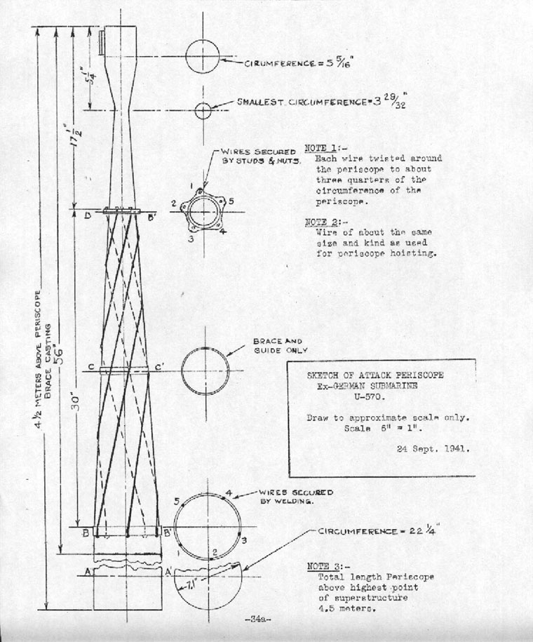
(c) "Attack" Periscope: |
||
The "attack" periscope was definitely the most impressive installation in the ship. It has elicited the greatest admiration from both British submarine officers and the observers. It is described by experienced submarine commanders as "the answer to an attack officer's prayer". This "fixed-height-of-eye" periscope is beautifully engineered. |
||
| The basic optical principles of this periscope installation are apparently the same as those of the "fixed-height-of-eye" periscope installed in our BASS, BONITA, and BARRACUDA soon after these ships were commissioned. | ||
- 35 - |
||
Mechanically the German installation is far superior to our early installation of this type in the BASS class. |
||
The small size of the top of the periscope itself, the small minimum diameter of the tapered section, and the spirally wound wire on the lower part of the tapered section should be noted. A sketch of the upper end of this periscope is bound herein. The apparent purpose of the wire spirally wound on the periscope is the reduction of periscope wake. Early test of the effectiveness of this device is recommended. |
||
The diameter of the cylindrical section of the periscope tube is 7.1 inches. When fully raised the periscope extends about 17 - 1/2 feet above the highest part of the structure of the ship. (This was scaled from a reduced scale drawing). |
||
The optical system is housed in a large cylindrical housing. (See Photograph No's 7 and 8). Housing and optics train together. The assembly may be trained by power supplied by a small screw type hydraulic motor mounted overhead in the conning tower, or manually by a hand wheel mounted on the housing at the operator's right hand. The periscope tube proper is raised and lowered by hoisting wires which lead to a winch which is driven by a screw type hydraulic motor. The winch is on the starboard side of the conning tower. |
||
The operator sits on a comfortable adjustable seat secured to the housing. His feel rest on foot cranks which control admission of oil to the training motor. Pressure applied on the right foot crank causes the assembly to rotate counter clockwise (looking down); and pressure applied on the left foot crank causes the assembly to rotate clockwise. |
||
- 36 - |
||
The periscope was operated by the observers. It operated smoothly and noiselessly by hydraulic power and manual control. Fine control of training speed is possible under both power or manual operation. The following other features are incorporated in the instrument: |
||
(1) Two powers 1.5 and 6.0 Corresponding fields are 380 and 90. |
||
(2) Prism tilting between angles of minus 15 to plus 20 degrees. |
||
(3) Direct reading range scale. |
||
(4) Ray filters. |
||
(5) A well illuminated azimuth of large diameter (approximately the diameter of the rotating housing) with vernier and bearing marker. |
||
(6) Means for electrically transmitting periscope bearing to the torpedo data computer. |
||
Periscope drying connections show in Photograph No. 7 labeled"Saugen". |
||
The outboard support for the periscope tube is shown in Photograph No. 7. |
||
There was no evidence of hull stuffing box leakage at either of the periscopes. |
||
All officers with whom this periscope were discussed agreed that it is the best built and most satisfactory periscope from a military point of view that they had ever seen, and they considered that the concessions in space and weight to accommodate it were fully justified. It is recommended that full constructional details of this instrument be obtained from the Admiralty, and that the manufacture of a U.S. prototype to this design be put in hand at the earliest possible date. |
||
- 37 - |
||
The following name plate data appeared on the periscope housing: |
||
" 1.5 X blc 380 |
||
6 X 90 |
||
1566 |
||
M IV/I |
||
Sta SRO/2 |
||
Nr 3122 " |
||
- 38 - |
||
SECTION II - B - 12. . . . . . . . . . . . . . . . . . FUEL OIL SYSTEM: |
||
Plans No's 8, 8a and 10 are diagrams of the fuel oil system. The system is a compensating system. Oil is forced to the fuel oil measuring tank by pressure from the engine cooling water circulating system. A hand pump is provided in the engine room which pump may be used to pump compensating water and move oil to the measuring tank. |
||
See Section II - B - 1 for capacities of all tanks. |
||
- 39 - |
||
SECTION II - B - 13. . . . . . . . . . . . . . . . . . VENTILATION AND AIR CONDITIONING: |
||
Outboard terminals of the ventilation system are rectangular openings (with screens over) in the side plating of the conning tower fairwater, just below the level of the bridge deck. |
||
One supply and one exhaust fan are installed with the usual cross connection for operating when submerged. |
||
Plan No. 18 is a diagram of the ventilation system. Plan No. 18 shows flow diagrams under the various possible conditions of operation of the ventilation system. |
||
The diameter of the ventilation pipes leading into the ship from the conning tower fairwater is approximately 9 - 3/4". |
||
(b) BATTERY VENTILATION: |
||
Battery exhaust ventilation is individual cell, manifolded, closed type, similar to current U.S. practice. Battery exhaust connects into ship's ventilation exhaust system. The main ducts of the exhaust manifold in the battery compartments appeared to be made of impregnated card board rather than rubber. U-tube manometer flow meters were installed. The British crew had been unable to make these function properly up to the time of the inspection. |
||
Flexible connections to the ship's ventilation exhaust system are provided in the forward and after torpedo room for use when charging batteries of electric torpedoes. A similar flexible connection is provided at the charging panel in the motor room which is installed for charging wet cell portable emergency lanterns. |
||
- 40 - |
||
(c) AIR CONDITIONING: |
||
Carbon Dioxide CO2 absorbent (apparently soda lime) is provided in flat cans with small circular "knock outs" top and bottom. Several cans may be seen on Photograph No. 32. When the purifiers are to be used, the circular "knock outs" are removed and the cans are inserted in rack manifolds connected to the suction side of the ventilation system. Air is drawn up through the bottom hole, through the CO2 absorbent into the ventilation system. One of the rack manifolds is shown in Photograph No. 28. |
||
Plan No. 20 is a diagram of the oxygen system. |
||
(d) ENGINE AIR INDUCTION: (See general arrangement plan) |
||
The outboard engine air induction intake is a rectangular duct at the after end of the bridge chariot inboard of and having one side in common with the outside plating of the chariot side. The top of the duct is at the level of the top of the chariot side plating. A manually operated outboard valve is fitted in this induction system in way of the control room. This valve is operated from the control room. The circular induction pipe which leads from the outboard valve to the hull valve at the forward end of the engine room is about 21 - 1/2 inches in diameter. The hull valve is operated manually from within the engine room. |
||
The general arrangement plan show the engine air intake system terminating just below the bridge deck. The working of the duct into the chariot was probably an alteration made to minimize shipping of water at high surface speeds in heavy weather. |
||
- 41 - |
||
SECTION II - B - 14. . . . . . . . . . . . . . . . . . SOUND AND THERMAL INSULATION: |
||
(a) SOUND INSULATION: |
||
Certain auxiliary machinery which may be operated submerged is mounted on compression type rubber mountings. This was specifically noted in the case of the steering motor and the hydraulic power plant. |
||
Link type rubber mats are provided on metal decks. |
||
It was noted that a number of auxiliaries were marked with an "X". These included diving plane motors and steering motors. It is likely that this marking designates machinery to be shut down and operation shifted to manual control under conditions requiring most quiet operation. |
||
No sound insulation of main motor mounting was noted. |
||
The friction type tail clutches are absolutely silent in operation when changing speed as well as when running at constant speed. |
||
(b) THERMAL INSULATION: |
||
No cork sheathing or cork paint was seen in the ship. |
||
Plywood or sheet metal sheathing is installed in officer's warrant (or C.P.O.) and petty officer's quarters, and part of the length of the F.T.R. in way of the crews bunks is sheathed. |
||
- 42 - |
||
SECTION II - B - 15. . . . . . . . . . . . . . . . . . SHOCK PROOFING: |
||
Certain heavy vertically mounted instruments and gauges are mounted on shear type rubber flexible mountings. However, the use of such mountings is not general. Sound powered telephones were so mounted as were several gauges noted. Decision to so mount seemed to be based on the mass of the instrument as compared to the ruggedness of its footings. It is understood (but unconfirmed by the writers) that the Germans have carried out depth charge tests on this class of submarine. Consequently decisions as to shock mountings have probably been based on experimental results. There was no evidence of failure of gauges, other than glass tube type, due to the successful attack on the submarine. Bases of lighting system fuse holders did break and fuses dropped out. |
||
Electric light fixtures are not flexible. They are rigid base, screw socket, glass dome protected fixtures - similar to the U.S. Navy so-called "steam type" fixtures. |
||
- 43 - |
||
SECTION II - B - 16. . . . . . . . . . . . . . . . . . SAFETY APPLIANCES: |
||
The hatch from control room to conning tower and the weather deck hatch at the after end of the after battery room are fitted with skirts. Individual escape devices incorporating the basic principle of the "lung" were provided in the ship. They had been removed from the ship at the time of the inspection reported herein. Individual small oxygen flasks were provided for each such device. It is understood that one such device has been or will be turned over to the Naval Attaché, London, for delivery to the Department. |
||
Two marker buoys are fitted as shown on the general arrangement plan. Enclosure (A). They are releasable from within the ship by opening the covers of the tanks in the superstructure in which they are carried. Apparently care has been exercised to provide positive retention of the buoys to avoid their accidental release due to sea action or shock. The control room is apparently intended as the single refuge compartment. The control room bulkheads are the only main divisional bulkheads between working spaces which are designed to withstand heavy pressure. |
||
Neither of the mine cable cutters shown on the general arrangement plan were installed on the ship inspected, though the deck connections for fitting the upper cable cutter were in place. |
||
Individual compartment salvage air valves are installed. Under a housing immediately forward of the conning tower. A divers connection is installed in a recess in the side of the conning tower through fairwater which connection and external high pressure air supply |
||
- 44 - |
||
may be connected to the external blow manifold. Raised distinctive markings are fitted at all divers salvage connections for tactile identification by divers. |
||
No degaussing coils are fitted and no information was available in the ship as to any magnetic treatment of the vessel. |
||
- 45 - |
||
SECTION II - B - 17. . . . . . . . . . . . . . . . . . FRESH WATER: |
||
Fresh water tank capacities are listed in SECTION II-B 1. |
||
There are no battery water tanks. Battery water is carried in basket-work-protected carboys which are stowed throughout the ship. No proper stowage was provided for these carboys. When taken over by the British there were six (6) carboys of approximately eight gallons capacity each on board. |
||
An electric evaporator is installed in the ship. Its capacity was not known aboard, and the British had not yet succeeded in operating it. It is labeled"Siemmens Frischwasser Erzenger", and the British chief engineer stated it was a five stage unit. The dimensions of the casing were about 18" X 18" X 36" high. It was noted that this unit was mounted in compression type rubber mountings. |
||
- 46 - |
||
SECTION II - B - 13. . . . . . . . . . . . . . . . . . PAINTING: |
||
No cork paint was used in the ship. |
||
It was not practicable under the circumstances obtaining at the time of the inspection to open ballast tanks to inspect coating of these tanks. |
||
Luminous paint was applied around all doorframes, to the edges of the two hatch skirts and overhead in the I.H. from door to door. A vertical strip of luminous paint was applied on the interior of the hatch trunks leading from C.R. to C.T. and to the hatch in the after battery room. Luminous paint was used generally on marking of gauges and indicators. |
||
- 47 - |
||
SECTION II - B - 19. . . . . . . . . . . . . . . . . . LABELING AND MARKING: |
||
The degree to which labeling and marking is carried was impressive. Practically every pipe in the working spaces is marked with a plain language identifying card mounted in a light metal holder which is secured to the pipe. |
||
A set of diagrams of piping systems done in colors on aluminum alloy sheet about 8" X 22-1/2" were carried in a rack in the engine room. A similar aluminum plan of the torpedo tube water handling system was noted. There are shown on Plan No. 1. |
||
As noted herein torpedo handling strongbacks were most comprehensively marked with plain language instructions. |
||
It would appear that this elaborate marking of systems is done to facilitate and expedite training of submarine crews. |
||
- 48 - |
||
SECTION II - C . . . . . . . . . . . . . . . . . . PROPELLING MACHINERY: |
|||||||||||||||||||||||
CONTENTS |
|||||||||||||||||||||||
| |||||||||||||||||||||||
- 49 - |
|||||||||||||||||||||||
SECTION II - C - 1. . . . . . . . . . . . . . . . . . GENERAL: |
||||||||||||||||||||||||||||||||||||||||||||||||||||||||||||||||||||||||||||||||||||||||||||||||||||||||||||||||||||||||||||||||||||||||||||||||||||||||||||||||||||
The drive is direct connected diesel. The chief engineer stated that switching arrangements are provided so that one engine can drive its own propeller direct, and, with its motor operating as a generator, drive the other propeller by electric drive. |
||||||||||||||||||||||||||||||||||||||||||||||||||||||||||||||||||||||||||||||||||||||||||||||||||||||||||||||||||||||||||||||||||||||||||||||||||||||||||||||||||||
The following revolution speed data were taken from a card posted at the engine operating station: |
||||||||||||||||||||||||||||||||||||||||||||||||||||||||||||||||||||||||||||||||||||||||||||||||||||||||||||||||||||||||||||||||||||||||||||||||||||||||||||||||||||
(a) Surface: |
||||||||||||||||||||||||||||||||||||||||||||||||||||||||||||||||||||||||||||||||||||||||||||||||||||||||||||||||||||||||||||||||||||||||||||||||||||||||||||||||||||
| ||||||||||||||||||||||||||||||||||||||||||||||||||||||||||||||||||||||||||||||||||||||||||||||||||||||||||||||||||||||||||||||||||||||||||||||||||||||||||||||||||||
(b) Submerged: |
||||||||||||||||||||||||||||||||||||||||||||||||||||||||||||||||||||||||||||||||||||||||||||||||||||||||||||||||||||||||||||||||||||||||||||||||||||||||||||||||||||
| ||||||||||||||||||||||||||||||||||||||||||||||||||||||||||||||||||||||||||||||||||||||||||||||||||||||||||||||||||||||||||||||||||||||||||||||||||||||||||||||||||||
- 50 - |
||||||||||||||||||||||||||||||||||||||||||||||||||||||||||||||||||||||||||||||||||||||||||||||||||||||||||||||||||||||||||||||||||||||||||||||||||||||||||||||||||||
Both engines and tail clutches are friction clutches. The engine clutches are operable manually and by service air system pressures. The tail clutches are operable only manually. |
||
The engine air induction hull valve is manually operated by hand wheel overhead at the operating platform. The induction line enters the hull at top center; and, inside the hull, splits into two rectangular branches which run to starboard and port around the inside of the hull and discharge well below the level of the operating platform. |
||
- 51 - |
||
SECTION II - C - 2. . . . . . . . . . . . . . . . . . MAIN ENGINES: |
||
The two 6 cylinder, 4 cycle, solid injection, M.A.N. diesels are rated at 1400 horse power each at 470 r.p.m. with superchargers cut in. Maximum supercharger pressure - 0.4 atmosphere. Maximum engine speed 485 r.p.m. (17.8 knots). Superchargers are cut in at 390 r.p.m. and above when not charging while running. If charging while running superchargers are cut in at 350 r.p.m. |
||
The engines are provided with attached lub oil and circulating pumps. Stand by motor driven pumps are provided. |
||
The chief engineer reported an indicator card determination of maximum cylinder pressure of 900 lbs./sq.in. The cards taken while underway. |
||
The approximate overall length of the engine is 17 feet. |
||
Overboard exhaust valves are manually operated. In low buoyancy condition the exhaust would be drowned. An elaborate air driven exhaust muffler valve grinding arrangement is installed, operable from within the ship. The British chief engineer stated that his information was that these valves were metal to metal closures and frequent grinding thereof was necessary as a matter of operating routine. |
||
The utilization of engine exhaust gases for low pressure blowing of tanks is discussed under Section II-B-4 herein. |
||
- 52 - |
||
SECTION II - C - 3. . . . . . . . . . . . . . . . . . MAIN MOTORS: |
||
Double armature air cooled motors are installed. Discharge air is passed through a sea water cooled heat exchanger. |
||
There are two data plated on each of the two motor frames. One plate bears the following data: |
||
|
"Brown Boverie & Oie | ||
300 V |
||
1550 A |
||
465 K.W. |
||
450 u/m |
||
Errg 49 A Hëchetzul 620 u/min |
||
1.5/2.3 m3/SeK |
||
Luft 95/140 m.m. W.S. |
||
The other plate bears toe following data: |
||
"210 V |
||
1240 - 1470 A |
||
238 - 276 K.W. |
||
dauernd - 60 |
||
280 - 295 u/min |
||
Erreg 62.5/50 A |
||
Hoctstzul 620 u/min." |
||
| Motors are most compact. The approximate overall length of a motor (over end belle) is 78" and the approximate overall diameter of the frame is 43". | ||
| Main motor controllers are mounted directly above the main motors on both sides of the ship. These controls also are most compact (See Photograph No. 30). | ||
- 53 - |
||
SECTION II - C - 4. . . . . . . . . . . . . . . . . . STORAGE BATTERY: |
||
Two acid type batteries of 62 cells each are installed. Batteries are wedged with wooden wedges between longitudinal rows but not between each transverse row. Transverse wedging is at intervals of several transverse rows. |
||
Battery ventilation is discussed in Section II-B-13. |
||
Battery jars looked like hard rubber jars but they may have been made of a substitute material. The large number of cracked jars which resulted from the aircraft depth charge attack is noteworthy. The British Electrical Gunner of the submarine showed the observers his chart of cracked jars. His chart indicated forty (40) jars definitely cracked and six (6) others probably cracked. Defective cells had been cut out by the British crew. |
||
Batteries were charged during the time the writers were aboard. |
||
A lime water distributing system is installed in each battery tank for neutralizing acid released into the compartment by cracked jars. (See Plan No. 26). |
||
There is no reason to believe the early reports of chlorine in the boat at the time of its being boarded by the first British boarding party. There were no salt water leaks into the battery tanks. (See Section II-A). |
||
Battery fresh water is discussed under Section II-B-17. |
||
- 54 - |
||
SECTION II - D. . . . . . . . . . . . . . . . . . ARMAMENT: |
|||||||||||
CONTENTS |
|||||||||||
| |||||||||||
-55 - |
|||||||||||
SECTION II - D - 1. . . . . . . . . . . . . . . . . . GUNS: |
||
An 88 m.m. L.A. gun is installed on deck forward of the conning tower fairwater. Twenty-eight (28) rounds of ready use ammunition for this gun are carried in a pressure proof stowage locker below the deck level. |
||
A .20 m.m. H.A. gun similar to an Oerlikon is mounted aft on the bridge deck. A pressure proof tank in which the gun barrel may be stowed is installed on the bridge. A clip of ammunition for this gun contains twenty (20) rounds. |
||
- 56 - |
||
SECTION II - D - 2. . . . . . . . . . . . . . . . . . TORPEDOES: |
||
NOTE: The forward deck stowage and the torpedo contained therein were obtained from the submarine and loaded aboard the U.S.S. CIMARRON on 25 September, 1941, for delivery to the Navy Department. |
||
When the ship was inspected there were seven (7) torpedoes stowed inside the ship, two (2) stowed in the deck stowage tanks, and, according to the British gunner, all tubes were loaded. The circumference of a torpedo was measured and found to be 65-13/16" (Diameter about 21"). The overall length without pistol was found to be about 22' - 10". |
||
No pistols were found inside the ship when she was boarded after capture. The torpedoes in the tubes had not been withdrawn. Presumably pistols are installed in these loaded torpedoes. |
||
In so far as known all torpedoes in the ship are of the electric type. It is understood that German submarines do sometimes carry a mixed bag of electric and air driven torpedoes. Type of torpedoes in the tubes and deck stowage tubes had not been determined. Torpedo battery charging panels and flexible ventilation connections are provided in both torpedo rooms. There were apparently no provisions for charging batteries of torpedoes in the tubes. |
||
- 57 - |
||
SECTION II - E. . . . . . . . . . . . . . . . . . FIRE CONTROL EQUIPMENT: |
|||||||||||||||||
Due to damage to dials of the torpedo data computer done by the German crew prior to leaving the submarine, complete detailed information on this equipment could not be obtained by inspection. |
|||||||||||||||||
The principal features of the torpedo fire control installation are: |
|||||||||||||||||
|
|||||||||||||||||
Markings on a selector switch on the instrument would indicate that gyro angles may be set automatically by the torpedo data computer. |
|||||||||||||||||
A hand wheel for local manual setting of gyro angles is fitted. Three dials are on the face of the instrument: viz, a spread angle dial graduated from zero to 22 degrees, a coarse reading gyro angle dial graduated from zero to 360 degrees, and a fine reading gyro angle dial graduated from zero to 10 degrees. |
|||||||||||||||||
The torpedo data computer apparently functions as follows: With the submarine's speed and course introduced |
|||||||||||||||||
- 58 - |
|||||||||||||||||
by hand, (No connections between the torpedo data computer and the gyro compass system or the log were noted), and with range, angle on the bow introduced by hand; the instrument solves the torpedo firing problem and generates the gyro angle. |
||
The motor on the gyro angle and spread angle device in the forward torpedo room seems remarkably small to supply sufficient power to set angles on four gyros simultaneously by means of the torque shafting leading from the instrument to the four tubes. It was noted that a manually operated selector on the face of the device has four positions corresponding to the numbers of torpedoes to be fired, viz, one, two, three, or four torpedoes. The small size of the German torpedo data computer and associated equipment compared to our own is noteworthy. |
||
A binocular support is installed at about the center of the chariot bridge. This support is shown in Photograph No. 5 (binoculars were not mounted when the photograph was taken). Binoculars mounted on the stand may be rapidly trained by turning a finned driving ring which is near the top of, and concentric with, the mounting. An azimuth circle with vernier is fitted on the mounting. The binoculars secured to the movable head can be elevated or depressed and adjusted for distance between the eyes. The mounting permits a clear view around the horizon. The binoculars are of pressure proof construction. These |
||
- 59 - |
||
arrangements provide a bridge torpedo director. A small lever on the starboard side of the pedestal of the mounting was stated by the ship's gunner to be a torpedo firing lever for firing bow tubes from the bridge. |
||
- 60 - |
||
SECTION II - F. . . . . . . . . . . . . . . . . . NAVIGATIONAL INSTRUMENTS: |
||
Anschutz gyro compass equipment is installed. |
||
The master compass, which is located in the control room amidships and just aft of number two periscope housing, had been superficially defaced by the German crew and had been lifted out of its gimbals and dropped into the bottom of its housing. It is about 20" in diameter and about 2-1/2 feet in height. |
||
The gyro was re-installed in its gimbals by British personnel and upon closing the master power supply switch the gyro ran perfectly, setting on the meridian in about one and one half hours. It was learned that no further work or adjustments had been made during the approximately two weeks that the compass had been in operation. |
||
There were six (6) repeaters located in the ship. Two were on the bridge, one in the conning tower, two in the control room and one in the sound room. Repeaters are self synchronizing. All repeaters were provided with 00 - 90 verniers. In addition, the two that were located on the bridge, which were pressure proof (without covers), had in addition to the azimuth and vernier scales an indicator which showed ships heading in three digit numbers. These indicators were at the centers of the repeaters. Only one switch must be closed to cut in a repeater. |
||
The entire gyro compass system is an ideal installation for a small ship because of its compactness and simplicity of operation. |
||
It is understood that vacuum tube voltage control is used in the gyro compass system. |
||
The magnetic compass and the upper end of the magnetic compass projector are located under the raised housing forward of the conning tower. Indication of heading by magnetic compass, which |
||
- 61 - |
||
appears on a ground glass screen at the lower end of the projector tube, is conveniently visible to a helmsman at the control steering station. |
||
A pitometer log, an echo sounding machine, and a radio direction finding system (loop antenna) are installed in the ship. |
||
- 62 - |
||
SECTION II - G. . . . . . . . . . . . . . . . . . RADIO AND SOUND: |
||
(1) Radio and sound instruments which were aboard at the time the ship was inspected were in two rooms on the starboard side directly opposite the captain's stateroom. |
||
(a) Forward Room: |
||
A panel, obviously part of a 48 spot hydrophone system, was installed in the forward outboard corner. |
||
A large high cabinet, to the front of which was fitted a hand wheel and azimuth circle was installed in the forward inboard corner. This cabinet is probably part of the hydrophone system. The radio electrician who was installing temporary British radio equipment in the submarine stated that he had not yet traced out the operation and function of this cabinet. |
||
A ship's speed indicator, a rudder angle indicator and a gyro repeater were installed in this room. |
||
At least one German receiving or transmitting instrument had been removed from this room by the British. |
||
Two British radio cabinets were installed in this space. |
||
(b) After Room: |
||
Two German transmitters were installed forward in this room. A name plate on one read as follows: |
||
" 1.5 K.W. |
||
300 - 600 KHz |
||
500 - 1000 m. " |
||
| The other, described by the British radio electrician, as a high frequency transmitter bore a marking "6 KVA". | ||
- 63 - |
||
The receiver for the direction finder was installed in the inboard after corner. |
||
The ship's loud speaker cabinet was installed in the outboard after corner. |
||
(2) A radio telephone system had been installed. A portable short antenna mast, which fits sockets on both sides of the chariot bridge was aboard and seen. The radio officer in HECLA stated that this was the R.T. antenna for intership voice and radio communication; that there had been two such portable stub masts; and that the German R.T. had been taken off the submarine and was in the hands of the Royal Air Force. |
||
(3) A large cabinet had been removed from the forward corner of the control room by admiralty personnel soon after the capture and sent to England. It is understood from the radio officer in HECLA that this was the cabinet of an underwater sound echo ranging system and that the cabinet embodied a unique cathode ray indicating device. In view of the vagueness of the information on the site as to the exact nature of this instrument it is considered important that accurate information thereon be obtained from the Naval Attaché, London. |
||
(4) The clearing lines are used as antennae. |
||
- 64 - |
||
SECTION II - H. . . . . . . . . . . . . . . . . . HEATING AND LIGHTING: |
|||||||||||
CONTENTS |
|||||||||||
| |||||||||||
- 65 - |
|||||||||||
SECTION II - H. . . . . . . . . . . . . . . . . . HEATING AND LIGHTING: |
||
(1) HEATING: (See Plan No. 24 and Photograph No. 10). |
||
Heat aboard during inspection was provided by portable electrical heaters. Overall dimensions of the heaters are approximately 20" X 6" X 12". |
||
(2) LIGHTING: |
||
The main lighting circuits are connected to the battery through lighting rheostats. There is no auxiliary or emergency lighting circuit. All main lighting fixtures throughout the ship are of the rigid screw socket type fitted with "steam tight" covers. |
||
The loss of lights resulting from the depth charge attack was due to the dropping out of heavy lighting system fuses. The bases of the fuse holders were found to be broken through the two securing bolt holes drilled in them. |
||
Emergency lighting consisted of portable two-cell wet battery lanterns. A charging panel for charging the batteries of these lanterns is installed in the motor room. |
||
- 66 - |
||
SECTION II - I. . . . . . . . . . . . . . . . . . INTERIOR COMMUNICATION: |
||
The following systems of interior communication are installed: |
||
(a) Sound powered telephone system with phones in every main compartment, and in the C.T. |
||
(b) Voice tube system with all necessary terminals for ship and fire control. (See Plan No. 22). Plugs and call whistles are provided at all voice tube terminals. |
||
(c) Ship's loudspeaker system with a loudspeaker in each main compartment. Transmitters are in conning tower and control room. |
||
(d) Special two way loud speaker system for torpedo fire control. Stations are in C.T., F.T.R. and A.T.R. |
||
(e) A system of signal lights by which orders may be transmitted from C.R. to F.T.R. and A.T.R. to open or close valves of auxiliary tanks in the ends of the ship. |
||
(f) No bells are incorporated in either engine of motor annunciators or helm order indicators. When a change order is put on these systems a blue light at the receiving end flashes and continues to flash until the signal is answered. |
||
(g) Usual torpedo tube ready light system. |
||
(h) Compartment and valve ready light system. The valve indicators in this system are: |
||
Stb'd & port muffler valves |
||
Engine air induction |
||
| Ventilation valves | ||
| Stern buoyancy tank vent. | ||
- 67 - |
||
PART III |
|||||||||||||||||||||||
OPERATIONAL |
|||||||||||||||||||||||
CONTENTS |
|||||||||||||||||||||||
|
|||||||||||||||||||||||
- 68 - |
|||||||||||||||||||||||
SECTION III - A . . . . . . . . . . . . . . . . . . SURFACE CHARACTERISTICS: |
||
(1) There is no lack of navigational facilities normally expected in a ship of this size. |
||
(2) The sharp bow, relatively high chariot bridge, and the height of the bridge front and side of plating above the bridge, and the high engine air intake indicate good sea-keeping qualities. Except in extremely heavy weather and when trying to force the ship through head seas it would appear that the bridge personnel should be relatively comfortable. |
||
The ship carried large quantities of food - and adequate quantities of fresh water, fuel oil and lubricating oil for long periods at sea. The only possible shortage was battery water. However, the capacity of the electric evaporator plus the approximately 50 gallons of battery water carried in carboys may provide sufficient battery water for extended operation with the type of battery ventilation used. |
||
Comfort of the crew of a submarine below decks is not particularly vital. It is usually accepted by operating personnel as bad at best and given very little further consideration by then. In this submarine, however, the congested condition, resulting in relatively little space being available in any compartment where members of the crew can relax in reasonable comfort, indicated that long periods at sea must be very trying on the enlisted personnel. |
||
(3) Great care had evidently been taken to eliminate projections, and to provide rope guards for unavoidable underwater projections. |
||
(4) The British commanding Officer stated, and it was observed, the this submarine handles very well in both calm and heavy weather at both low as well as at moderate speeds. |
||
- 69 - |
||
SECTION III - B. . . . . . . . . . . . . . . . . . SUBMERGED CHACTERISTICS: |
||
(1) Large size of ballast tank vents, narrow superstructure deck forward, low bow plane position, and power operated friction type engine clutches indicate that the submarine is a quick diver. |
||
- 70 - |
||
SECTION III - C. . . . . . . . . . . . . . . . . . OFFENSIVE CHARACTERISTICS: |
||
(1) The submarine carries two guns: One 88 millimeter gun on the main deck forward of the conning tower fairwater - and one 20 millimeter anti-aircraft gun on the platform extension of the bridge deck. Neither would appear to add very much to the offensive military qualities of the ship. The deck gun is entirely too low to be of value unless the ship is operating in exceptionally calm water and the single anti-aircraft gun does not contribute materially to the offensive qualities of the ship. |
||
(2) A total of fourteen torpedoes for a submarine of this size gives the ship excellent striking power. The fact that two of the torpedoes are unavailable for firing without great effort to strike them below, which is possible only under the most favorable weather conditions, and difficulties in reloading due to crowded conditions in torpedo rooms offset some of the advantage gained by the number of torpedoes carried. |
||
(3) The torpedo data computer installed in this submarine materially adds to the offensive characteristics of the ship. In general it is considered to be markedly superior to the British "Fruit Machine", but definitely inferior to our torpedo data computer, into which all argument for the complete solution of the torpedo fire control problem except angle on the bow and range are automatically introduced into the instrument. |
||
(4) The night torpedo director located on the bridge and described elsewhere in this report is considered an extremely valuable addition to the general offensive characteristics of the ship. It is very definitely superior to corresponding British equipment. This is true primarily because binocular sights are definitely superior to the open sights fitted on the British instrument. |
||
- 71 - |
||
SECTION III - C. . . . . . . . . . . . . . . . . . OFFENSIVE CHARACTERISTICS: |
||
(5) The radio direction finder, the echo-ranging equipment and the forty-eight (48) spot hydrophone set all give additional offensive operational characteristics to the ship. In general the submarine has much more equipment to give it stronger offensive characteristics than any submarine of comparable size in either our Navy or the British Navy. |
||
- 72 - |
||
SECTION III - D. . . . . . . . . . . . . . . . . . DEFENSIVE CHARACTERISTICS: |
||
The only outstanding defensive characteristic of this submarine worthy of mention is its hull strength. The 20 m.m. anti-aircraft gun gives this submarine better defensive characteristics against aircraft than machine guns mounted in British and American submarines. |
||
- 73 - |
||
PART IV |
|||||||||||||||||
SUMMARY: |
|||||||||||||||||
CONTENTS |
|||||||||||||||||
|
|||||||||||||||||
- 74 - |
|||||||||||||||||
SECTION IV - A. . . . . . . . . . . . . . . . . . OFFENSIVE FEATURES: |
||
The following are the principle features of this submarine which contribute to its offensive value: |
||
(1) Excellent attack periscope. |
||
(2) Excellent gyro compass. |
||
(3) Hydrophones. |
||
(4) Excellent multiple means of interior communication. |
||
(5) High surface speed. |
||
(6) Long cruising radius. |
||
(7) Very practical night torpedo director. |
||
SECTION IV - B. . . . . . . . . . . . . . . . . . DEFENSIVE FEATURES: |
||
The following are the principle defensive features of this submarine: |
||
(1) Hull strength. |
||
(2) Quiet submerged operations. |
||
| (3) Supposedly bubbleless torpedo firing. | ||
| SECTION IV - C. . . . . . . . . . . . . . . . . . WEAKNESSES: | ||
| The following are the observed outstanding weaknesses of this submarine: | ||
| (1) Apparent deficient strength of battery jars or improper wedging. | ||
| (2) Congested conditions as they affect the efficiency of personnel. | ||
| (3) Probable long reloading time due to congested conditions. | ||
| (4) Lack of automatic emergency lighting, independent of main battery. | ||
- 75 - |
||