Sketchbook for Technical Personnel, Volume M

Enclosure  B to ONI Report


THE DAVID TAYLOR MODEL BASIN
 
 
BUREAU OF SHIPS
 
 
NAVY DEPARTMENT
 
 
WASHINGTON, D.C.


        A German submarine of the U-570 class was captured by the British in the Iceland area in September, 1941.  While this submarine was in the harbor of Hvalfjordur, Iceland, in the hands of a British temporary crew and standing by to be moved to the United Kingdom, it was inspected by Commander E.W. Sylvester, and Lt. Commander W.R. Headden, U.S. Navy, on September 23 and 24, 1941.


        A group of thirty-four photographs of the exterior and interior of the vessel was made by Ensign R.O. Anderson, Jr., U.S. Navy; a considerable number of booklets containing prints of these photographs, with legends, have been prepared by the Taylor Model Basin and forwarded for distribution.


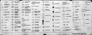
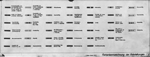
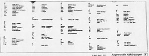
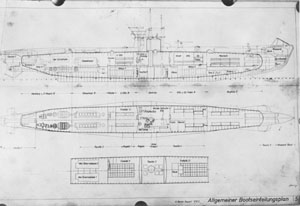
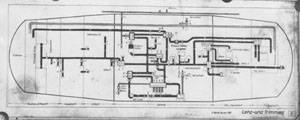
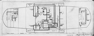
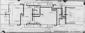
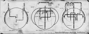
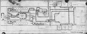
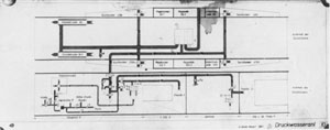
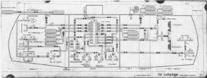
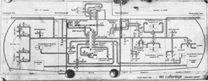
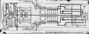
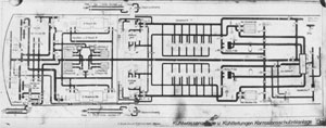
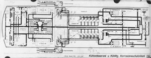
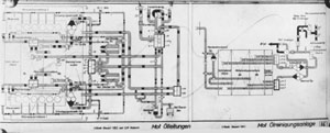
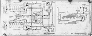
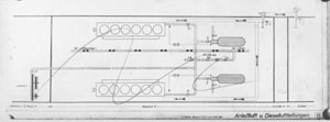
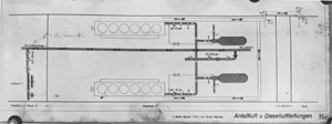
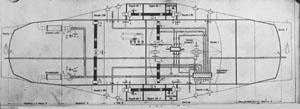
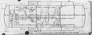
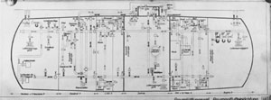
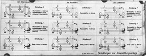
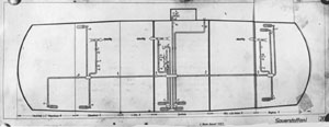
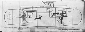
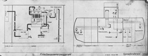
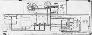
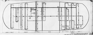
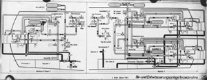
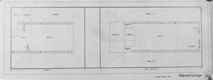
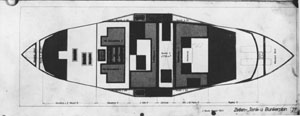
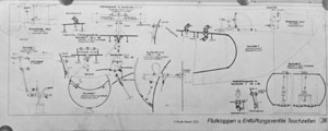
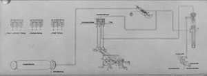
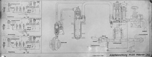
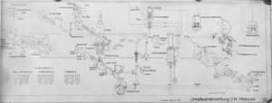
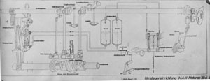
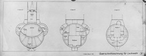
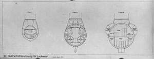
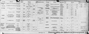
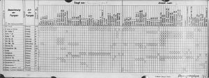
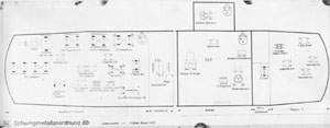
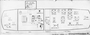
        Ensign Anderson also photographed certain system diagrams of the submarine which were available on board at the time of the inspection.


        The Taylor Model Basin has translated the German legends and titles on these diagrams and has redrawn and reproduced them for ready reference use, complete with both German originals and English translations.


        The translation was done by F. Ravenm Senior Translator, of the TMB Staff, with the aid and advice of Captain H.E. Saunders, USN, who also edited the work for technical correctness.


Click on the thumbnails below to view a full sized diagram and key

The following format will be used for each plate of the sketchbook

First: David Taylor reproduction with English translations (based on Ensign Anderson's photograph of the German original found on board U-570)
Second: Translated Key with German text in capital letters followed by the English translation
Third German Key
Fourth German Plate


  Title Page - Sketchbook for the Technical Personnel, Volume M
     
  Regulations
     
  Table of Contents
     
  Plate 1: Form of hand wheels, hand cranks and valve identifications
     
  Plate 2:  Symbols used
     
  Plate 3: Color identification of pipe lines, conduits, and tubes
     
  Plate 4:  Abbreviations used
     
  Plate 5:  General arrangement of vessel
     
  Plate 6:  Trimming, compensating and drainage system
     
  Plate 7:  Regulating and compensating system
     
  Plate 8:  Fuel oil venting, sounding and test piping (longitudinal section)
     
  Plate 8A:  Fuel oil venting, sounding and test piping (cross-sections)
     
  Plate 9:  Fuel oil onboarding, transfer, and delivery system
     
  Plate 10:  Fuel oil compensating system (circulating water under pressure)
     
  Plate 11:  High pressure air system
     
  Plate 12:  Low pressure or service air system
     
  Plate 13: Cooling-water system and anti-corrosion oil-circulating system; for ships with Krupp engines
     
  Plate 13A:  Cooling-water system and anti-corrosion oil-circulating system; for ships with MAN engines
     
  Plate 13B:  Cooling-water system and anti-corrosion oil-circulating system; for Submarines U93-U97
     
  Plate 14:  (Left) Engine lubricating oil system, (Right) lubricating oil storage, sump and purifying system, for Krupp engines
     
  Plate 14A:  (Left) Engine lubricating oil system, (Right) lubricating oil storage, sump and purifying system, for MAN engines
     
  Plate 15:  Engine starting air and induction air (for Krupp engines)
     
  Plate 15A:  Engine starting air and induction air (for MAN engines)
     
  Plate 16:  Flooding, venting, low pressure exhaust gas and emergency blowing systems
     
  Plate 17:  Blowing and emergency blowing systems for ballast, regulating and diving (negative buoyancy) tanks
     
  Plate 18: Compartment ventilating and supply systems (emergency ventilating)
     
  Plate 19:  Ventilating diagrams for surface, submerged, running and charging conditions
     
  Plate 20:  Oxygen system
     
  Plate 21:  Fresh water, wash water, waste and sanitary systems
     
  Plate 22:  (Left)  Evaporating and distilling system;  (Right)  voice tube system
     
  Plate 23  Hydraulic system for operating periscopes
     
  Plate 24:  Steam heating system
     
  Plate 25:  Torpedo tube firing, venting, flooding and drainage systems
     
  Plate 26:  Lime-water (acid neutralizing) system (for battery compartments)
     
  Plate 27:  Arrangement of compartments and tanks, and tank capacities
     
  Plate 28:  Flooding and venting system for ballast and buoyancy tanks
     
  Plate 29:  Air starting gear for Krupp engines
     
  Plate 29A:  Air starting gear for MAN engines
     
  Plate 30:  Reversing gear for Krupp engines
     
  Plate 30A:  Reversing gear for MAN engines
     
  Plate 31:  Cross-sectional arrangements for leakage control
   
     
  Plate 32:  Specifications for hose and connections for piping systems
     
  Plate 33:  Pumping plan
     
  Plate 34:  Vibration and noise absorbing mountings, port and starboard