This report was transcribed from the original located in the U.K. Archives at Kew. It was provided to the U-boat Archive by U.K. researcher Roger Griffiths. |
COPY No. |
|||
|
|||
C.B. 4318 |
|||
R |
|||
REPORT |
|||
ON |
|||
"U-570" |
|||
(H.M.S. "GRAPH") |
|||
1943 |
|||
Attention is drawn to the penalties attaching to any infraction of the Official Secrets Acts. |
||
C.B. 4318 |
||
R |
||
REPORT |
||
ON |
||
"U-570" |
||
(H.M.S. "GRAPH") |
||
1943 |
||
| INTELLIGENCE DIVISION | ||
| NAVAL STAFF, | ||
ADMIRALTY. |
||
January, 1943. |
||
| (M.O.6073/42.) | ||
2 |
||||||||||||||||||||||||||||||||||||||||||||||||||||||||||||||||||||||||||||||||||||||||||||||||||||||||||||||||||||||||||||||||||||||||||||||||||||||||||||||||||||||||||||||||||||||||||||||||||||||||||||||||||||||||||||||||||||||||||||||||||||||||||||||||||||||||||||||||||||||||||||||||||||||||||||||||||||||||||||||||||||||||||||
CONTENTS |
||||||||||||||||||||||||||||||||||||||||||||||||||||||||||||||||||||||||||||||||||||||||||||||||||||||||||||||||||||||||||||||||||||||||||||||||||||||||||||||||||||||||||||||||||||||||||||||||||||||||||||||||||||||||||||||||||||||||||||||||||||||||||||||||||||||||||||||||||||||||||||||||||||||||||||||||||||||||||||||||||||||||||||
|
||||||||||||||||||||||||||||||||||||||||||||||||||||||||||||||||||||||||||||||||||||||||||||||||||||||||||||||||||||||||||||||||||||||||||||||||||||||||||||||||||||||||||||||||||||||||||||||||||||||||||||||||||||||||||||||||||||||||||||||||||||||||||||||||||||||||||||||||||||||||||||||||||||||||||||||||||||||||||||||||||||||||||||
PLATES |
||||||||||||||||||||||||||||||||||||||||||||||||||||||||||||||||||||||||||||||||||||||||||||||||||||||||||||||||||||||||||||||||||||||||||||||||||||||||||||||||||||||||||||||||||||||||||||||||||||||||||||||||||||||||||||||||||||||||||||||||||||||||||||||||||||||||||||||||||||||||||||||||||||||||||||||||||||||||||||||||||||||||||||
|
||||||||||||||||||||||||||||||||||||||||||||||||||||||||||||||||||||||||||||||||||||||||||||||||||||||||||||||||||||||||||||||||||||||||||||||||||||||||||||||||||||||||||||||||||||||||||||||||||||||||||||||||||||||||||||||||||||||||||||||||||||||||||||||||||||||||||||||||||||||||||||||||||||||||||||||||||||||||||||||||||||||||||||
3 |
||
CHAPTER I |
||
EARLY HISTORY AND CAPTURE |
||
"Graph," ex "U 570," is a 500-ton U-Boat, Type VIIC, and was built at the Blohm & Voss Yards, Hamburg. Commissioned on 15th May, 1941, with a crew consisting of 4 officers, 3 chief petty officers, 11 petty officers and 25 men, she carried out trials, mainly from Kiel and Horton, on Oslo Fjord, until about 23rd July, when, during a crash dive from a suspected British aircraft, she struck a reef and damaged her bows. At the end of July, 1941, she was docked at Ytrre Havn for repairs and after further trials she was ready for her first patrol on 22nd August, 1941. |
||
2. On 24th August "U 570" left the fjord and proceeded mainly on the surface to an area south of Iceland. She dived twice for aircraft but breakdowns of machinery caused more trouble than did the attentions of her enemies. This unsatisfactory state of affairs was quickly reversed, however, at about 1050 on 27th August. "U 570" at this time was diving deep to get some respite from the heavy seas which had already caused much seasickness amongst her crew. Possibly in order to take a sight, her captain decided to surface and, neglecting the elementary precaution of ensuring it was safe to do so, came up almost immediately underneath a Hudson aircraft "S" belonging to 269 Squadron, piloted by Squadron Leader Thompson. "U 570" perceived her danger too late and, as she was diving, a stick of four 250 lb. depth-charges exploded close alongside her. The lights were put out and some gauge glasses fractured, and it was doubtless the sound of water pouring through these, added to the confusion caused by the blackness (the auxiliary lighting system having failed) and the panic of an inexperienced crew that caused the captain to order the boat to be brought to the surface and surrendered. |
||
3. As soon as the submarine surfaced the aircraft attacked with guns until about a dozen of the crew, who had emerged from the boat on to the bridge, waved a white flag. |
||
4. In a short while the entire crew had gathered on the bridge. The sea was too rough to sink their ship and take to a raft and they do not appear to have considered it politic to attempt to drive off the aircraft with their A.A. gun. Huddled in their miserable position the crew remained throughout the day. At 1345 the Hudson was relieved by a Catalina. As the day drew on a few members of the crew regained some measure of composure. The confidential books and papers and cypher machine were thrown overboard and the A.E.G. gear smashed. A wireless message was passed to the Vice-Admiral, U-Boats, stating their position. |
||
5. Later, some unskilled and unsuccessful attempts were made to repair the damage, but, at the approach of the trawler "Northern Chief" at 2250, all efforts were abandoned. H.M.S. "Burwell" arrived at 0550 and immediately received this signal from "U 570": "Will you take off our crew?" to which "Burwell" replied, "Blow main ballast tanks and send half your crew below." No reply was received and a further signal was made: "Do not attempt to throw any papers overboard and do not attempt to scuttle," which elicited the reply," What does scuttle mean?" Several unsuccessful attempts were then made by "Burwell" and "Windermere" to take "U 570" in tow. At 1030, after "U 570" had signalled many times, "Will you take off our crew, we are sinking," "Burwell" replied, "Blow all fuel overboard." |
||
6. No action was taken, nor did any of the crew go below. The submarine appeared to be settling deeper in the water, so the Commanding Officer, H.M.S. "Burwell," ordered a burst of machine-gun fire to be fired over the bridge. The gunner's aim was spoilt by the heavy seas and five of "U 570's" crew were wounded. Others rushed below and the main ballast and fuel tanks were blown, and the submarine for the first time since its capture appeared to be in a reasonable condition of buoyancy. |
||
7. At 1350, after more unsuccessful attempts to tow "U 570," she asked for her wounded to be removed. Two officers and ratings from the trawler "Kingston Agate" went alongside in a Carley raft, and were almost overwhelmed in the concerted rush made by the officers, who had to be forcibly persuaded back on board in order that the wounded might be removed first. |
||
8. It was not until 2100 hrs. that "U 570" was finally got in tow. Unfortunately, in the intervening period some of the trawlers had removed the entire crew which resulted in a loss of control over the submarine which nearly caused her total loss. As it was, since the submarine appeared to be slowly losing buoyancy, she had to be taken to the nearest land and was eventually beached at Thorlakshafn, about 24 hours later. It had been intended to beach her bows on and hold her in that position with appropriately located anchors. In fact, the submarine beached herself broadside on before this operation could be carried out. |
||
9. On 30th August, Lieutenant G.R. Colvin, Wt. Engineer Giordan, an E.R.A. and P.O. L.T.O. arrived by air at Reykjavik and proceeded the following day to Thorlakshafn, boarding the submarine through breaking surf at 1300. |
||
10. "U 570" was then lying broadside on to the surf and listing heavily to starboard (i.e. in shore). She was on a gently shelving beach of soft sand, completely open to the south-east, and had been driven well up the beach by a moderate swell. The interior of the submarine was unlit and in a chaotic state. Leaks of oil and water from broken gauge glasses of internal tanks had combined with vast quantities of provisions, flour, dried peas and beans, soft fruit, clothes and bedding, and the remains of scores of loaves of black bread to form a revolting morass that in places was knee deep. It was subsequently discovered that the crew's W.C. had been converted into a food locker and overturned buckets of excrement added to the general noisome conditions. |
||
(C50426) B2 |
||
4 |
||
11. The following damage had been done by the crew: |
||
(i) The engine room was flooded to the deck plates due to the removal of a strainer cover. This had been replaced by the crew themselves but not rendered completely watertight. |
||
(ii) A.E.G. gear completely smashed. |
||
(iii) W/T set damaged. |
||
(iv) Attack instrument dials smashed. |
||
(v) Anschutz compass dropped. |
||
(vi) Control room and conning tower deep diving gauges defaced. |
||
(vii) Forward periscope lowered into its well and the well filled with oil and water. |
||
12. The following damage was caused by depth charges: |
||
(i) 3-in. split in pressure hull on port side. |
||
(ii) 90 per cent. battery containers cracked. |
||
(iii) Bulkhead between both battery tanks and internal O.F. tanks slightly buckled. |
||
(iv) One of two pairs of 500-amp. fuse holders broken. This caused the loss of all lighting and power to auxiliaries. |
||
(v) Battery supply switches to the main motor switchboards jumped off but were undamaged. |
||
(vi) Several gauge glasses, lights, porcelain fuses and a few minor bracket welds broken. |
||
13. Between p.m. on Sunday, 31st August, and 0500, Friday, 5th September, the submarine was made seaworthy. This involved the restoration of lighting, the tracing of all air and water services throughout the boat, finding and shutting vents, Kingstons, bulkhead and tankside valves, blowing main ballast tanks with the little air remaining, pumping out the bilges with a small semi-rotary pump and clearing the ship of some of the fifth. |
||
14. At 0500 on Friday, 5th September, "U 570" was hauled off the beach by the salvage tug "Salvoina" and floated with a 3° list to starboard and slightly bow down. Main ballast was further blown by a portable L.P. air compressor brought alongside by a corvette, and at 1300 the passage to Hvalfjord commenced. |
||
15. The air in the submarine had now become almost unbreathable and Lieutenant Colvin and his party remained on the bridge in the extreme cold throughout the passage. The weather was favorable and the submarine arrived alongside H.M.S. "Hecla" at 0930 on Saturday, 6th September. |
||
16. The work of preparing the submarine for passage under her own power to Barrow-in-Furness now commenced, and by 25th September she was in all respects ready for Sea, her crew having joined four days earlier and sea trials having been carried out on the previous two days. |
||
17. At 1600 on 29th September, "U 570" left Iceland, escorted by H.M.S. "Saladin," arriving at Barrow at 0900 on 3rd October, having made good 13 knots for the majority of the passage. |
||
SHORT GENERAL DESCRIPTION |
||
| "Graph," although nominally a 500-ton U-Boat, has a surface displacement of 784 tons, including approximately 42 tons of oil fuel in Nos. 2 and 4 external main ballast tanks, and a submerged displacement of 883 tons. Overall length is 220 ft. with a pressure hull diameter of 15.6 in. Her maximum surface speed is 18.8 knots. | ||
| 2. One hundred and nine tons of fuel are carried, about 55 per cent. inside the pressure hull and the remainder in external tanks which can also function as main ballast tanks. This gives the submarine a surface endurance of about 7,500 miles at 10 knots on both engines. | ||
| 3. Submerged speed is 8 knots and endurance is slightly less than for our own submarines. | ||
| 4. The pressure hull thickness is 0.88 in. amidships, decreasing to 0.63 towards the end. End dished bulkheads are 1.378 in. thick. Except for the cover plates over the engine room and the dished bulkheads at each end of the internal main ballast tanks where riveting is used, the pressure hull which is of circular section throughout, is welded. The greater part of the welding has the appearance of having been done in the shops. | ||
| 5. One large main ballast tank is within the pressure hull - an undesirable feature. Other main ballast is in external saddle tanks and at the ends of the submarine. When carrying full stowage of fuel (i.e., with fuel in the main ballast tanks) the reserve buoyancy is only 99 tons, which is small compared with British practice. | ||
| 6. A good bow form is made possible by having only four internal bow tubes. The forward hydroplanes are of the drowned type and not arranged to house; both forward and aft hydroplanes protrude further than in our submarines. Control of the submarine dived is good. Projecting hydroplanes, together with the light jumping wire, flimsy hydroplane guards and flimsy spur to protect the rudder and screws when bottoming indicates that passage through anti-submarine nets is not regarded as important. | ||
| 7. Vents bow caps and torpedo transport are all hand worked. Many fittings standard in British submarines, such as drop keel, gun access trunk, L/P blowers, wireless mast, torpedo derrick, traversing rails and hunting gears are omitted. Without these omissions hopeless congestion would arise. As it it, congestion is serious in the forward and after ends, and living quarters are very cramped. | ||
5 |
||
8. The fixed eyepiece periscope, operated from the conning tower, enables the silhouette to be kept very low. This, together with a low reserve buoyancy, when carrying oil fuel in main ballast tanks, makes the bridge extremely wet in short seas. Experience has proved, however, that though she rides comfortably in a heavy swell, speed has to be considerably reduced. |
||
9. Kingstons and vents are large compared with ours. The internal main ballast tank is fitted with two large hand-worked vents, two intermediate vents and six large, square kingstons. The latter open outwards and are protected by a plate protruding from the pressure hull. |
||
10. Twin rudders are fitted aft. This is necessitated by the central (internal) torpedo tube aft. This double rudder does not give a better turning radius than in "S" class submarines. |
||
11. The battery ventilation is by means of the "separate cell ventilation system." |
||
12. The engine room hatch is fitted as an escape hatch. |
||
13. A small refrigerator, combined with little stowage for food and a small galley, reduce living conditions below the British standard. |
||
Engineering |
||
14. The engines are as large as can possibly be fitted in the available space with a fairly low shaft centre line. The four-stroke engines are of 15.75 in. bore and 18.1 in. stroke, 6 cylinder, reversible, with engine-driven positive displacement superchargers. The latter are driven through double cone clutches. |
||
15. Double cone engine and tail clutches are fitted. |
||
16. Auxiliaries are generally electrically or air operated. |
||
Electrical |
||
17. The general principles of the electrical installation are similar to those adopted in our modern submarines. A main battery in two sections (62 cells in both sections) provides the power and tandem main motors on each shaft provide for submerged drive. |
||
18. Both batteries and motors can be grouped in series or parallel. The control gear for varying these groups and for starting and reversing the main motors is semi-automatic and is so designated that comparatively little training of the operators is required. |
||
19. The auxiliary electric circuits are fed by a double tree system from auxiliary switchboards situated at the main switchboard and in the control room. Such a system is used in small British surface ships, but not in submarines, where a ring main is preferred. |
||
20. The submarine did not appear to have been "wiped" or "flashed" but may have been "depermed." |
||
Armament |
||
21. Torpedo armament comprises four bow and one stern torpedo tube. |
||
22. Seven re-loads are carried internally and two externally, making a total of 14 torpedoes. |
||
| 23. Torpedo tubes and fittings are of excellent finish and the gear connected with them is readily accessible. Gyro angling gear is more complicated than ours but permits application of very accurate angling up to the last moment of the attack. | ||
| 24. Firing gear is similar to ours, but the torpedo is ejected from the tube by a ram which gives certain splashless discharge. | ||
| 25. The bow cap is very similar to our design. Embarkation and loading of torpedoes is by hand with an overhead rail. | ||
| 26. "Graph" had no mines aboard but it would seem she could carry up to 36 mines. | ||
| Gunnery | ||
| 27. "Graph" mounts: | ||
| (a) One 88 mm. gun on deck before the conning tower, giving maximum range of 13,000 yards. Outfit of ammunition about 150 rounds. | ||
| (b) One 20 mm. Solothurn type A.A/L.A. gun on the after end of the bridge. Outfit of ammunition for this gun is not known. | ||
| (c) An unknown number of 7.92 mm. machine guns. None was found on board, though it is known they were carried. | ||
| Acoustic Apparatus | ||
| 28. The outstanding feature is the number and complication of the acoustic equipment. There are over 70 hydrophones and oscillator units fitted in the hull. | ||
| W/T Equipment | ||
| 29. This is similar but of lower power than in British submarines. | ||
| Conclusion | ||
On the whole, it may be said that "Graph" was built - and well built - for the sole purpose of offensive action in war. In addition, the centralization of most controls and the number of automatic and semi-automatic fittings make it obvious that she has been designed to be run by an inexperienced crew with the minimum of experienced ratings. She was not captured through any serious defect of material, but as a result of being poorly manned. |
||
| (C504426) B3 | ||
6 |
||
CHAPTER I I |
||
ELECTRICS |
||
Main Motor Switchboards |
||
1. The starting arrangements consist of inserting a resistance in series with the tandem armatures; this resistance is short-circuited by means of a contactor and current relay as soon as the current has fallen to a predetermined value. |
||
2. The field switch on each motor is automatically closed on the closing of the main motor circuit breakers. |
||
3. The automatic features make it easier for an unskilled crew to operate the board, but definitely increases maintenance and the possibility of faults. |
||
4. All automatic switches can be operated by hand if necessary. |
||
5. The switchboards are of the enclosed type and very little of the operation can be seen without removing the covers. |
||
6. The boards are open for inspection at the back and connections are quite easy to get at; the exception is the main motor field regulators, which are enclosed. |
||
7. The non-automatic switches are as follows: Ahead astern switch, motor series parallel switch, battery series parallel switch. These switches are fitted with flipper blades and the motor circuit can be broken or made on all of them. |
||
8. Special attention has been given to sound insulate the above switches and their flipper blade with a resilient rubber. |
||
9. The field regulator is wound on porcelain formers and, while the whole gear is very robust, it is not certain how it would stand up to severe shock. |
||
10. All connections are of copper and of massive construction. |
||
11. The arc shields on the main motor contactor consist of two-ply syndanyo with an additional layer of bakelite on the outside. The layers are compressed and the material is very strong. |
||
Main Motors |
||
The main electric drive consists of two tandem armature sets of 465 kw. each. The armatures can be grouped in parallel or series and the batteries in parallel or series to give the desired speed range. |
||
The tandem fields can be grouped in parallel or series as required. |
||
The general design and construction is more or less in accordance with our own motors; the following points are, however, of interest: |
||
(i) The main yoke can be rotated by a worm on the outside of the main motor yoke casting (i.e., the external yoke is a fixture). |
||
| (ii) The yokes are of steel and the end brackets and cover plates of aluminium alloy. Very little attempt appears to have been made to shockproof the machines. | ||
| (iii) Each tandem set has four holding-down lugs, each lug is held down by two bolts and located by one dowel. | ||
| (iv) The aft port main motor can be used to give six volts for sick-cell charging, by alteration of the field system. | ||
| (v) Each armature can be used separately in the event of failure of the other. | ||
| (vi) The main motors are very silent in operation but the chain-driven speed indicator is noisy. | ||
| (vii) Main Motor Cooling System. Fan blows air into centre of machine and exhausts into trunking at each end, the trunking leads into water coolers between tandem sets, the air is then exhausted into atmosphere. | ||
| The fan motors are on resilient mountings and are connected to run only when the main motors are running. | ||
| Auxiliary Motors | ||
| 1. The motors take their supply from the 110-170-volt V.P. boards either in the main motor room or the control room. In the event of failure of the supply from one board, the supply can be maintained to the motors from the other board by means of a change-over switch. | ||
| 2. In general the motors are of very solid construction and no lack of material or labour is evident in their make-up. | ||
| 3. The field and armature system are in accordance with our own design with the exception of the series starting coils, which are superimposed on the field coil system. | ||
| 4. Yokes are made of steel, and in the smaller machines the end brackets are made of cast aluminium alloy. The air compressor, ballast and trim pumps have cast iron or malleable iron end brackets, all fan cowls and cover plates are made of alloy. | ||
| 5. The air compressor motor and forward hydroplane and steering motors are horizontal machines, all the other large machines, e.g., ballast, trim and telemotors, are vertical machines. In no case are the yokes or end brackets split. | ||
7 |
||
6. All auxiliary motors are fitted with ball bearings. In some cases the method of lubrication appears to be very inefficient as grease can only be inserted by opening up the speed indicator plug. In other cases Stauffer boxes are used. |
||
7. The machines appear to withstand heavy starting currents without sparking and the commutators, with the exception of the two ventilating fans, are in very good condition. |
||
8. There is no definite auxiliary machinery space and the ballast, telepumps and cooling plant are in the aft end of the control room. The capstan is operated by compressed air and there is no D.H. plant or L.P. blower. |
||
9. The majority of auxiliary machines are mounted on resilient mountings; the main exceptions being the air compressor, ballast and trim pumps. The trim pumps can be dispensed with while dived by using L.P. air, but this is not possible with the ballast pump. |
||
10. The steering and hydroplanes are all electric drive, the steering motor is controlled by push buttons from the control room, conning tower, and bridge, and hydroplanes from control room only. Steering and hydroplanes can be operated by hand through shafting in the event of failure of the motor or supply. |
||
11. There is no field regulation for the ballast or trim pumps and the output of the pumps is controlled by opening and shutting the valves. |
||
12. There are two condensers fitted between the positive and negative brushes of nearly all motors. The centre point is earthed. It is believed that these are fitted to prevent wireless interference. There is also the possibility that they may prevent excessive sparking in starting up. |
||
Auxiliary Motor Starters and Controllers |
||
1. From a casual look it would appear that the starters are very much smaller than the corresponding British type of the same rating; on closer inspection, however, it is found that in addition to the starter there is a large double pole rotary switch and a 6-in. ammeter. This arrangement enables the equipment to be better spaced out over the available space on the hull, but entails a considerable amount of additional wiring. |
||
2. Three or four motors are wired back to a common change-over switch, so that the supply can be obtained from either V.P. board. |
||
3. All starters and switches are watertight and have packed glans. In order to make a continuous connection between the cable braid and the starters or switch case, a piece of wire is twisted round the braid inside the gland and clamped by a set screw on the gland. |
||
4. Small flexible leads are used extensively throughout the vessel for earthing purposes. |
||
5. In general, all starters, switches and ammeters are fixed on resilient rubber mountings. It is considered that these mountings are primarily intended as shock absorbers and secondly as sound insulating mountings. |
||
6. The motors in general are started by inserting an auxiliary series field coil in the armature circuit, as soon as the motor is under way, this coil is shorted out and the motor connected directly across the line. The two-step start is quite noticeable to the ear when the machine is started. |
||
7. Small machines are started by connecting straight to the line through a double pole rotary switch. |
||
8. All Controller and Starter covers are removable, hinges are not used. |
||
Auxiliary Switchboards |
||
1. There are two auxiliary switchboards; one in the main motor room and one in the control room and they can be connected either to the forward or after battery or both; the forward main supply is obtained from the forward battery through the battery circuit breaker (3,000 amp.); the alternative supply to this board is obtained from after battery through 430 amp. 500-volt fuses and vice versa. |
||
2. Each board is divided into two, one part supplies the V.P. machinery and the ammeter on the board reads up to 600 amps. The other part of the board supplies the C.P. circuits and the voltage is maintained at 110 volts + 4 volts by means of a Brown Boverie automatic voltage regulator and a resistance bank. The voltage regulator can also be hand operated. |
||
| 3. Siemens cartridge fuses are used throughout the vessel for power, heating and lighting, the smaller fuse holders for heating and lighting are made of porcelain, the larger fuse holders are made of black moulded compound, the only exceptions to this type of fuse are the 480 amp. battery fuses on the battery circuit breakers. | ||
| 4. There is a battery ampere hour meter for each battery in the main motor room. | ||
| Lighting and Heating | ||
| 1. The lighting supply comes from the C.P. board either in the control room or in the main motor room and is maintained at 110 volts + 4 volts by means of a Brown Boverie automatic regulator and resistance bank; it will be noted that this regulator cannot boost the output voltage to 110 volts if the input voltage has fallen below 110 volts. | ||
| 2. The heating supply is taken from the V.P. board either in the control room or main motor room and the voltage varies between 110 and 170 volts according to the state of the batteries. | ||
| (C50426) B4 | ||
8 |
||||||||
3. The radiators are wound to suit the variable voltage. |
||||||||
4. The vessel is well lit and provided with well glass fittings; the glass may be toughened glass, no well glass lights were broken by the explosion of the bombs during action. |
||||||||
5. All wiring, fittings, fuze boxes, distribution boxes, for heating and lighting circuits are watertight. |
||||||||
6. There are several portable lamps and radiators with flexible leads which plug into watertight sockets. |
||||||||
7. There is an emergency lighting supply by battery in each compartment in case the main lighting supply should fail. This battery supply is connected by a relay with the lighting circuit so that in the event of failure the battery is automatically connected to a small wattage lamp. It is believed that the batteries were dry cells but as they had been removed from the boxes it is not possible to be certain. |
||||||||
8. The fuse and distribution boxes are of the quick close and open type and are made of aluminium alloy, the quick close handle is made of steel, the boxes are very neat in design and are intended for quick operation. |
||||||||
9. Cartridge fuses with porcelain holders are used throughout, and several of the holders were broken. |
||||||||
10. All 110-volt lamps are of the Edison screw type. |
||||||||
Torpedo Charging and Heating |
||||||||
1. There are two motor generators in the aft compartment with inputs of 110-150 volts at 5 amps. These appear to act as boosters to the 110-volt supply for torpedo charging and this output is + 30/-40/-10 volts. |
||||||||
2. There is a flexible lead, one end of which can be plugged into the charging panel, the other end of the lead plugs into the torpedo. |
||||||||
3. No means have been found of charging the torpedoes in the torpedo tubes and it is thought that they may have to be withdrawn to be charged. |
||||||||
4. The supply to the heating circuit for the torpedoes comes through an automatic switch from the V.P. circuit. A changeover switch makes it possible to take the supply from either V.P. panel. |
||||||||
5. The torpedoes can be heated while in the tubes by means of a flexible cable from the torpedo heating plug. |
||||||||
6. The plug which goes into the torpedo goes through a hole in the forward top end of the torpedo tube and then into the side of the torpedo. This hole in the torpedo tube can be made watertight by means of a screw plug on a rubber seating. |
||||||||
7. There is no interlock arrangement to prevent the torpedoes being fired while the plug is in position. |
||||||||
Cables |
||||||||
1. Flexible cables, steel braided, are used throughout the vessel and are rubber insulated. |
||||||||
| 2. Many small cables are used in parallel for the main supply leads (there is no ring main as in British practice). The higher rating of the smaller cables and their flexibility may be an advantage. | ||||||||
| 3. The cables are bunched at each bulkhead and go through a watertight box (one starboard and one port), these boxes are filled with sealing compound and it would be extremely difficult to replace a cable if it should become faulty. There are as many as forty-eight cables in one bunch. | ||||||||
| Telephones and Telegraphs | ||||||||
| 1. Sound power telephones are fitted throughout the vessel; each instrument has a six-way selector switch, a magneto ringer and bell, all instruments are fitted with rubber mountings. The speech is very clear but not very loud and some difficulty is experienced in hearing in engine room when main engines are running. | ||||||||
| 2. A broadcast system is fitted in the vessel; all instruments are mounted on rubber. | ||||||||
| 3. The following equipment is operated by the 110 volts C.P. supply: | ||||||||
|
||||||||
| 4. There is no low power system in the ship. | ||||||||
9 |
||||||||||||||||||||||||||||||||||||||||||||||||||||||||||||||||||||||||||||||||||||||||||||||||||||||||||||||||||||||||||||
LIST OF MACHINES |
||||||||||||||||||||||||||||||||||||||||||||||||||||||||||||||||||||||||||||||||||||||||||||||||||||||||||||||||||||||||||||
Brown Boverie et Cie. Akleingesellschaft, Mannheim. |
||||||||||||||||||||||||||||||||||||||||||||||||||||||||||||||||||||||||||||||||||||||||||||||||||||||||||||||||||||||||||||
|
||||||||||||||||||||||||||||||||||||||||||||||||||||||||||||||||||||||||||||||||||||||||||||||||||||||||||||||||||||||||||||
10 |
||||||||||||||||||||||||||||||||||||||||||||||||||||||||||||||||||||||||||||||||||||||||||||||||||||||||||||||||||||||||||||||||||||||||||
|
||||||||||||||||||||||||||||||||||||||||||||||||||||||||||||||||||||||||||||||||||||||||||||||||||||||||||||||||||||||||||||||||||||||||||
11 |
||||||||||||||||||||||||||||||||||||||||||||||||||||||||||||||||||||||||||||||||||||||||||||||||||||||||||||||||||||||||||||||||||||
|
||||||||||||||||||||||||||||||||||||||||||||||||||||||||||||||||||||||||||||||||||||||||||||||||||||||||||||||||||||||||||||||||||||
12 |
||||||||||||||||||||||||||||||||
|
||||||||||||||||||||||||||||||||
Resilient Mountings |
||||||||||||||||||||||||||||||||
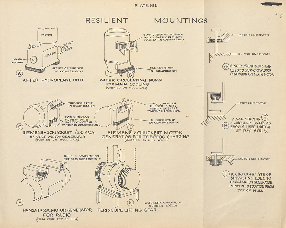
1. It will be observed that almost every auxiliary machine is resiliently mounted. In addition, practically every instrument, indicator, contactor or switch is mounted on small rubber bounded units. The consistency with which this has been carried out whether the apparatus was small or large, is most impressive. As no question of sound insulation can arise in such cases the natural and doubtless correct explanation is that all the resilient mounting of instruments, switch gear and contactors, is to prevent damage by shock. |
||||||||||||||||||||||||||||||||
2. The rubber mounting of auxiliary machinery may be to prevent damage by shock, or alternatively it may be to prevent detection. A further strong possibility is that of preventing local interference with the submarine's own acoustic devices which are extensive. |
||||||||||||||||||||||||||||||||
3. If the reason for providing resilient mounting is to prevent shock damage to machines, then it is difficult to understand why such mountings have been omitted from four machines which are quite as vital to the operation of the ship as many other which have been most carefully insulated from their supports. |
||||||||||||||||||||||||||||||||
4. The reason for omitting to rubber-mount the two h.p. air compressors and the ballast and trimming pumps can, however, be explained without difficulty if the insulation is to prevent noise reaching the water. The h.p. air compressors would only be used on the surface, and alternative methods of trimming by means of compressed air can be used to make operation of the trimming pump unnecessary if quiet conditions are imperative. In addition, the ballast and trimming pumps are auxiliaries which would only be used for short periods, and would not be likely to provide a continuous source of interference with the submarine's own listening devices. |
||||||||||||||||||||||||||||||||
5. It is, therefore, concluded that the primary reasons for sound insulating the auxiliary machinery are to prevent detection and also to prevent interference with acoustic reception, while the resilient mounting of instruments, etc., is to prevent shock damage. |
||||||||||||||||||||||||||||||||
6. A detailed inspection of the methods adopted in providing rubber insulation for auxiliary machinery indicates that a great deal of ingenuity has been used. The three important and outstanding differences between the methods employed when compared with British methods are as follows: |
||||||||||||||||||||||||||||||||
(i) The natural frequency of the machines on their mountings is comparatively high, but very soft rubber is used with a very light loading. |
||||||||||||||||||||||||||||||||
(ii) No attempt is made to provide sound insulation in pipe systems, or in any other mechanical control connection which effectively short circuit the rubber insulation. |
||||||||||||||||||||||||||||||||
(iii) Machines are in no case mounted directly on to the tank tops on large deck surfaces, but are usually carried directly on the hull frames or on light angle frames between deck and hull. |
||||||||||||||||||||||||||||||||
7. With regard to (i), the insulation of very low frequencies under this method may be expected to be less effective, but for the higher frequencies results may well be improved, and the light loading makes compete reliance on rubber to metal bending more satisfactory. |
||||||||||||||||||||||||||||||||
8. Insulation of pressure pipes and mechanical control systems (ii) may possibly have been found to make insufficient difference to warrant the additional complications. |
||||||||||||||||||||||||||||||||
9. The methods of mounting machines vary considerably and the illustrations in Fig. 1 attached shows a selection of those employed. In addition to the machines shown in Fig 1, similar methods are used for other machines as follows: |
||||||||||||||||||||||||||||||||
| ||||||||||||||||||||||||||||||||
13 |
||
10. While the motor generators shown above were, in general, mounted in a similar manner to that shown in Fig. E, and hung from the top of the hull, in some cases the simple compression rubber strips were replaced by smaller circular compression units, and in one case by a type shown at Fig. H. |
||
11. The 6 K.V.A. Hansa motor generator was hung on four circular shear units as shown at Fig. I. |
||
12. The mounting of the periscope lifting gear is rather novel (Fig. F), but it is not known if the rubber extends completely through the tubes shown, or is only a ring of rubber inserted in each end. |
||
GERMAN SUBMARINE CELLS - TYPE 33 MAL. 800W |
||
Examination of Cells |
||
One of the five cells from the main battery of "Graph" was dismantled for examination. The main dimensions of the cell are given in Table 1, together with those of representative British types. |
||
2. The cells are somewhat larger than the standard British cells and somewhat smaller than the large cells used in "Thames" class submarines. The outstanding feature in the design is that a large number of thin plates is used. The negative plates are 3 mm. (3.7 mm. pasted) and the positive plates are 3.5 mm. (4 mm. pasted) thick compared with 5 mm. and 6 mm. respectively for the plates of a "Tudor" cell and 4.75 mm. and 6.4 mm. respectively for the plates of a "D.P." cell. |
||
3. A multiple type of separator, 2.3 mm. thick overall, is used consisting of a corrugated perforated ebonite sheet next to the positive and a plain wooden separator 0.6 mm. thick next to the negative. |
||
Capacity Tests |
||
4. Four of the cells were given a refreshing charge at a low rate and were then subjected to charge and discharge tests in order to determine their capacity at different discharge rates. The cells, during these tests, were immersed in a water bath maintained at 80° F., (the temperature laid down in the Admiralty Specification for Submarine Main Batteries). |
||
5. During the capacity tests, the cells were charged in accordance with the instructions contained in the General Instructions Booklet of Akkumulatoren Fabrik A.G.; that is, the cells were charged at 1650A until the potential difference per cell reached 2.40 volts, the charging rate was then reduced gradually to maintain the voltage constant at this figure until the current fell to 415A at which rate the charge was continued until the cell voltage and the electrolyte density remained constant for one hour. |
||
6. Tests were made with discharge currents corresponding to the nominal 8-hour, 5-hour and 1-1/2 hour rates as given in the General Instructions Booklet and these tests were later repeated in random order. |
||
7. After a full charge, the cells were kept on open-circuit for seven days with the temperature of the bath raised to 100° F., and the capacity at the 8-hour rate was then measured at a temperature of 80° F. The potential of the negative plate as given by a cadmium electrode was 0.34 volt as compared with 0.32 volt at the end of a normal discharge showing that the loss on open circuit (amounting to about 3.5 per cent.) was mainly due to the negative plate. |
||
8. The voltages, given in the General Instruction Booklet for these cells, at which the discharge is to be considered complete, differ from those customarily used for British submarine cells. At both the 8-hour and 5-hour rates, the German end voltage is higher than the British and at the 1-1/2-hour rate it is lower. The discharges were therefore taken to the lower end voltage and the capacity computed to both end voltages. |
||
9. The results obtained in these tests are summarised in Table 2. |
||
| 10. The range of acid densities corrected to 60° F. during discharge at the various rates is given in Table 3 with similar data for a representative British cell. | ||
| 11. The temperature rises of the German cells during discharge and without special ventilation were not excessive being approximately 6° F., 12° F., and 32° F. at the 8-hour, 5-hour and 1-1/2-hour rates, respectively. | ||
| Evolution of Gas | ||
| 12. Whilst the cells were standing on open circuit for seven days at a temperature of 100 F., the rate of evolution of gas was measured daily on two cells. The other two cells could not be made gas-tight. The maximum and minimum gassing rates were 2450 ml/hr. and 220 ml/hr. with an overall mean value of 2200 ml/hr. Typical figures for British cells, when new are given in Table 1; these will be approximately doubled after a year in service. | ||
| Remarks on Results | ||
| 13. The capacities of the German cells at the various discharge rates taken to the end voltages given in the General Instructions Booklet are in close agreement with their nominal capacities. The four cells are uniform in performance and different discharges at the same rate are in satisfactory agreement. | ||
| 14. In comparison with British cells, the German cells have a greater output/weight ratio at all rates of discharge as is shown in Table 4, in which the capacities have been computed to the end voltages laid down in the Admiralty Specification. | ||
14 |
||||||||||||||||||||||||||||||||||||||||||||||||||||||||||||||||||||||||||||||||||||||||||||||||||||||||||||||||||||||||||||||||||||||
15. The utilisation of the acid and of the active material is better than in British cells; the coefficient of use of the electrolyte is estimated at 71 per cent. for the German cell as compared with 64 percent. for standard British cells of D.P. and Tudor make and the coefficient of use of the positive active material is estimated at 35 per cent. for the German cell and 24 per cent. for a cell of D.P. make. |
||||||||||||||||||||||||||||||||||||||||||||||||||||||||||||||||||||||||||||||||||||||||||||||||||||||||||||||||||||||||||||||||||||||
16. This high performance has probably been obtained at the cost of durability. The large number of thin plates and thin separators which are used give a lower current density, freer diffusion of electrolyte and reduced acid resistance. The fragility of the thin positive plates under anodic corrosion and the lack of support for the paste, will, however, tend towards a shorter life, which it is estimated will not exceed 2 to 2-1/2 years of normal service. |
||||||||||||||||||||||||||||||||||||||||||||||||||||||||||||||||||||||||||||||||||||||||||||||||||||||||||||||||||||||||||||||||||||||
17. The rate of evolution of gas is very high, about three or four times that of standard British cells after a year's service. Apparently the German makers have made no attempt to deal with this problem. |
||||||||||||||||||||||||||||||||||||||||||||||||||||||||||||||||||||||||||||||||||||||||||||||||||||||||||||||||||||||||||||||||||||||
Summary and Conclusions |
||||||||||||||||||||||||||||||||||||||||||||||||||||||||||||||||||||||||||||||||||||||||||||||||||||||||||||||||||||||||||||||||||||||
18. Four cells from the main battery of "Graph" were tested at 80° F. and their output measured at their nominal 8-hour, 5-hour and 1-1/2-hour rates. The rate of evolution of gas and the loss of charge while standing on open circuit for seven days were measured. |
||||||||||||||||||||||||||||||||||||||||||||||||||||||||||||||||||||||||||||||||||||||||||||||||||||||||||||||||||||||||||||||||||||||
19. Comparison has been made with standard plate cells of British manufacture. The German cells have a capacity/weight ratio which is about 45 per cent. higher than that of the British cells, but it is estimated that the life of the cells is only 2 to 2-1/2 years. The rate of evolution of gas is many times greater then of British cells. |
||||||||||||||||||||||||||||||||||||||||||||||||||||||||||||||||||||||||||||||||||||||||||||||||||||||||||||||||||||||||||||||||||||||
Note. The German cells are now (November, 1942) 2-1/2 years old and are still giving good service, but it is estimated that their life will not exceed 3 to 3-1/2 years. |
||||||||||||||||||||||||||||||||||||||||||||||||||||||||||||||||||||||||||||||||||||||||||||||||||||||||||||||||||||||||||||||||||||||
TABLE 1 |
||||||||||||||||||||||||||||||||||||||||||||||||||||||||||||||||||||||||||||||||||||||||||||||||||||||||||||||||||||||||||||||||||||||
Construction of German and British Submarine Cells |
||||||||||||||||||||||||||||||||||||||||||||||||||||||||||||||||||||||||||||||||||||||||||||||||||||||||||||||||||||||||||||||||||||||
|
||||||||||||||||||||||||||||||||||||||||||||||||||||||||||||||||||||||||||||||||||||||||||||||||||||||||||||||||||||||||||||||||||||||
* Will be approximately doubled after one year's service |
||||||||||||||||||||||||||||||||||||||||||||||||||||||||||||||||||||||||||||||||||||||||||||||||||||||||||||||||||||||||||||||||||||||
TABLE 2 |
||||||||||||||||||||||||||||||||||||||||||||||||||||||||||||||||||||||||||||||||||||||||||||||||||||||||||||||||||||||||||||||||||||||
Capacities of German Submarine Cells |
||||||||||||||||||||||||||||||||||||||||||||||||||||||||||||||||||||||||||||||||||||||||||||||||||||||||||||||||||||||||||||||||||||||
|
||||||||||||||||||||||||||||||||||||||||||||||||||||||||||||||||||||||||||||||||||||||||||||||||||||||||||||||||||||||||||||||||||||||
15 |
||||||||||||||||||||||||||||||||||||||||||||||||||||||||||||||||||||||||||||||||||
TABLE 3 |
||||||||||||||||||||||||||||||||||||||||||||||||||||||||||||||||||||||||||||||||||
Range of Densities of German and British Submarine Cells on Discharge |
||||||||||||||||||||||||||||||||||||||||||||||||||||||||||||||||||||||||||||||||||
(corrected to 60° F.) |
||||||||||||||||||||||||||||||||||||||||||||||||||||||||||||||||||||||||||||||||||
|
||||||||||||||||||||||||||||||||||||||||||||||||||||||||||||||||||||||||||||||||||
TABLE 4 |
||||||||||||||||||||||||||||||||||||||||||||||||||||||||||||||||||||||||||||||||||
Comparison of German Submarine Cells and Standard British Flat-Plate Cells |
||||||||||||||||||||||||||||||||||||||||||||||||||||||||||||||||||||||||||||||||||
|
||||||||||||||||||||||||||||||||||||||||||||||||||||||||||||||||||||||||||||||||||
*Capacities taken to "British" end voltage. |
||||||||||||||||||||||||||||||||||||||||||||||||||||||||||||||||||||||||||||||||||
Ship's and Battery Ventilation |
||||||||||||||||||||||||||||||||||||||||||||||||||||||||||||||||||||||||||||||||||
1. The ship's and battery ventilation have one common exhaust trunk running fore and aft throughout the ship. |
||||||||||||||||||||||||||||||||||||||||||||||||||||||||||||||||||||||||||||||||||
2. Each cell has its own natural supply from the battery compartment and a 1in. rubber exhaust pipe leading to an ebonite extractor pipe passing through the row of cells. These extractor pipes join inside the compartment and are led away into a suction pipe through the battery compartment crown to the main exhaust trunk. The trunk is exhausted overboard through two hull valves. |
||||||||||||||||||||||||||||||||||||||||||||||||||||||||||||||||||||||||||||||||||
3. The ship's and battery ventilation are joined, and a number of methods of ventilating are possible through a cross-over system allowing for either or both fans to be used. |
||||||||||||||||||||||||||||||||||||||||||||||||||||||||||||||||||||||||||||||||||
4. The blank end of each extractor pipe over the battery cells has a U tube connection. These U tubes, or manometers, are brought up above the flat, and their indication of the amount of suction in the extractor pipes is the only means of checking that the ventilation is adequate. A reading of 16 mms. of vacuum is equivalent to 100 litres of air per minute passing through each cell. |
||||||||||||||||||||||||||||||||||||||||||||||||||||||||||||||||||||||||||||||||||
5. The system is designed for normal discharge overboard, but the discharge overboard is only about 10 ft. above the water line so that outboard ventilation at sea is impossible. |
||||||||||||||||||||||||||||||||||||||||||||||||||||||||||||||||||||||||||||||||||
16 |
||||||||||||||||||||
CHAPTER III |
||||||||||||||||||||
TORPEDO ARMAMENT AND EQUIPMENT |
||||||||||||||||||||
Armament |
||||||||||||||||||||
Tubes |
||||||||||||||||||||
1. Four bow and one stern internal tubes are mounted, the former being at the fore end of the forward torpedo room and crew space, and the latter at the after end of the motor room. |
||||||||||||||||||||
Torpedoes |
||||||||||||||||||||
2. The probable war torpedo armament is |
||||||||||||||||||||
|
||||||||||||||||||||
3. Torpedoes carried can be either G.7A or G.7E, except in the case of torpedoes stowed in containers, where it is likely that the former will be carried in preference to the latter for maintenance reasons. |
||||||||||||||||||||
Mines |
||||||||||||||||||||
4. Each torpedo storage, except the containers, could accommodate mines, giving a possible total mine stowage of 24 T.M.A. or 36 T.M.B. or T.M.C. |
||||||||||||||||||||
Description of Tubes. (See Torpedo Bewaffnung der U-Boote, Typ VIIB, VIIC und VIID. (ab "U.69") Vorläufige Zeichnungen.) |
||||||||||||||||||||
General Construction |
||||||||||||||||||||
5. The tubes, which are of the close fit type, are made in three sections bolted together, and are supported by feet at the rear end, by the curved pressure bulkhead in the centre, and by a bulkhead at the outboard end. |
||||||||||||||||||||
6. At bow tubes, the central gangway allows access to external adjustment fitting and to one of the two cap operating positions. |
||||||||||||||||||||
7. At these tubes there is no outboard gangway, and all operational gear, except that mentioned above, is at the rear of the tubes. |
||||||||||||||||||||
8. At the stern tubes, the arrangements are similar, a restricted gangway being provided on one side of the tube only. |
||||||||||||||||||||
| 9. The tubes are recessed to take a top lug and the two guides of the discharge piston, the recesses for the latter ending about 3 ft. short of the outboard end of the tube. | ||||||||||||||||||||
| 10. A series of webs is fitted to the outboard end of the tubes abreast the end of the discharge piston guide recesses, and it is presumed that these webs are intended to absorb the shock of arresting this piston. | ||||||||||||||||||||
| Tube Fittings | ||||||||||||||||||||
| Rear Doors, Caps and Shutters | ||||||||||||||||||||
| 11. Rear doors, caps and bow shutters are generally similar to British design. | ||||||||||||||||||||
| 12. The stern cap opens upward, and carries a fixed shutter which conforms to the hull shape when the cap is closed. | ||||||||||||||||||||
| 13. All caps are worked by hand, two operating handles being provided for each bow cap - one in rear of the tube and one in the midship gangway. | ||||||||||||||||||||
| 14. Flooding and Draining. Normal arrangements are fitted for blowing up and draining down between tubes and torpedo tanks (W.R.T. tanks). | ||||||||||||||||||||
| 15. No T.O.T. or A.I.V. tanks are fitted. | ||||||||||||||||||||
| External Adjustment Fittings | ||||||||||||||||||||
| 16. The following external adjustment gears are provided: | ||||||||||||||||||||
| Gyro angling in 1° steps. | ||||||||||||||||||||
| Speed - High, medium and low. | ||||||||||||||||||||
| Depth - 0-12 metres in 0.5 m. steps. | ||||||||||||||||||||
| 17. The gyro angling gear can be set by hand either at the gear box in rear of the tubes, or at angling gear on each tube, or by electric power from the director angle calculator. | ||||||||||||||||||||
| 18. The gyro angling gear is normally engaged by hand after loading, and remains locked in this position until automatically removed by the operation of the firing lever. | ||||||||||||||||||||
17 |
||
Access Fittings |
||
19. An access pocket is provided for battery heating of G.7E torpedoes. |
||
Top Stops and Trippers |
||
20. The torpedo top stop and tripper are in the same casting, the former being lifted and the latter being swung to the rear, thus throwing the air lever back, by the movement of the firing shaft. |
||
21. The mine top stop takes against the top lug of the foremost mine, and must be raised by a hand lever and operating shaft before either mine or torpedo firing gear can be worked. |
||
22. Before loading the tube with mines, the torpedo stop and tripper are raised and swung aft respectively by a lever on the stop and tripper box, and the mine stop is lowered. |
||
Safety Arrangements. (Vide Interlocks) |
||
23. Every possible combination of events which might cause an accident has been guarded against by interlocks and other safety devices. |
||
24. This policy has necessitated the provision of a special interlocking shaft which acts as an intermediary between the various operations to prevent them being carried out in incorrect sequence. |
||
Discharge Control Gear |
||
Torpedo Discharge |
||
25. Submerged discharge is effected by admitting air behind a close fit piston in rear of the torpedo. |
||
26. For A.W. fire, air is admitted in front of the piston by means of a change-over cock, which, when put to A.W. fire, locks the piston to the tube. |
||
27. The piston is fitted with a central shaft, which carries a spring loaded plunger whose front face bears against the tail of the torpedo. |
||
28. The after face of the plunger bears against an adjusting screw passing through the centre of the rear door, and this screw is set up after loading, as necessary, to keep the torpedo against the torpedo top stop. |
||
29. The discharge control gear at each tube consists of |
||
(a) L.P. firing reservoir (73/4 cu. ft. capacity, maximum pressure of 425 lbs. per. sq. in.) |
||
(b) Small firing valve. |
||
(c) Large firing valve (no dashpot). |
||
| (d) Impulse cut-off valve. | ||
| (e) W.N.R.V. with change-over cock (submerged or A.W. discharge). | ||
| (f) Impulse release valve. | ||
| 30. The cycle of operations for submerged discharge is generally similar to that of British L.P. firing gear up to the point of cut-off and the opening of the impulse release valve. | ||
| 31. Thereafter, the exhausting of the air behind the piston and the water pressure in front of it combine to return the piston to the rear of the tube. | ||
| 32. The impulse release valve will remain open until the firing gear is recocked and the firing reservoir charged to a pressure in excess of cut-off pressure. | ||
| 33. When discharging from the surface, the impulse release valve is blanked by the piston, and does not operate. | ||
| 34. The discharge control gear does not provide compensation for change of trim after firing. | ||
| 35. Impulse pressures of approximately 155 and 240 lbs. per sq. in. are used for submerged and A.W. torpedo discharges respectively. | ||
| Mine Discharge | ||
| 36. The 2 T.M.A. or 3 T.M.B. or T.M.C. mines carried in the tube are held in position by a mine top stop against the top lug of the outboard mine and by the central shaft of the piston bearing against the after end of the inboard mine. | ||
| 37. Mines are normally fired singly, air being admitted behind each mine in succession from outboard through connections on the side of the tube. | ||
| 38. Air for this purpose is supplied from the H.P. air line, and passes through a mine firing valve and a selector valve, air leads from the latter going to each of the four connections on the tube for either 2 T.M.A. or 3 T.M.B. or T.M.C. mines. | ||
| 39. Once the outboard mine has been fired, the remaining mines are no longer held rigidly in the tube, and all mines in the tube must presumably therefore be fired in succession at short intervals. | ||
40. All mines in the tube could, if necessary, be fired simultaneously by the torpedo discharge gear. |
||
| 41. When discharging mines by the normal method, there appears to be no means of gauging the impulse required, and it is presumed that pressure is applied until the mine is heard to leave the tube. | ||
| (C50426) | ||
18 |
||
Torpedo Firing Gear |
||
42. The firing gear consists of a spring-loaded firing rod, which is cocked by the interlocking shaft when closing the cap, or by an hand lever, and is held in the cocked position by a trigger sear. |
||
43. The trigger sear can be slipped, either by an electro magnet energised from the firing position through the automatic firing gear, or by a hand firing-rod at the tube. |
||
44. A safety bolt with "ready" and "safe" positions is provided to hold the firing rod in the cocked position until shortly before firing. |
||
45. On firing, the firing rod disengages the gyro angling gear, lifts the top stop, works the tripper, and pushes the small firing valve off its seat. |
||
46. The automatic gear consists of a form of timing switch, which on being set in operation by the firing switch, energises in succession the firing circuits of each tube to be fired. |
||
47. The selection of firing position to be used and of the tubes to be fired is set on selector switches in the control room. |
||
48. When firing a bow salvo the tubes are fired in the order I, III, II, IV, and the time for the whole salvo, when using automatic firing gear, is 8 seconds. |
||
49. When firing locally, a firing interval of 2-1/2 seconds is used. |
||
Note. A recent order from Vice-Admiral U-Boats, which was found on board, stated that the firing interval was not to be less than 8 seconds owing to the danger of collision. This adjustment to the firing interval timing switch had not been made. |
||
Handling Arrangements |
||
Torpedoes |
||
Embarkation |
||
50. Inboard Stowages. No derricks are fitted, and torpedoes have to be lifted onboard by external means. |
||
51. Embarking trays, which are common to both forward and after embarking positions, are fitted in sections in a straight run between the deck and a position just inside the torpedo hatch. |
||
52. The torpedo is eased down the trays by a two-legged sling shackled to a wire pendant, the legs of the sling being attached to the torpedo by lugs engaging in recesses in either side of the afterbody. |
||
53. At the end of the trays, the torpedo is taken over by the loading beam, which is tilted parallel to the trays by the two purchases on which it is carried, the torpedo being secured to a trolley on the beam by a lifting band. |
||
54. The torpedo is then eased down the beam until the tail is clear of the hatch, the inboard section of the tray is unshipped, and the beam and torpedo leveled by the purchases. |
||
55. The purchases are then traversed over the required stowage on transverse rails, and the loading beam and torpedo lowered into position. |
||
56. Torpedoes stowed on chocks or loading beams in the forward torpedo room must be embarked with heads unshipped. |
||
57. Container Stowages. Containers, which are before and abaft the forward and after torpedo hatches respectively, can be tilted on trunnions at their "head" end, thus allowing the end door to be removed and the torpedo to be entered and launched in. |
||
58. When embarking from containers, the torpedoes are hauled back on trays over the torpedo hatch, and on to the top embarking tray which can be tilted up to the required angle. |
||
| 59. The intermediate trays are then removed, the top embarking tray tilted down, and the torpedo embarked in the normal manner. | ||
| Loading | ||
| 60. Torpedoes are picked up by the loading beam and traversed to the loading position, where the beam is secured by special stays. | ||
| 61. The torpedo is then run into the tube on the trolley, and launched home by tackle and tail eye bar. | ||
| Mines | ||
| 62. Handling of mines is carried out on similar lines to handling of torpedoes - the loading beams being fitted with trolley locking pin holes to provide for the various types of mines and the positions they have to occupy during the different phases of embarkation, stowage and loading. | ||
| Maintenance Arrangements | ||
| Tubes | ||
| 63. Lubricating points for all fittings outside the pressure hull are connected by pipe lines to lubricating caps in a box under a deck plate in the casing. | ||
| 64. Internal greasing points are fitted with red caps, and are clearly visible | ||
| 65. After firing, the piston and inside of tubes are liberally greased. | ||
19 |
||
Torpedoes |
||
66. Normal air charging arrangements are provided. |
||
67. A small low pressure test set is provided, and this set, which consists of a reducer and the necessary pressure gauges, is fed from the H.P. air service. |
||
68. The battery charging for G.7E torpedoes is done by a special generator through a charging switch and flexible charging lead. |
||
69. When charging, a ventilating door is fitted to the torpedo in place of one of the access doors, and a catalyser is used to deal with the hydrogen given off. |
||
70. Battery heating for G.7E torpedoes is done by a special circuit through a timing switch, which is connected by flexible lead to the heating connection on the torpedo through the access pocket in the tube. |
||
Torpedo Control |
||
71. Torpedo fire is controlled from the conning tower or from the bridge; electric firing pistols are fitted in both these positions. |
||
72. There are three sighting positions - the two periscopes and the night director fitted on the bridge. Each of these is fitted with an electrical relative bearing transmitter. The position in use is connected to a receiver in the calculating instrument by a selector switch on the control panel. |
||
73. The night sight consists of a pair of very good pressure-tight binoculars on a revolving mounting. It is a line of sight transmitter only and has no means of calculating the director angle other than the calculating instrument. Torpedo control by night is the same as by day. |
||
The Calculating Instrument |
||
74. The calculating instrument is in the conning tower close to the attack periscope. It is considerably more elaborate than the British Submarine Torpedo Director and has a large number of dials but it does not give a clear picture of the relative position of own and enemy ships as does the British instrument. |
||
75. The calculator performs the following functions: |
||
A. Calculation of Director Angle |
||
Settings |
||
(i) Torpedo speed. Three positions 44, 40 or 30 knots set by hand. |
||
(ii) Enemy speed. 0 to 40 knots set by hand. |
||
(iii) Inclination. Set by hand in the first instance and then corrected automatically for change of bearing. This gear must be switched off when resetting inclination by hand. |
||
76. The resultant director angle is shown on a dial on the face of the instrument. |
||
| B. Calculation of Gyro Angle | ||
| 77. The instrument generates the gyro angle from the formula G.A. = Line of sight (relative bearing) + Director angle + Convergence. | ||
| Settings | ||
| (i) Line of sight. Received electrically from the sight in use. A hand follow-up applies it to the instrument. When the sight is not being kept continually trained on target a switch is made which burns a blue lamp in the calculator to indicate "Do not follow." | ||
| (ii) Bow or stern tubes. Set by hand switch on the instrument and ensures gyro angle and convergence are applied in the right direction. | ||
| (iii) Range. Set by hand. | ||
| (iv) Rate of swing. Set by hand (degrees/second). The purpose of this setting is to apply a correction to the gyro to allow for swing when firing a salvo with the submarine under helm. | ||
| Note. There is no indication that hydrophones or other detecting devices are used to give a "line of sight" for firing blind. | ||
| 78. The gyro angle generated is shown on the face of the instrument and is transmitted to the receivers at the bow or stern tubes through a selector switch on the control panel. | ||
| C. Calculation of Spread Angle | ||
| 79. Settings | ||
| (i) Range. As above. | ||
| (ii) Inclination. As above. | ||
| (iii) Length of target. Set by hand. | ||
| 80. The total angle of spread is shown on a dial on the face of the instrument and is transmitter to the receiver at the bow tubes. | ||
| (C50426) C2 | ||
20 |
||||||||||||||||||||||||||
The Control Panel |
||||||||||||||||||||||||||
81. The control panel is in the control room, it forms a junction box for the torpedo control circuits and carried the following selector switches: |
||||||||||||||||||||||||||
(i) Line of sight. Two periscopes or night sight. |
||||||||||||||||||||||||||
(ii) Gyro angle. Bow or stern tubes. |
||||||||||||||||||||||||||
(iii) Firing circuit I. Each tube separately or "salvoes." |
||||||||||||||||||||||||||
(iv) Firing circuit II. Various combinations of 2-, 3-, and 4-tube salvoes. |
||||||||||||||||||||||||||
Gyro and Spread Angle Receivers |
||||||||||||||||||||||||||
82. The gyro and spread angle receivers at the bow tubes are mounted in a gear box with hand or automatic follow-up gear. Following the pointer in the gyro angle receiver operated a mechanical drive to the external angling gear on each tube. Any angle between 0° and 90° R. or L. can be set in 1° steps. |
||||||||||||||||||||||||||
83. The spread angle receiver is fitted with a selector switch which can be set for three different "spread methods." Following the spread angle pointer applies a correction to the mean gyro angle transmitted to each tube. |
||||||||||||||||||||||||||
84. The gyro angle receiver at the stern tube is fitted with a hand-operated follow-up, which works a mechanical drive to the external angling gear on the tube. |
||||||||||||||||||||||||||
Firing Methods |
||||||||||||||||||||||||||
85. Three methods of firing are used. Salvoes, multiple shots and single shots. |
||||||||||||||||||||||||||
86. In salvo firing No. 1 selector switch is set to "salvoes" No. 2 to the particular combination of tubes to be fired. On pressing the firing pistol the first torpedo is fired and an automatic timing relay is energised which fires the remainder in succession with the minimum firing interval. This interval is stated to be 3 seconds, but it is known that later instructions have been issued that the firing interval is to be not less than 8 seconds. |
||||||||||||||||||||||||||
87. In "multiple" shot firing torpedoes are fired singly on the same course at 8 seconds interval. The first shot is aimed ahead of the centre of the target a distance equal to two times enemy speed, in metres. |
||||||||||||||||||||||||||
88. In single shot firing each torpedo is aimed and fired separately. |
||||||||||||||||||||||||||
Communications |
||||||||||||||||||||||||||
89. Communication between the control positions and the tubes is by loud speaker telephone and voicepipe. Tube ready lamps boxes are fitted in the control room and at the tubes. |
||||||||||||||||||||||||||
Interlocks |
||||||||||||||||||||||||||
|
||||||||||||||||||||||||||
21 |
|||||||||||
|
|||||||||||
*This arrangement is shown on the drawings, but is not actually fitted in "Graph." |
|||||||||||
NOTES A-D |
|||||||||||
NOTE A |
|||||||||||
"GRAPH" |
|||||||||||
Mine Discharge |
|||||||||||
Three mines can be loaded into and fired from each torpedo tube, discharge air, direct from the H.P. air line being admitted through a selector cock to the rear of each by a stop. Once minelaying commences; all mines in the tube must be fired in succession at short intervals. |
|||||||||||
British Practice |
|||||||||||
Only one mine can be loaded into and fired, by the normal torpedo discharge fitting, from each tube. |
|||||||||||
NOTE B |
|||||||||||
Splashless Torpedo Discharge |
|||||||||||
"GRAPH" |
|||||||||||
| A steel disc is loaded into the close fit torpedo tubes in rear of the torpedo. Discharge air, admitted behind the disc, drives it and the torpedo forward till checked by a buffer arrangement. The automatic opening of a vent cock releases this air inboard, the disc being returned to the rear of the tube by sea pressure. The admission of water to compensate for torpedo firing is carried out by hand through an accurate flow-meter. | |||||||||||
| British Practice | |||||||||||
| Inboard venting of discharge air and admission of the correct weight of compensating water is carried out automatically. | |||||||||||
| Advantages of German Practice | |||||||||||
| (a) The torpedo firing gear is simpler. | |||||||||||
| Advantages of British Practice | |||||||||||
| (a) The venting of the tube and compensation are fully automatic. | |||||||||||
NOTE C |
|||||||||||
Gyro Angling |
|||||||||||
"GRAPH" |
|||||||||||
| Any gyro angle between 0° and 90° R or L can be set automatically. | |||||||||||
| British Practice | |||||||||||
| Straight running or 90° angles only are used. The external angling gear on each tube must be set separately by hand. | |||||||||||
| Advantages of German Practice | |||||||||||
| (a) Greater freedom of manoeuvre. | |||||||||||
| (b) Snap shots can be fired without having to alter course. | |||||||||||
| Advantages of British Practice | |||||||||||
| (a) Simplicity of control procedure and equipment. | |||||||||||
| (b) Saving in weight and maintenance. | |||||||||||
| (C50426) C3 | |||||||||||
22 |
||
NOTE D |
||
"GRAPH" |
||
Salvoes are spread by applying a correction to the mean gyro angle and firing with the minimum firing interval. |
||
British Practice |
||
Salvoes are spread by varying the firing interval. |
||
Advantages of German Practice |
||
(a) The salvo is fired in minimum time. |
||
(b) Torpedoes reach the target at the same time and are more difficult to avoid. |
||
Advantages of British Practice |
||
(a) Simplicity of control procedure and equipment. |
||
(b) Saving in weight and maintenance. |
||
Disadvantages of British Practice |
||
(a) Against a slow target the firing intervals are large and the firing of a complete salvo takes a long time during which the submarine is exposed to counter attack. |
||
(b) Torpedoes are easier to avoid. |
||
23 |
||||||||||
CHAPTER IV |
||||||||||
GUNNERY |
||||||||||
Section I. Guns and Mountings |
||||||||||
Details of the 8.8 cm. Gun and Mounting |
||||||||||
1. Inscription (vide para. 23): |
||||||||||
On gun. 8.8 cm. SKC/35. Nr. 169. |
||||||||||
On cradle. Gerwucht der Wiege einsche Visler 459 kg. |
||||||||||
On mounting. 8.8.cm. SKC/35 |
||||||||||
8.8 Ubt LC/35. |
||||||||||
Training and Elevating System |
||||||||||
2. The gun can be trained and elevated from both sides. The training base itself is watertight. The lubrication arrangements are very elaborate and good. |
||||||||||
3. Rendering devices, similar to British practice, are fitted in both elevating and training worm-wheels |
||||||||||
4. A simple form of positive depression control gear is fitted which is operated by a roller on a cam rail. The shaft to which the roller is attached leads through the centre of the vertical training shaft and prevents the gun from being depressed on to dangerous bearings by coming up against the bottom of the recoil and run out cylinders. A hinged portion of the depression cam allows the gun to house at horizontal and on fore and aft line. |
||||||||||
5. The elevating gear is simple and works smoothly. Adjustment for backlash has to be made by introducing shims as necessary. There was no "jar" in the elevating handwheel when the gun was fired. |
||||||||||
6. The free flooding holes in the mounting are fitted with weed trap gratings which might tend to freeze over in very cold weather, but the casings are so well drained that it is not likely that the gear itself would be frozen up. |
||||||||||
7. The efforts are good and are as follows: |
||||||||||
| ||||||||||
8. There was a slight tendency to "jar" when altering the speed of training, but with the fairly high rates of 4° per rev. of handwheel this is to be expected. |
||||||||||
| Lubrication | ||||||||||
| 9. The lubrication system consists of an arrangement of grease gun nipples and pipes leading to all bearings in the elevating and training system. | ||||||||||
| 10. The watertight nipples are collected together in a free-flood compartment in front of the pedestal in which is also contained the clutch mechanism described in paragraph 3. | ||||||||||
| 11. This system is considered to be an advance of any system used in small British mountings where quick and easy maintenance is extremely important. | ||||||||||
| Sighting Arrangements and Telescopes | ||||||||||
| 12. Interesting features are the provision of a temperature corrector and three alternative scales for various M.V.s A free pendulum mounted in a receiver on the trunnion axis gives the effective roll on the bearing on which the gun is trained. It is understood that this is used by the officer of quarters in bad weather conditions to prevent the layer firing when his trunnions are canted and thus to prevent cross-leveling error. | ||||||||||
| 13. The telescopes are pressure- and water-tight with a free flood streamline cover over the object glass. | ||||||||||
| 14. The telescopes are arranged so that the layer and trainer both use the same telescope when working on the same side of the mounting; otherwise the second eyepiece can be used as a verifying sight. | ||||||||||
| 15. The optical properties of these telescopes are not very good on account of the large number of air/glass surfaces. | ||||||||||
| Firing Mechanism | ||||||||||
| 16. The firing mechanism was cross connected and consisted of a palm firing lever fitted at both sides of the mounting and a push rod operating along the cradle at the left side of the gear. A lever for firing by lanyard was fitted. | ||||||||||
| 17. Efforts to fire were as follows: | ||||||||||
|
||||||||||
| (C50426) C4 | ||||||||||
24 |
||
| Breech Mechanism | ||
| 18. The Breech mechanism is of the vertical block type and can only be worked in Q.F. | ||
| 19. The general operation of this breech is not liked and is inferior to the 4-in., Mark XII, mechanism. | ||
| 20. The B.M. lever is awkward to operate and ejection is not up to the standard of the British 4 in. gun. | ||
| 21. A small point to the advantage of the German breech is that the striker bar shaft projects to the rear and it is easy to see if the striker has gone forward. | ||
| Diving | ||
| 22. The gun is fitted with a watertight tampion and breech plug when diving. | ||
| 20 mm. Gun Details of the Gun and Mounting | ||
23. Inscription. 2 cm. Flak. Waffe Nr. 4018-1941. |
||
24. The gun is substantially the same as that seen in H.M.S. "Excellent" but is adapted for fitting in U-Boats and has the following minor differences: |
||
(a) A flame guard was fitted. From references made in the translation of the drill for this gun, it appears that both a flame guard and a muzzle brake are part of the standard equipment. |
||
(b) Pins are fitted with split pins as opposed to dropheads as seen in H.M.S. "Excellent's" gun. |
||
(c) The firing mechanism consisted of a palm lever for automatic and a toggle for single shot firing. |
||
(d) The firing mechanism consisted |
||
25. The mounting is of the same type as the Oerlikon, Mark I; the pedestal projects 28 in. below deck level, allowing a long telescopic column, with about a 4 ft. total lift. |
||
26. The A.A. sights consists of a circular forward area sight with a permanent cant away from the muzzle and a ring backsight. It is possible to vary the distance between foresight and backsight for range. |
||
27. The low angle sights consist of simple open sights to which range and deflection can be applied. |
||
28. The shoulder pieces are similar to those fitted at an Oerlikon, but both they and the sights are to the left of the centre line. |
||
29. It follows that it is therefore possible to get full aim-off at approaching targets at high angles of elevation. This is not possible in the Oerlikon mounting owing to the barrel getting in the way. |
||
30. The gun is clumsier to handle than an Oerlikon, but this may have been accentuated by the fact that there was no anti-skid arrangement on the flat deck round the gun, which made good control very difficult. |
||
31. Magazines contain only 20 rounds each, but it is considered that this disadvantage is largely overcome by the ease with which they are shipped and stowed when compared to Oerlikon ammunition drums. |
||
Spares |
||
32. A spare barrel is kept in the boat and stowage is allowed for it in the magazine. It is understood that a spare breech-end and mechanism was also originally carried. |
||
Section II. Magazines and Ammunition Supply |
||
Magazines |
||
33. The magazine is situated just forward of the control room and consists of a compartment lined with wood with rounds stowed horizontally. |
||
34. No separate flooding arrangements exist. |
||
| 35. It is considered that this is a far better and more easily worked magazine than any seen in British submarines. There was plenty of head room. | ||
| 36. Besides ammunition, spare gear, tools and fireworks were stowed in the magazine. | ||
| Ready-use Ammunition | ||
| 37. 8.8 cm. ammunition is stowed in inclined canisters in the casing in rear of the gun. Seventeen rounds are stowed to port and 11 on the starboard side. | ||
| 38. These canisters are stowed in wooden racks and either the whole canister can be removed or the round removed and the canister left behind. | ||
| 39. This system both increases the total outfit and provides more ready-use ammunition. | ||
| 40. There is no ready-use lockers for the 20 mm. gun. | ||
| Ammunition Supply | ||
| 41. Ammunition supply is by way of the conning tower through wooden chutes from the bridge to the gun. | ||
| 42. This compares badly with British submarines fitted with a gun access hatch but is slightly better than the early "U" class as the magazine is nearer the bottom of the conning tower. | ||
25 |
|||||||||||||||||
Section III. Firing Trials |
|||||||||||||||||
| 8.8.cm. Gun | |||||||||||||||||
| 43. Four rounds only were fired in order to conserve ammunition and no pack back was attempted. | |||||||||||||||||
| 44. Details of the ammunition used is as follows: | |||||||||||||||||
| Engraved in black round fuze: E Kzdr c/28 Rh S.192 5/1939. | |||||||||||||||||
| Stenciled in black on shell: See 41 Spl. atb Kl. 7.41 313 D.5053. | |||||||||||||||||
| Engraved on base of cartridge case: Po. C/35 St. |
|||||||||||||||||
| 45. Firing record: | |||||||||||||||||
|
|||||||||||||||||
Notes. (a) First round fired by lanyard. |
|||||||||||||||||
(b) Elevations are approximate. |
|||||||||||||||||
(c) Live ammunition was used and no round therefore fired in depression. |
|||||||||||||||||
46. The recoil and run out were exceptionally smooth and there was no noticeable deck movement. |
|||||||||||||||||
47. The noise was less than in a British gun, and there appeared to be hardly any flash or smoke. |
|||||||||||||||||
48. There was no jar whatsoever in the eyepieces of the telescope. |
|||||||||||||||||
49. One round had a patch of verdigris on the cartridge-case and proved difficult to eject. |
|||||||||||||||||
20 mm. Gun |
|||||||||||||||||
50. Two magazines of 20 each were fired. One magazine was loaded with yellow nose fuze rounds and the other with black armour-piercing ammunition. |
|||||||||||||||||
51. The details on the base of the cartridge are as follows: |
|||||||||||||||||
90. 45g. P490. IXf. |
|||||||||||||||||
52. Single shots and short bursts were fired at various elevations. |
|||||||||||||||||
53. The second magazine was fired as a full burst with the column at its maximum height. |
|||||||||||||||||
54. The gun functioned perfectly in all respects. Vibration at all angles of sight was very small and corresponded to a good Oerlikon. |
|||||||||||||||||
55. There seemed to be very little apparent trunnion blow. This is borne out by the small size of the trunnions. This blow may be reduced by the fact that the barrel is fully recoiled to the rear when the gun is cocked and only goes forward as the gun fired. It is interesting that the pedestal is only held down by eight bolts. This effect is accentuated by the buffer spring fitted inside the cradle which allows a movement of about 1/4 in. to band of gun, thus damping the firing blow. |
|||||||||||||||||
Section IV. Miscellaneous |
|||||||||||||||||
56. There are no communications between the gun and the bridge, their relative positions rendering them unnecessary. |
|||||||||||||||||
57. There is a 28 cm. stereoscopic rangefinder for use with the 20 mm. gun. |
|||||||||||||||||
Section V. General Impressions |
|||||||||||||||||
| 58. The general impression left on the mind of the inspecting officer after these trials was that in "Graph" the very best new material has been used in her gun armament. | |||||||||||||||||
| 59. Compared with an "S" class submarine mounting a 1917 3 in. gun, "Graph" has a modern loose liner gun of larger calibre and higher muzzle velocity mounted on a very much more elaborate, and probably more efficient mounting. | |||||||||||||||||
| 60. The flak gun appears an excellent weapon, just as efficient, but a somewhat lighter unit than the Oerlikon on a Mark II mounting. | |||||||||||||||||
| 61. The absence of vibration is surprising. | |||||||||||||||||
| 62. It is interesting to note that in a small German submarine it was apparently considered necessary to carry a complete 20-mm barrel and breech mechanisms, and that this equipment was available. | |||||||||||||||||
| 63. The magazine is very much better than those in "S" and "U" classes and certainly as good as those found on "T" class submarines. | |||||||||||||||||
| 64. There is little difference between the time taken to man "Graph's" gun and that for an "S" class gun. | |||||||||||||||||
26 |
||||||||||||||||||||||||||||||||||||||||||
W/T and A/S |
||||||||||||||||||||||||||||||||||||||||||
W/T Equipment |
||||||||||||||||||||||||||||||||||||||||||
| Sitting of the Equipment | ||||||||||||||||||||||||||||||||||||||||||
| The W/T equipment was installed in two cabins, Nos. 1 and 2 of floor area 5 ft. 2 in. (inside beams) by 5 ft. 2 in. (inside beams) by 4 ft. 8 in. respectively. These cabins are adjacent to each other and cabin No. 1 is adjacent to the control room. In addition, a special transceiver was installed in the conning tower. | ||||||||||||||||||||||||||||||||||||||||||
| W/T Equipment | ||||||||||||||||||||||||||||||||||||||||||
| (a) Transmitting. | ||||||||||||||||||||||||||||||||||||||||||
|
||||||||||||||||||||||||||||||||||||||||||
(b) Receiving. |
||||||||||||||||||||||||||||||||||||||||||
|
||||||||||||||||||||||||||||||||||||||||||
The transmitting and receiving equipment is of very finished design, many units embody cast chassis and the housing of components has been worked out in the minutest details. All valve sockets are labeled and the design is such that the gear can be run and maintained with relatively small technical knowledge. |
||||||||||||||||||||||||||||||||||||||||||
The ultra-short-wave transmitter and its receiver are of special interest. Although described as a portable marine set, it is installed as a fixture and may be operated either from the 110-volt mains or from self-contained batteries. The transmitter has three stages, a drive circuit, intermediate amplifier and output amplifier. The receiver is of superhetrodyne type, employing six valves all of the same type, and has an H/F amplifier mixer stage into which is coupled the local oscillator intermediate amplifier, detector and L/F amplifier. |
||||||||||||||||||||||||||||||||||||||||||
Power Supplies |
||||||||||||||||||||||||||||||||||||||||||
The W/T power supplies were obtained from three machines supplied from the 110-volt ship's mains. Their respective outputs are: |
||||||||||||||||||||||||||||||||||||||||||
(i) 6 kW., 220-volts, 50 cycles. |
||||||||||||||||||||||||||||||||||||||||||
(ii) 1.5 kW., 220 volts, 50 cycles. |
||||||||||||||||||||||||||||||||||||||||||
(iii) 0.3 kW., 220 volts, 50 cycles. |
||||||||||||||||||||||||||||||||||||||||||
No duplicate machines are fitted but any one of the above machines could be switched on separately to the A.C. supply bus bars which are installed. |
||||||||||||||||||||||||||||||||||||||||||
27 |
||
| Aerial Systems | ||
| Aerials. (i) Transmitting and receiving. The submarine jumping wires are used to form three W/T aerials as follows: | ||
| (1) Forward jumping wire, length about 15 yards, approximately 2 ft. high at forward end and 8 ft. high at bridge end. | ||
| (2) and (3) After sections of each about 18 yards long, and 2 ft. 6 in. high at after end and 7 ft. high at bridge end. | ||
| The jumping wires are of 2-1/2 in. galvanised steel wire. Three coconut porcelain insulators, each about 4 in. diameter and 6 in. long, are fitted in series at either end of each aerial. Aerial feeders connect the jumping wire aerials to three deck insulators mounted on the bridge structure. | ||
| (ii) V.H/F. A 4 ft aluminium rod aerial, fitted with a socket for a 1 in. feeder cable, together with an earth plug connector, was found in the conning tower. Alternative positions for fitting this rod were located at either side of the bridge. The ultra-short-wave transceiver (see (a) (4) above) was used in the conning tower with a plug-in feeder to the 4 ft. rod running through the conning tower hatch; in this way the transceiver could be used for short-distance communications between submarines in company on the surface or alternatively for communications to aircraft or surface ships. | ||
| (iii) Direction finding. A rotating loop aerial, approximately 2 ft. 6 in. internal diameter and about 2 ft. clear of the bridge casing when fully extended, was fitted on the starboard side of the bridge and could be raised, lowered and rotated from inside the submarine. The feeder cable was run from this aerial to the W/T office (cabin No. 1) and could be connected to the M/F and L/F D/F receiver (see (b) (5) above). This aerial and receiver could be used for obtaining D/F observations and alternatively for under-water reception on the L/F range (15-33 kc/s). | ||
| (b) Deck insulators and aerial trunks. The forward (i.e. main) aerial trunk consisted of a corrugated metal tube approximately 2-1/2 in.-3 in. external diameter, running from the fore end of the bridge to the W/T office. Porcelain insulators, of which the external portions were 4 in. in diameter and 4 in. long, were sealed into the top and bottom ends of the trunk. | ||
| The aerial trunks for the after jumping wires considered of approximately 1 in. external diameter concentric feeders, running from the after end of the bridge to the W/T office; these were enclosed in a 3 in. protecting metal tube, where they run externally to the bridge. | ||
| The deck insulators were similar to transformer type porcelain insulators. | ||
The aerial trunks were fitted with drain cocks. |
||
(c) Aerial exchanges. Aerial exchanges were fitted in the W/T office both for transmitting and for receiving, and provided means whereby the jumping wire aerials could be connected to any transmitter or receiver. |
||
General Technical Remarks as compared with British Naval Practice |
||
Comparing the equipment in "Graph" with that of a British submarine of the "Unity" class, the space allowed for W/T in the British submarine is somewhat greater than that allowed in the "Graph." In the British submarines the W/T transmitter, Type 55, has an H/F power output of the order of 2 kW. on a frequency range of 100 to 1,400 mc/s. |
||
In "Graph" there are two H/F transmitters of alternative performance, one of which has a power (presumably output) of 200 watts for the band 3.75-15 mc/s and the other 40 watts for the band 5-16 mc/s. In addition, there is an M/F transmitter of 150 watts at 300-600 kc/s. Thus it is seen that whereas the British policy is to rely almost entirely on the relatively high power H/F transmitters with a low-powered M/F transmitter used only for short ranges, the German submarine uses practically equal powers for M/F and for H/F working, the power being approximately one-tenth that of Type 55. |
||
The H/F receiver in the "Graph" was badly damaged and it is impossible to give a comparative estimate of the receivers from the H/F aspect apart from the fact that tests carried out in Dutch submarines using the H/F and L/F receiver of a type similar to that fitted in the "Graph" have indicated that its performance is only moderate. |
||
Regarding the aerial, those fitted in "Graph" follow the normal Continental practice of using the actual jumping wires. Whilst this is obviously sound practice from the mechanical point of view it is considered that the performance of such aerials in a seaway with the submarine awash would be definitely inferior to that of the British insulated aerial system. |
||
The aerial trunks are much simpler to produce and fit than the 8 in. ones of British submarines. No trap valves are fitted, presumably for the reason that mechanical fracture of the sealed type of porcelain deck insulator is considered unlikely. For M/F transmissions, the losses in the smaller and longer German trunks would almost certainly be greater than those in British trunks. It is probable that the 1 in. trunks to the after jumping wire aerials would be suitable for H/F transmitters only. |
||
The rotating coil D/F aerial system in some ways is similar in principle to those fitted earlier in British submarines and then abandoned for policy reasons. |
||
28 |
||||||||||||||
| The ultra short-wave combined transmitter and receiver, operating at 41.5-45.7 mc/s, may be used for inter-communication between German submarines when on the surface or between submarines and surface craft. It is considered this equipment might be useful for ranges up to the order of 10 miles. In addition, it could be used at greater ranges for inter-communications with German aircraft. Nothing similar to this equipment exists in British submarines. | ||||||||||||||
Acoustic Apparatus |
||||||||||||||
| The under-water sound apparatus consists of: | ||||||||||||||
|
||||||||||||||
| Location of apparatus: | ||||||||||||||
|
||||||||||||||
| A compartment labeled"S. Gear Room" containing a circular blank flange on the hull, with a corresponding hole in the keel, was intended for the "Search Gear," a form of German asdic, but none of the apparatus was installed. | ||||||||||||||
The G.H. Gear |
||||||||||||||
This differs only in detail from the multi-unit hydrophone installations fitted in submarines by the majority of foreign navies. |
||||||||||||||
Twenty-four Rochelle Salt type hydrophone units, disposed in a semi-circle round the forward hydroplane, are fitted on each side of the ship. |
||||||||||||||
Each unit is connected through a one-valve amplifier to the electrical compensator, the output of which is taken to the main filter amplifier. |
||||||||||||||
Filters may be selected to cut out frequencies below 500, 1,000, 3,000, 6,000 and 10,000 cycles per second, in order to improve reception under noisy conditions. |
||||||||||||||
The sharpness of the bearings is also improved progressively as the higher frequency components of the received sound are selected. |
||||||||||||||
Moving-coil telephones are supplied, but it is probable that their response is considered inadequate when the high frequency filters are in use as a rectifier valve may be switched into the amplifier circuit. The novel features of the apparatus are: |
||||||||||||||
(a) The number (48) of receivers used is greater than usual. |
||||||||||||||
(b) The range of filters provided is extended from the usual 6,000 cycles per second to 10,000, and a rectifier is added to the amplifier. |
||||||||||||||
The U.T. Gear |
||||||||||||||
The sonic telegraphy apparatus consists of four transmitters, probably of the "Wall" type, two mounted on each side, and four receivers, of the "moving-coil" type, two mounted on each side. |
||||||||||||||
The transmitter and receiver units are fitted 10 ft. apart on the vertical part of the ship's sides above the forward hydroplanes. |
||||||||||||||
The power for the transmitters is supplied from an alternator having a frequency of 2,060 cycles per second, giving a note of 4,120 cycles per second, the frequency being monitored by a reed-type of indicator. |
||||||||||||||
Transmissions are made by a morse key and relay, and the received signals are heard, after valve amplification, in special telephones with diaphragms tuned to the working frequency. |
||||||||||||||
The four transmitter units are energised together but the receiver units may be used either together, or the port or starboard pair selected by a switch. |
||||||||||||||
The Echolot Gear |
||||||||||||||
The shallow water gear is of the super-sonic type, using a magneto-striction transmitter of frequency 1,500 cycles per second and a similar receiver unit, mounted horizontally, 28 in. apart, in a flange welded near the bottom of the hull. Transmission is by the condenser discharge method. The deep water gear consists of three "Wall" type sonic transmitters connected in parallel and three moving coil receivers connected in series, mounted in the keel, 32 ft. 6 in. apart. |
||||||||||||||
An alternator giving 1,500 cycles per second, provides the power for the transmitters at the working frequency of 3,000 cycles per second. |
||||||||||||||
The same depth indicator, namely a rotating neon tube, is used for both deep and shallow sets, the ranges being 0-125 metres shallow and 0-1,000 or 0-3,000 metres deep. |
||||||||||||||
Provision is also made for hand transmissions and aural reception, using a stop watch for determining the depth. |
||||||||||||||
29 |
||
| The A.E.G. Gear | ||
| This apparatus, which is thought to be only emerging from the experimental stage and fitted primarily for mine location purposes, has a maximum range of 500 metres. | ||
| The transmitter/receiver unit, comprising three rows of three magnet-striction units each 1.7 in. square, is mounted vertically in the stem 42 in. below the waterline. For transmission the units are energised in series at 15,000 cycles per second from a valve transmitter which is keyed by a motor-driven cam-contact giving pulses of short duration. | ||
| Direct current for polarizing the units during transmission is obtained by passing a portion of the high-frequency output of the valve transmitter through a metal rectifier. | ||
| Transmission takes place over a wide angle on the bow, the direction of the echo being determined by the phase difference between selected groups of units. Separate operations are required for determining the distance off track in the horizontal and vertical planes, and the range. The two selected groups of units are connected through two similar amplifiers to the horizontal and vertical deflecting plates of a cathode-ray tube and the angle of the trace is a measure of the distance off track. | ||
| The angle of the trace is measured by a line-of-sight cursor connected to a pointer and scales, and a horizontal scale projected optically in connection with a time-base unit is used for measuring the range. | ||
| A small line-up oscillator is incorporated for matching the amplification of the two amplifiers and adjusting their phase relationship. | ||
| Owing to sabotage it has not been possible to operate the apparatus, but it it thought that deviations off track up to about 45° can be measured. | ||
| The Power Supply Control Board | ||
Machines giving outputs of 6.0, 1.5 and 0.3 KVA can be selected to feed the above-mentioned apparatus at 220 volts, 50 cycles, the 0.3 KVA machine being especially silent for use when quiet conditions are required during diving. |
||
Manufacturers |
||
The G.H., U.T. and Echolot gear is manufactured by the Electroacoustic Co., of Kiel, and the A.E.G. gear by the A.E.G. Co. of Berlin, a newcomer in the field of super-sonic under-water apparatus. |
||
30 |
||
CHAPTER VI |
||
COMPASSES, PERISCOPES, BINOCULARS, |
||
MISCELLANEOUS MACHINES AND FITTINGS |
||
Compass Equipment in "Graph" |
||
| Gyro-compass | ||
| An Anschutz gyro-compass equipment of normal type is fitted. The sensitive element is in the form of a sphere containing two gyros and a sealed damping trough. The sphere is completely immersed in an acidulated water-glycerine mixture of suitable density to make it nearly but not quite buoyant, and it is supported inside the follow-up member by the repulsion effect of a coil inside the sphere carrying A-C current. The 3-phase supply to the gyro rotors is taken through the liquid between conducting polar caps and an equatorial band. Water is circulated from a tank through cooling coils in the compass bowl by means of a pump. Follow-up is controlled by the difference of the liquid resistance path between two electrodes in the follow-up member and the edges of the centre band of the equatorial electrode on the sphere. This difference controls a valve amplifier, the output of which drives a motor and transmitter. The transmitter supplies a repeater motor on the compass drives the follow-up member. Transmission is of the A-C type at 50 volts, 50 cycles, somewhat similar to Magslip or Selsyn, but the repeater motor makes one revolution per degree and is therefore comparable as regard torque with an "M" type motor. In all A-C systems, however, the repeater load reacts on the transmitter and thus limits the maximum load which can be accepted. | ||
| The amplifier and control equipment in this installation has been fitted all in two boxes, thus reducing the overall sizes compared with ordinary Anschutz equipment. | ||
A prism sight has been fitted at the window of the compass bowl to allow convenient observation of the sphere itself and a bracket close by to secure to steering gear, so that the ship can be steered by the compass, although the follow-up is not in operation. |
||
A pressure resistant azimuth repeater is fitted on the bridge, and has a window about 4 in. diameter through which can be seen a cyclometer type dial giving the course in degrees, a circular dial giving 10° per revolution, and an engraved glass scale for use with the special azimuth circle of telescope type. |
||
The Anschutz gyro-compass has no particular advantage over the Admiralty Sperry type, except greater resistance to shock. |
||
Diving Compass |
||
The magnetic compass equipment comprises a diving compass alone. As far as can be seen, no portable magnetic compass was fitted, nor was any provision made on the bridge for such an instrument. The diving compass is the "Askania" and is somewhat similar in principle to the A.C.O. type. It is mounted forward of the conning tower being protected by a fairing which also covers the emergency blowing group. The compass is not visible from above deck and it can only be used by projection. A non-magnetic radius of about 3 ft. is maintained around the compass. It is of interest that reliance is placed on thick glass windows in the pressure hull to resist external pressure if the binnacle is damaged, and no sluice valve is fitted. The projector lamp is fitted inside the hull as in the A.C.O. type, and light is transmitted up and outside the compass bowl and reflected through the bowl and card, returning through a second pressure glass plate to the projector lens and screen. The efficiency of projection is well up to British present-day standards. |
||
Zeiss Fixed Eyepiece Periscope |
||
The main feature of the periscope is that it can be raised and lowered through a distance of approximately 17 ft. while in any position over that distance, the observer can view the target without altering his position vertically relative to the deck. |
||
2. To arrive at this arrangement, the periscope is built in two separate portions: |
||
(i) The upper portion, which contains the usual periscope features, namely change of magnification and top reflector operating gear, is the portion which is raised and lowered. In performance and construction it closely resembles an orthodox periscope, the chief difference being that in place of an ordinary eyepiece, the lower end of the tube is open and fitted with a projecting lens as a window. |
||
(ii) The lower portion of the periscope is within the submarine and is fitted with traveling prisms, situated below and directly in line with the optical axis of the upper portion. These prisms reflect the optical beam to the fixed eyepiece, at the same time maintaining a constant optical separation between part (i) and part (ii) of the periscope. |
||
3. The fixed eyepiece, all the controls and the observer's seat are carried on the outer casing of the lower portion, which rotates with the periscope when training. |
||
4. Hoisting wires are provided to raise the upper portion in the usual way. To the lower end of the upper portion one end of a chain is attached. The chain hangs down in a loop and its other end is brought up and fixed to the lower portion. Cradled in the loop are reflector prisms so that, as the upper end is hoisted, the prisms will follow at half the speed. This ratio of speeds keeps the total optical path the same between the fixed eyepiece and the upper portion. |
||
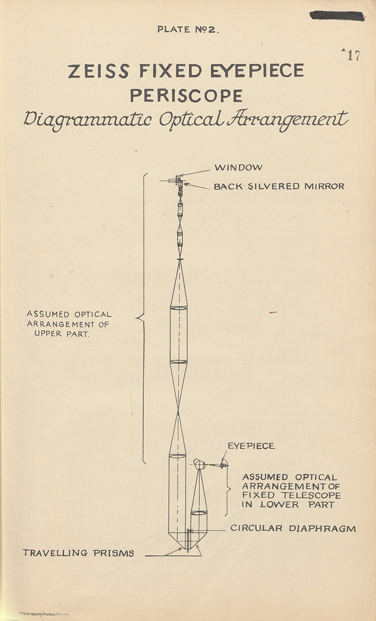
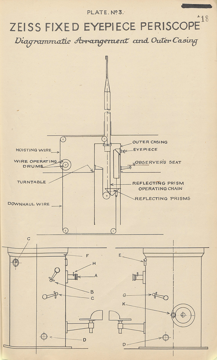
31 |
||||||||||||||
| 5. A downhaul wire is connected to the cradle carrying the prisms, to ensure the correct relative position between the upper and lower portions when hoisting or lowering. | ||||||||||||||
| 6. The hoisting and downhaul wires are operated simultaneously from the same spindle, but the diameter of the drum for the hoisting wire is twice that of the drum for the downhaul wire, to accommodate the difference in length of travel. | ||||||||||||||
| Optical Arrangement. (see Sketch 15028.) | ||||||||||||||
| 7. The sketch shows the probable arrangement of lenses and prisms within the periscope. In order to provide the fixed eyepiece arrangement, additional lenses are necessary. | ||||||||||||||
|
||||||||||||||
| 8. The top reflector gives an elevation movement of from - 15° to + 20°. | ||||||||||||||
| 9. The optical performance in both powers is satisfactory. | ||||||||||||||
| 10. The chief criticism is that the exit pupil is strongly chromatic at the side of the field. This gives the effect of changing colour of the field when eye is moved across the pupil. | ||||||||||||||
| 11. Light transmission appears to be good and to indicate that the internal surfaces are treated with cryolite or similar substances. It has not been possible to examine any of the internal surfaces except the top objective below the top reflector. The top surface of that objective showed definite signs of having been surface treated. | ||||||||||||||
Optical Performance |
||||||||||||||
12. The optical performance of this periscope may be compared with the Barr and Stroud periscopes of Type C.H. 57 unifocal and C.K. 8 bifocal, both of which have approximately the same qualities of definition. |
||||||||||||||
13. The definition in the centre of the field of the Zeiss instrument is good. Critical examination when the eye is moved across the exit pupil, however, reveals changes in quality which are not found in the Barr and Stroud instruments. |
||||||||||||||
14. With this reservation the quality of definition seen with the unaided eye from the centre of the field to a diameter of about two-thirds of the whole field is almost the same in the Barr and Stroud periscopes as in the Zeiss. Beyond that diameter the Zeiss periscope falls off very considerably, while the Barr and Stroud periscopes scarcely deteriorate at all. The Zeiss periscope falls off an important amount in definition in the lower power, while in the high power, although the definition is better near the edge of the field, there is a noticeable amount of distortion. |
||||||||||||||
15. The exit pupil is strongly coloured when viewed from the side. This is a defect which causes the side of the field to become reddish or bluish in colour when the eye is displaced slightly across the exit pupil. |
||||||||||||||
16. When the eyepiece is focused "in" the full amount, the sharp boundary of the field is lost; and it is replaced by an out of focus edge of smaller diameter. |
||||||||||||||
17. These latter two defects are not present in Barr and Stroud instruments. |
||||||||||||||
18. Optical adjustments for simultaneous focus of graticule and outside object are equally good in the Zeiss instrument and Barr and Stroud instruments. |
||||||||||||||
Colour Glasses |
||||||||||||||
19. Two colour glasses are provided which can be introduced singly or together near the focal plane of the eyepiece. One of the glasses is a bright orange and the other a very deep neutral. The neutral glass had the appearance of being a lightly metallisied glass. |
||||||||||||||
Controls. (See Sketch 15029.) |
||||||||||||||
20. The moving parts are all controlled from the eyepiece position. They are indicated diagrammatically on Drawing 15029. |
||||||||||||||
Focus adjustment by rotating eyepiece "A." |
||||||||||||||
Elevation and depression by moving the lever "B." |
||||||||||||||
Raising and lowering the periscope by means of the lever "C." |
||||||||||||||
A dial "C" indicates the position of the elevation, extremes on the dial being 9.3 and 14.6 metres. |
||||||||||||||
A separate handle is provided apart from the periscope for raising and lowering the periscope is desired. |
||||||||||||||
Bearing scale situated at "F." Bearing is also indicated on dials "E," where an adjustment is provided so that the dials can be set at any desired constant difference from the true bearing. |
||||||||||||||
Change of magnification controlled by the lever "G." |
||||||||||||||
| Colour glasses inserted by the lever "H." | ||||||||||||||
| The periscope does not embody a range estimator. | ||||||||||||||
32 |
|||||||||||||||||||||||||||||||||||||||||||||||||||||||||
Zeiss Periscope No. 2523 (Watchkeeping Periscope) |
|||||||||||||||||||||||||||||||||||||||||||||||||||||||||
| Optical Data | |||||||||||||||||||||||||||||||||||||||||||||||||||||||||
|
|||||||||||||||||||||||||||||||||||||||||||||||||||||||||
Graticule Reading - Low Power |
|||||||||||||||||||||||||||||||||||||||||||||||||||||||||
|
|||||||||||||||||||||||||||||||||||||||||||||||||||||||||
| Light at side of field cut down to about 30 per cent. of the light in the centre. | |||||||||||||||||||||||||||||||||||||||||||||||||||||||||
| Optical Performance | |||||||||||||||||||||||||||||||||||||||||||||||||||||||||
21. The corrections for flatness of field, astigmatism, coma and chromatism, are made to a good standard. |
|||||||||||||||||||||||||||||||||||||||||||||||||||||||||
22. The graticule is illuminated by luminous material carried in glass tubes around the edge of the graticule. The illumination begins to show on the graticule after about 12 seconds application of the eye to the eyepiece in the dark, and after about 3 minutes the divisions can be distinguished. The numbers cannot be read. |
|||||||||||||||||||||||||||||||||||||||||||||||||||||||||
Light Transmission |
|||||||||||||||||||||||||||||||||||||||||||||||||||||||||
23. The light transmission as measured by Barr and Stroud apparatus was: |
|||||||||||||||||||||||||||||||||||||||||||||||||||||||||
| |||||||||||||||||||||||||||||||||||||||||||||||||||||||||
24. All the optical parts, with the exception of the windows, the outside face of the eye lens and the surfaces in the focal planes, were treated with non-reflecting film. The film on the top prism was in bad condition and had to be cleaned off. The films seemed to be of much softer nature than those produced by British manufacturers. |
|||||||||||||||||||||||||||||||||||||||||||||||||||||||||
25. The compensating lens, top prism, high-power lenses, lower-power lenses, colour glasses and graticule objective, are all held in one frame. A differential movement causes the compensating lens to move at twice the angular speed of the prism so that the lens is always kept normal to the axis of the emergent beam. The high- and low-power lenses are mounted on a square box which can be rotated to introduce either the high-power system or the low-power system. The colour glasses flap in to the beam. Two glasses are provided, one of a bright orange and the other of a very dense neutral glass. |
|||||||||||||||||||||||||||||||||||||||||||||||||||||||||
26. The movements of the top prism with compensating lens, of the change of power and of the colour glasses, are controlled by six wires running the whole length of the periscope. The wires are moved by operating heads at the bottom. |
|||||||||||||||||||||||||||||||||||||||||||||||||||||||||
27. A reflector is provided above the bottom prism and can be switched into the beam when desired. The reflector is partially coated with aluminium to reflect light to a second eyepiece through a system of prisms. When the reflector is in place, therefore, the instrument can be used as a binocular periscope. The second eyepiece is removable, a window being provided to seal the periscope. |
|||||||||||||||||||||||||||||||||||||||||||||||||||||||||
28. The periscope is fitted with a bearings scale telescope, which is intended to make the indications of the bearings scale, visible in the main eyepiece. |
|||||||||||||||||||||||||||||||||||||||||||||||||||||||||
29. The periscope seems to be intended for night use particularly. This is indicated by the large exit pupil (7 mms.) which is the maximum diameter to which the pupil of the eye expands in complete darkness, and it is also indicated by the treatment of the optical surfaces by non-reflecting film. |
|||||||||||||||||||||||||||||||||||||||||||||||||||||||||
33 |
||||||||
Pressure Night Sight Binoculars |
||||||||
| 30. The binoculars were manufactured by Carl Zeiss, Visnna, and bear the numbers: | ||||||||
U.D.F. 7x50 |
||||||||
309 |
||||||||
170955 |
||||||||
| 31. The measured optical data: | ||||||||
|
||||||||
| 32. The focus is fixed, being set at --).8 dioptre in the centre of the field. | ||||||||
| 33. The central definition is good provided the observer has normal eyesight and a reasonable amount of accommodation. | ||||||||
34. The definition over the field of view is also up to a good standard. |
||||||||
35. The light at the side of the field is cut down severely by the optical parts. |
||||||||
36. Measured light transmission: |
||||||||
|
||||||||
37. Internal surfaces of the lenses are treated with Cryolite or some similar substance. |
||||||||
38. No coloured glasses are embodied in the instrument. |
||||||||
39. The weight of the instrument is |
||||||||
|
||||||||
Note. The weight of Pattern 1900C binocular with a rubber jacket is 3 lbs. 13 ozs. |
||||||||
40. A graticule is provided in the right limb. It consists of a vertical line which gradually thickens from the centre to the outside of the field. The line is provided with night illumination by a self-luminous placed in a compartment to the right of the graticule. There is an external lever which controls the illumination from "hell" (Bright" to "dunkel" (Dark). In the bright position the illumination is visible after 2 to 3 minutes' observation in the dark and plainly visible after 10 minutes. In the dark position it is just cut out completely. |
||||||||
41. The inter-ocular adjustment is effected by separating the limbs about the hinge by means of a bar and nuts with right- and left-handed threads. The amount of adjustment provided is from 54 to 74 mm. |
||||||||
Miscellaneous |
||||||||
Luminous Paint |
||||||||
The luminous paint is very good. It is visible immediately the lights are extinguished and so placed as to make it possible to move about without trouble. After a few minutes objects become visible. |
||||||||
Water Flow Meters |
||||||||
These are fitted in the trim line, the flooding line to the W.R.T. tanks and in the fine flood to 0 compensating tank. They are extremely accurate and have proved invaluable. |
||||||||
Night Sight |
||||||||
The night sight comprises a pair of pressure-tight binoculars mounted on a D.A. ring mounted on a bearing ring, which transmits the bearing to the torpedo director. The D.A. is calculated on the director and passed up to the Commanding Officer. Both bearing and D.A. rings have luminous figures and pointer. The whole is mounted on a pedestal situated centrally abaft the forward periscope. There being no periscope standards above the bridge level an excellent all-round view is obtained. This is a simple and excellent night sight. The luminous paint shows no sign of deterioration and little sign of wear. |
||||||||
| Berthing Facilities | ||||||||
| There are six pairs of disappearing bollards, spaced as follows: | ||||||||
| One pair close to bows and stern, one pair each side one-third of the submarine from forward and aft. The broad casing and the fact that the bollards are on top of it and not inside makes working wires a very simple matter. Ropes and wires are stowed in special free flooding boxes in the casing. | ||||||||
| Anchor and Cable | ||||||||
| There is only one anchor and 150 metres of cable. There are no means of parting the cable abaft the compressor so that the anchor has to be catted before a bridle can be prepared. | ||||||||
| 2. No "Brake Slip" is fitted but compressor ad brake are adequate. | ||||||||
| 3. As in British submarines, the anchor needs to be veered about 2 fathoms before it will drop. | ||||||||
|
||||||||
| (C50426) D | ||||||||
34 |
||
| Log | ||
| A pitometer type log is fitted. | ||
| Muffler Valve Grinding Gear | ||
| Since the silencers are completely dry (i.e., no spray of muffler valve baths are provided) and also, since the muffler valves must be shut when the engines are running in order to blow the exhaust tanks, the valves and seatings are metal to metal. In order to keep the muffler valves watertight under these conditions a grinding arrangement is fitted. | ||
| 2. The muffler valve is operated through a shaft carrying a bracket, the end of which is machined to carry a spherical carrier about which the valve can move. It can rotate freely and has a considerable amount of float in all directions. The periphery of the muffler valve has worm teeth cut in it and into these engages a short worm which is carried on the operating shaft. This worm is rotated by spur gears and shafting carried down through the pressure hull into the engine room. The worm and worm teeth are always in gear and the valve may be rotated when in any position. The power for rotation is obtained from a small air motor which is geared to the shaft and the speed of which is controlled by a centrifugal governor. The pressure used is 12 atmospheres (170 lbs. sq. in.). | ||
| 3. When running the engine it is necessary to turn the muffler valve frequently in order to keep the worm gear and spherical carrier free of carbon. On diving the muffler valve is shut hand tight and the grinding motor started, gradually tightening the muffler valve with a bar until it is watertight. | ||
| 4. A similar arrangement is fitted on the group exhaust valves, but this gear is hand operated. | ||
| 5. In the case of the Junker's air compressor exhaust valve, the valve floats on the end of the main spindle. It is rotated by an extension from the valve passing down the centre of the main spindle and is turned by hand. | ||
Electric Distiller |
||
This is a self contained apparatus in which a high degree of economy is realised. |
||
2. The distiller consists of a container, made small enough to pass through a hatch. The lower part of the container houses the brine and condensate coils. Feed water from a gravity tank supplied direct from the sea is led into the lower part through a ball-operated control valve. Heat is abstracted from the brine and condensate and the heated feed water passes into the upper chamber in which are the electric heating elements and the condenser. Above the container is mounted a rotary vapour pump which keeps a vacuum in the evaporator of approximately 6 inches. The vapour is pumped into the condenser where it is condensed by the feed water round it. The condenser is formed by a number of flattened coils, the flattening being arranged so that the coils may be kept clear of scale by scrubbers rotating between them. These scrubbers are driven from a carden shaft turned by an extension from the same electric motor which drives the vapour pump. The condensate flows from the condenser to a pig's ear and thence through an electric salinometer to the distilled water tank. The brine is pumped out of the evaporator by a pump driven from the end of the carden shaft and is discharged into a brine tank which can be emptied through the main line. |
||
3. The feed water takes about two hours to heat up from cold. When working one heater only need be kept on, this taking a current of about 6 amps. The vacuum is controlled by switching a second heater on or off as necessary. |
||
4. The average capacity of the apparatus is four gallons an hour. |
||
Tank blowing by Means of Exhaust Gas |
||
No L.P. blowers are fitted. The tanks are blown clear after surfacing by the engine exhaust at a pressure of .6 atmospheres or 8 1/2 lbs. sq. in. |
||
2. Between each engine group exhaust and muffler valve is a branch pipe closed by a valve which is controlled from the engine room. The two pipes marry after passing these valves and the single pipe is led to a distributing box, outside the pressure hull. Valves in this box distribute the air to the main ballast tanks, i.e., Nos. 1, 3 and 5 and Nos. 2 port and starboard, and 4 port and starboard fuel ballast tanks. The valves in the distributing box have extended spindles passing through the pressure hull and operated from the control room. The gas passes direct to Nos. 1, 3 and 5 main ballast tanks and through tankside valves situated in the casing in the case of the remaining tanks. The ends of the blow pipes are led to the lowest parts of the tanks and are bent upwards there. Some water is always left in the tanks and the ends of the pipes are therefore always covered. |
||
3. The blowing is carried out by opening the master blowing valve in the engine room and at the same time shutting the muffler valve. One ballast tank is blown at a time. The engine in use for blowing may be running light or propelling and is run at a speed of not less than 300 r.p.m. It is important that the master blow valve and the muffler valve should not be open at the same time. If they are, the tank will vent through the blow pipes and muffler valve, the speed of venting being increased by the flow of exhaust gas through the silencer. |
||
Telemotor System |
||
The telemotor system is employed only for raising and lowering both periscopes and training the after periscope. It is automatic in operation. |
||
2. There are two vertically mounted I.M.O. type pumps, one of them the main pump and the other the auxiliary pump. These take their suctions from a replenishing tank the level of oil in which varies between fixed limits. The pumps discharge into three air loaded accumulators which are pistonless, are not fitted with bye-pass valves, and have no air bottles attached to them. The telemotor pressure fluctuates between wide limits, depending on the volume of air in the accumulators. When full the pressure is 80 atmospheres (1,140 lbs. sq. in.) and the oil in the replenishing tank is at the |
||
35 |
||
| low level. The head of oil in the tank operates one of two bellows contacts, the contact being broken when the level of oil is at its lowest. As the periscopes are worked oil flows back into the tank until the pressure is reduced to 50 atmospheres (710 lbs. sq. ins.) and the oil level is at its highest. The head of oil than makes the contact through the bellows and the telemotor pump in use is started and continues running until the high pressure-low level condition is reached when the contact breaks and the pump stops. An auxiliary replenishing tank is fitted by means of which the oil level in the main tank may be adjusted. | ||
| 3. The motors operating the periscopes are Imo type pumps and are started through relay and pilot valves. Automatic cut-outs controlling the pilot valves adjust the strokes of the periscopes. | ||
| 4. The main telemotor pump is used normally, and the auxiliary pump, the starter of which is near the main blowing panel, is used should the cut-outs fail to operate. Bye-pass relief valves are fitted on each pump but do not come into action unless the cut-outs fail. | ||
| Oxygen System | ||
| Ten interconnected bottles, each of 50 litres capacity, are fitted to supply oxygen. There are three in the torpedo stowage space, four in the control room, two in the engine room and one in the after ends. Each bottle has its own shut-off valve and an isolating valve is fitted at each bulkhead. | ||
| 2. Oxygen is used for the following purposes: | ||
| (i) To supply gas to the exhaust ventilation system when the vessel is dived and air is being circulated. The air is drawn from the compartments through three banks of C.O.2 absorbent canisters, one set in the control room and one in each of the torpedo compartments. | ||
| (ii) Direct to the compartments through reducing valves and a water trap, the latter enabling the amount of oxygen passing to be checked. The gauge on the low pressure side of the reducer is marked "Mann" and presumably is so calibrated that the amount of oxygen supplied can be regulated according to the number of men in the compartment. | ||
| (iii) To supply the oxygen bottles contained in the German equivalent of D.S.E.A. sets. This is fitted in the control room. | ||
3. The oxygen bottles are recharged through an outboard connection on the forward side of the bridge casing. |
||
H.P. Air Valves |
||
These valves have packingless glands, the glands being sealed by a collar on the spindle making continuous contact through a celluloid washer with spindle brush. The valve end of the spindle is squared and is bored to act as a guide for the valve. The squared end turns a screwed sleeve which carries the valve. By this arrangement the only force to be overcome in working the valve is that due to the friction between the spindle collar and brush and this is small enough to enable the valve to be opened, or shut by hand. Excessive pressure is not, therefore, exerted on the valve and valve seating and the contact between them can be kept to a knife-edge. |
||
2. The spindle, valve and removable valve seatings are made of stainless steel. The spindle sleeve and screwed sleeves are brass. The valve body is made of stainless iron. |
||
3. The group valves on the H.P. manifold are arranged with a non-return as well as a full open position. |
||
4. Filters are fitted in each group supply pipe to the H.P. manifold. |
||
Salvage Blows |
||
L.P. air connections are fitted on the after sides of the bridge casing. These connections may be used for two purposes: |
||
(i) To supply air to the compartments direct. One connection then acts as a supply and the other as an exhaust. Air connections are also fitted to the fore and after ends. |
||
(ii) To supply air to a group of blow cocks, through a master cock, fitted at the forward end of the bridge casing. The blow cock handles are made with rings denoting the tank to which they are connected. No. 3 M.B. tank blow is connected directly to the exhaust blow pipes, Port and Starboard. Nos. 2 and 4 Port and Starboard salvage blows join their respective exhaust blow pipes but have to pass the external tank-side blow valves. Nos. 1 and 5 M.B. tank salvage blows are led through the pressure hull past valves which may be opened either inside or outside the submarine. They join the direct blow pipes in the control room. Tankside blows are fitted when the blow pipes pass through the ends of the pressure hull. |
||
Pumping and Trimming System |
||
There is one main ballast pump and one trimming pump. |
||
2. There is no "main line" as designed in British submarines. A cluster of valves at the pump and a valve box in the forward part of the control room "feed" all tanks forward of the control room with the exception of the W.R.T. tanks, which have their suction valves in the torpedo compartment. Each tank forward of the control room has its own suction line and valve. Abaft the control room a "main line" is fitted with suctions off it to No. 1 battery tank, slop drain tank, two engine room bilge suctions, motor room bilge suction and the after W.R.T. tank. |
||
3. A separate trimming line between the forward and after trim tanks is fitted. In this is incorporated an accurate flow meter and a trim "cock." The trim cock enables the trim pump to pump from forward to aft and vice versa. This system allows the movement of water from one end of the |
||
(C50426) E |
||
36 |
|||||||||||||||||||||||||||||||||||||||||||||||||||||||||||||||||||||||||||||
| ship to the other to be gauged with extreme accuracy and renders change of trim, necessitated by movement of personnel, extremely simple. The trim pump can also be used on all other tanks through a suction pipe led into the main ballast pipe suction. The trim cock being in a central position enables water to be blown instead of pumped. | |||||||||||||||||||||||||||||||||||||||||||||||||||||||||||||||||||||||||||||
| 4. The trim and ballast lines are made of all welded steel and all valves are cast steel. It is never necessary to use a wheel spanner. | |||||||||||||||||||||||||||||||||||||||||||||||||||||||||||||||||||||||||||||
| H.P. Air Line | |||||||||||||||||||||||||||||||||||||||||||||||||||||||||||||||||||||||||||||
| There are six groups of air bottles totalling twelve bottles. Nos. 1, 2 and 6 groups are located externally in the casing, No. 3 in the E.R.A.'s mess, Nos. 4 and 5 groups in the torpedo compartment. The bottles are charged by a Junkers diesel air compressor and a Krupp electric air compressor. | |||||||||||||||||||||||||||||||||||||||||||||||||||||||||||||||||||||||||||||
| 2. The working pressure is 205 atms. and the air line is made of copper, external diameter 11/16 in., internal diameter 7/17 in. | |||||||||||||||||||||||||||||||||||||||||||||||||||||||||||||||||||||||||||||
| 3. Leads from all air groups are brought to a high pressure air column in the control room. From this column leads go to: | |||||||||||||||||||||||||||||||||||||||||||||||||||||||||||||||||||||||||||||
| (i) Direct blow for main ballast column. | |||||||||||||||||||||||||||||||||||||||||||||||||||||||||||||||||||||||||||||
| (ii) Blow to auxiliary tanks. | |||||||||||||||||||||||||||||||||||||||||||||||||||||||||||||||||||||||||||||
| (iii) Air to the L.P. panel. | |||||||||||||||||||||||||||||||||||||||||||||||||||||||||||||||||||||||||||||
There is also a shore charging connection. |
|||||||||||||||||||||||||||||||||||||||||||||||||||||||||||||||||||||||||||||
4. An air line running forward feeds the capstan, torpedo charging and torpedo firing reservoir; an air line running aft feeds the torpedo charging and firing reservoir aft. Air for mine firing is taken direct from Nos. 1 and 6 air groups, and can also be taken from the H.P. air column if the column is opened up to Nos. 1 and 6 groups and the groups shut off. Engine starting can be taken in a similar manner from No. 2 group or the H.P. column. |
|||||||||||||||||||||||||||||||||||||||||||||||||||||||||||||||||||||||||||||
L.P. Air System |
|||||||||||||||||||||||||||||||||||||||||||||||||||||||||||||||||||||||||||||
H.P. air from the H.P. column is brought to an L.P. air column in the control room. The column is connected to: |
|||||||||||||||||||||||||||||||||||||||||||||||||||||||||||||||||||||||||||||
(i) Trim tank line. |
|||||||||||||||||||||||||||||||||||||||||||||||||||||||||||||||||||||||||||||
(ii) D/F mast. |
|||||||||||||||||||||||||||||||||||||||||||||||||||||||||||||||||||||||||||||
(iii) Weed clearing blow on main line sea flood. |
|||||||||||||||||||||||||||||||||||||||||||||||||||||||||||||||||||||||||||||
(iv) Hydroplane clutches. |
|||||||||||||||||||||||||||||||||||||||||||||||||||||||||||||||||||||||||||||
(v) Whistle. |
|||||||||||||||||||||||||||||||||||||||||||||||||||||||||||||||||||||||||||||
(vi) Air driven tools. |
|||||||||||||||||||||||||||||||||||||||||||||||||||||||||||||||||||||||||||||
2. An L.P. air line forward feeds W.C., indicator buoy, bow buoyancy tank and blows to the tubes and W.R.T.s; and air line aft feeds after indicator buoy, weed clearing blows in port and starboard main circulating water inlets, after W.C., oil fuel regulating tanks, muffler valve grinding gear, engine clutches, weed clearing blows in after circulating water discharge and inlets, after buoyancy tank, after torpedo tube and W.R.T. |
|||||||||||||||||||||||||||||||||||||||||||||||||||||||||||||||||||||||||||||
CHAPTER VII |
|||||||||||||||||||||||||||||||||||||||||||||||||||||||||||||||||||||||||||||
CONSTRUCTION AND MAIN ENGINES |
|||||||||||||||||||||||||||||||||||||||||||||||||||||||||||||||||||||||||||||
Engineering |
|||||||||||||||||||||||||||||||||||||||||||||||||||||||||||||||||||||||||||||
Particulars of Ship |
|||||||||||||||||||||||||||||||||||||||||||||||||||||||||||||||||||||||||||||
|
|||||||||||||||||||||||||||||||||||||||||||||||||||||||||||||||||||||||||||||
37 |
||||||||||||||||||||||||||||||||||||||||||||||||||||||||||||||
| Hull | ||||||||||||||||||||||||||||||||||||||||||||||||||||||||||||||
| The hull is of all welded construction, the only riveting being on the engine room cover plate and the flanges of the dished ends of No. 3 main ballast tank. | ||||||||||||||||||||||||||||||||||||||||||||||||||||||||||||||
| 2. The frames are of bulb section bars with no flanges. There are 82 frames. | ||||||||||||||||||||||||||||||||||||||||||||||||||||||||||||||
| 3. The thickness of the pressure hull plating is 0.88 in., decreasing to 0.63 in. towards the ends. | ||||||||||||||||||||||||||||||||||||||||||||||||||||||||||||||
| 4. The keel is 1.8 ft. high and 3.6 ft. wide. It is free flooding and iron ballast is carried at the ends. | ||||||||||||||||||||||||||||||||||||||||||||||||||||||||||||||
| 5. The thickness of the pressure plating of the conning tower is 1.26 in. | ||||||||||||||||||||||||||||||||||||||||||||||||||||||||||||||
| 6. The endings of the pressure hull are formed with dished plates which carry the housings of the torpedo tubes. The thickness of these endings is 1.378 in. | ||||||||||||||||||||||||||||||||||||||||||||||||||||||||||||||
| 7. Internally, the vessel is sub-divided by W.T. bulkheads into six compartments. The bulkheads enclosing the control room are dished, the remainder are flat with rectangular doors and are of comparatively light construction. | ||||||||||||||||||||||||||||||||||||||||||||||||||||||||||||||
| 8. The bulkheads of No. 3 main ballast tank are .83 in. thick and are dished in the opposite direction from those of the control room. This tank is tested to full diving pressure, i.e., the kingstons need not be shut when going deep. The well for the forward periscope and the tube for the attack periscope which houses the reflector prisms are contained in No. 3 M.B. tank. The vent pipes for the tank are carried from the crown of the tank at each side through hand-worked intermediate vents to the two main vents in the casing. | ||||||||||||||||||||||||||||||||||||||||||||||||||||||||||||||
| 9. Nos. 1 and 5 main ballast tanks are free flooding and are controlled by hand worked vents, operated from the control room with secondary positions over the forward and after tubes. | ||||||||||||||||||||||||||||||||||||||||||||||||||||||||||||||
10. The forward and after buoyancy tanks have locally operated vents and blows, in the forward and after compartments. |
||||||||||||||||||||||||||||||||||||||||||||||||||||||||||||||
11. Capacities of all tanks are given in the following tables: |
||||||||||||||||||||||||||||||||||||||||||||||||||||||||||||||
Compartments in Submarine (See also W.T. Compartments). Sketch Plan No. 17322/13. |
||||||||||||||||||||||||||||||||||||||||||||||||||||||||||||||
|
||||||||||||||||||||||||||||||||||||||||||||||||||||||||||||||
Tanks and Capacities |
||||||||||||||||||||||||||||||||||||||||||||||||||||||||||||||
|
||||||||||||||||||||||||||||||||||||||||||||||||||||||||||||||
38 |
||||||||||||||||||||||||||||||||||||||||||||||||||||||||||||||||||||||||||||||||||||||||||||||||||||||||||||||||||||||||||||||
Tanks and Capacities - continued |
||||||||||||||||||||||||||||||||||||||||||||||||||||||||||||||||||||||||||||||||||||||||||||||||||||||||||||||||||||||||||||||
|
||||||||||||||||||||||||||||||||||||||||||||||||||||||||||||||||||||||||||||||||||||||||||||||||||||||||||||||||||||||||||||||
Auxiliary Tanks |
||||||||||||||||||||||||||||||||||||||||||||||||||||||||||||||||||||||||||||||||||||||||||||||||||||||||||||||||||||||||||||||
|
||||||||||||||||||||||||||||||||||||||||||||||||||||||||||||||||||||||||||||||||||||||||||||||||||||||||||||||||||||||||||||||
| *Admiralty Technical Report on U-570 says 25.3 tons but this seems to be an error. ONI report with original Design and Specification Books say 47.75 tons |
39 |
||||||||||||||||||||||||||||||||||||||||||||||||||||||||||||||||||||||||||||||||||||||||||||||||||||||||||||||||||||||||||||||
Auxiliary Tanks continued. |
||||||||||||||||||||||||||||||||||||||||||||||||||||||||||||||||||||||||||||||||||||||||||||||||||||||||||||||||||||||||||||||
|
||||||||||||||||||||||||||||||||||||||||||||||||||||||||||||||||||||||||||||||||||||||||||||||||||||||||||||||||||||||||||||||
| External Oil Fuel Tanks | ||||||||||||||||||||||||||||||||||||||||||||||||||||||||||||||||||||||||||||||||||||||||||||||||||||||||||||||||||||||||||||||
| There are two on each side of the ship, formed in the ends of the external plating. | ||||||||||||||||||||||||||||||||||||||||||||||||||||||||||||||||||||||||||||||||||||||||||||||||||||||||||||||||||||||||||||||
| 2. They are each fitted with four kingstons, hand-worked from two positions for each group. The tanks are blown from the direct flow manifold in the control room through tankside blow valves or from the engine exhaust blow system through distributing valves in the control room and tankside valves in the casing. The exhaust blow pipes pass to the bottoms of the tanks. | ||||||||||||||||||||||||||||||||||||||||||||||||||||||||||||||||||||||||||||||||||||||||||||||||||||||||||||||||||||||||||||||
| 3. The compensating water pipes are led from the expansion tank in the conning tower casing through double-seated valves to the small expansion tanks fitted at the bottoms of the fuel tanks. The double seated valves must be either in connection with the expansion tank or with the sea. The expansion tank is always in open connection with the sea and thus the fuel tanks are always equalised and the only compensating water pressure which can be applied is that due to the head of water in the expansion tank. This arrangement is necessary where direct blows are fitted and avoids the possibility of straining the tanks due to high pressures. The tanks are built of light plating and are tested to 15 lb. per sq. in. | ||||||||||||||||||||||||||||||||||||||||||||||||||||||||||||||||||||||||||||||||||||||||||||||||||||||||||||||||||||||||||||||
| 4. The two port and the two starboard tanks are connected in pairs by a pipe leading to a common vent on each side of the conning tower in the casing. Each single tank is isolated by a tank top vent operated from inboard and an intermediate vent operated from the upper deck. When in use as fuel tanks the main vents are opened on diving and the tank top vents are kept shut as long as fuel is in the tanks. This equalises the pressure in the pipe between the tank and the vent. | ||||||||||||||||||||||||||||||||||||||||||||||||||||||||||||||||||||||||||||||||||||||||||||||||||||||||||||||||||||||||||||||
| 5. Nos. 2 port and starboard tanks are cross-connected by a pipe at their after ends leading through intermediate valves to a common vent. This main vent is operated from the control room and the intermediates from the upper deck. | ||||||||||||||||||||||||||||||||||||||||||||||||||||||||||||||||||||||||||||||||||||||||||||||||||||||||||||||||||||||||||||||
| 6. Connections are led from the tanks as follows: | ||||||||||||||||||||||||||||||||||||||||||||||||||||||||||||||||||||||||||||||||||||||||||||||||||||||||||||||||||||||||||||||
(i) Inboard vent pipes through the hull to a pigs-ear via duplicate shut-off valves. |
||||||||||||||||||||||||||||||||||||||||||||||||||||||||||||||||||||||||||||||||||||||||||||||||||||||||||||||||||||||||||||||
(ii) Transfer pipes, through duplicate valves to the oil fuel transfer valves. |
||||||||||||||||||||||||||||||||||||||||||||||||||||||||||||||||||||||||||||||||||||||||||||||||||||||||||||||||||||||||||||||
(C50426) F |
||||||||||||||||||||||||||||||||||||||||||||||||||||||||||||||||||||||||||||||||||||||||||||||||||||||||||||||||||||||||||||||
40 |
||||||||||||||||||||||||||||||||
MAIN ENGINES |
||||||||||||||||||||||||||||||||
| There are two sets of G.W. 4-cycle engines, built by Blohm and Voss under Krupp licence at Hamburg. There are 6 cylinders to each engine. | ||||||||||||||||||||||||||||||||
|
||||||||||||||||||||||||||||||||
| They are direct injection with Bosch type pumps and injectors. | ||||||||||||||||||||||||||||||||
| 2. The power developed is: | ||||||||||||||||||||||||||||||||
| 1,400 B.H.P. at 470 r.p.m., which is normal full power and give a nominal speed of 17 knots. | ||||||||||||||||||||||||||||||||
| 1,600 B.H.P. at 490 r.p.m., which is the maximum overload and gives a nominal speed of 17.8 knots. | ||||||||||||||||||||||||||||||||
| 3. The engines are reversible and are pressure-charged by engine-driven superchargers of the Root's type. | ||||||||||||||||||||||||||||||||
|
||||||||||||||||||||||||||||||||
4. The cylinder blocks are cast in sections of three units, each which are bolted to each other and mounted on the bearing frames to which they are secured by long bolts. A wrapper plate is welded to the bearing frames to form the engine sump. |
||||||||||||||||||||||||||||||||
The order of firing is: |
||||||||||||||||||||||||||||||||
| ||||||||||||||||||||||||||||||||
5. Valve settings: |
||||||||||||||||||||||||||||||||
| ||||||||||||||||||||||||||||||||
CAPACITIES OF ENGINE ROOM AUXILIARIES |
||||||||||||||||||||||||||||||||
Lubricating Oil Pump - Auxiliary |
||||||||||||||||||||||||||||||||
| ||||||||||||||||||||||||||||||||
Circulating Water Pump - Auxiliary |
||||||||||||||||||||||||||||||||
| ||||||||||||||||||||||||||||||||
Lubricating Oil Separator |
||||||||||||||||||||||||||||||||
| ||||||||||||||||||||||||||||||||
Details of Auxiliary Machinery |
||||||||||||||||||||||||||||||||
Pump for Lubricating Exhaust and Induction Valve Stems |
||||||||||||||||||||||||||||||||
| ||||||||||||||||||||||||||||||||
Cylinder Oil Pump |
||||||||||||||||||||||||||||||||
| ||||||||||||||||||||||||||||||||
41 |
|||||||||||||||||||||||||||||||||||||||||||||||||||||||||||||||||||||||||||||||||||||||||
|
|||||||||||||||||||||||||||||||||||||||||||||||||||||||||||||||||||||||||||||||||||||||||
| Operation of Main Engines | |||||||||||||||||||||||||||||||||||||||||||||||||||||||||||||||||||||||||||||||||||||||||
| Starting air is stored in two bottles of 200 litres capacity, one behind each engine; the bottles are charges through a reducing valve from the main line to a pressure of 30 atms. | |||||||||||||||||||||||||||||||||||||||||||||||||||||||||||||||||||||||||||||||||||||||||
| Interlocks | |||||||||||||||||||||||||||||||||||||||||||||||||||||||||||||||||||||||||||||||||||||||||
| (i) The engine cannot be started with the blower clutched in. | |||||||||||||||||||||||||||||||||||||||||||||||||||||||||||||||||||||||||||||||||||||||||
| (ii) The reversing lever cannot be moved unless the fuel lever is at stop. | |||||||||||||||||||||||||||||||||||||||||||||||||||||||||||||||||||||||||||||||||||||||||
| (iii) The starting lever cannot be moved unless the reversing lever is at Ahead or Astern. | |||||||||||||||||||||||||||||||||||||||||||||||||||||||||||||||||||||||||||||||||||||||||
(iv) The fuel lever cannot be moved to a position above that required to give a speed of about 420 r.p.m. until the blower is clutched in. |
|||||||||||||||||||||||||||||||||||||||||||||||||||||||||||||||||||||||||||||||||||||||||
2. The induction trunk normally takes its air through two ports which are automatically shut when the blower clutch is engaged. |
|||||||||||||||||||||||||||||||||||||||||||||||||||||||||||||||||||||||||||||||||||||||||
3. Air for the engine is normally brought to it through an outboard induction pipe with its inlets at the highest part of the bridge screen, approximately 4 ft. 6 in. above the conning tower hatch. The two leads are married into a valve just above the hull and abaft the conning tower trunk. This valve is operated from the control room. The hull valve is between the engines and near the starting platform. The inboard lengths of the trunk are taken round the hull and down to approximately the level of the crankshaft. |
|||||||||||||||||||||||||||||||||||||||||||||||||||||||||||||||||||||||||||||||||||||||||
4. Lubricating oil is stored in two reserve tanks of 3,250 litres capacity each. Between these are the drain tanks, one to each engine, and each hold 800 litres. |
|||||||||||||||||||||||||||||||||||||||||||||||||||||||||||||||||||||||||||||||||||||||||
5. The engine-driven lub.-oil pumps, which are of the gear type with automatic change-over valves for astern running, take their suction from these tanks. The engine bearing pressure if 1 atm. The maximum capacity of each pump is 380 litres/min. (23cu. m./hour) (5,000 galls./hr.). A cooler and filter are provided in the lubricating system of each engine, the coolers being fitted with bye-passes for temperature control. The strainers are of the Auto-Klean type. |
|||||||||||||||||||||||||||||||||||||||||||||||||||||||||||||||||||||||||||||||||||||||||
6. There is also a lub.-oil purifier which takes its suction from each drain tank and the dirty lub.-oil tank. It has a water-washed bowl, the water being normally taken from the engine circulating system and then passed through an electrical heater. There are two gear pumps incorporated with the separator, one pumping clean oil from and the other dirty lub. oil to the machine. The capacity is 300 litres/hour (66.2 galls/hour). |
|||||||||||||||||||||||||||||||||||||||||||||||||||||||||||||||||||||||||||||||||||||||||
One auxiliary lub.-oil pump is fitted and this can also be used for pumping fuel. |
|||||||||||||||||||||||||||||||||||||||||||||||||||||||||||||||||||||||||||||||||||||||||
7. Circulating water is taken through double sea inlets, one each side of the starting platform, by engine-driven pumps of the bucket type, one to each engine. The maximum capacity of each pair of pumps is 400 litres/min. (57.2 cu./hr) (5,300 galls./hour). |
|||||||||||||||||||||||||||||||||||||||||||||||||||||||||||||||||||||||||||||||||||||||||
(C50426) F2 |
|||||||||||||||||||||||||||||||||||||||||||||||||||||||||||||||||||||||||||||||||||||||||
42 |
||
| 8. The circulating water is led through coolers and the the bottoms of the liners. The discharge is led to the group exhaust and muffler valves and tanks, and thence to an expansion tank at the after end of the conning tower casing which forms the compensating water supply to the external oil fuel groups. Fuel oil is compensated into two overhead gravity tanks of capacity of 400 litres, passing through a filter in the process. From the gravity tanks it passes through a flowmeter which can be bye-passed, and then to the fuel boost pump, which can also be bye-passed. The oil then passes through an Auto-Klean type filter and so the the fuel pumps. | ||
| Cylinder Blocks and Frames | ||
| The cylinder blocks, two to each engine, are held down to the frames by 14 anchor bolts, nutted at each end. The centre pair of bolts hold the ends of the two blocks where they abut. The cylinder blocks are also bolted to the girder frames by a number of bolts through flanges cast on the blocks and frames. There are 25 of these on each side of the engine, 12 of which are fitted. The size of the bolts is 7/8 in. | ||
| 2. The top nuts of the anchor bolts are sunk into the cylinder blocks and the recess is covered by a light steel plate. The lower nut is housed in the bulbous top of the frame which is reduced to a single smaller section below to which the sump plate is welded. | ||
| 3. The cylinder blocks form the water jackets of the liners which make a ground water-tight joint at the top of the block. The bottom water joint is made by two rubber rings. Baffles are formed round the tops of the jacket spaces to ensure adequate cooling for the top of the liner. | ||
| The main bearings are held down by jacks which are screwed through bridges taking under a projection on the engine frames. There is one jack bolt to each bearing. | ||
| Two spare bridges are carried, one for No. 4 bearing which is wider due to the junction of the two cylinder blocks. | ||
| Four spare main bearing shells and one spare crankhead bearing are carried. | ||
Cylinder Heads |
||
The cylinder heads are made from a high grade cast iron of the "Emmel" type. They are provided with a large cooling space and six inspection doors. |
||
2. The test pressure of the cooling space is 10 kgs./sq. cms. (142 lb./sq. in.) and the underside of the explosion head is tested to 70 kgs./sq. cms. (994 lb./sq. in.). |
||
3. The heads are held down by 8 in no. studs screwed into the cylinder block. The inboard pair of studs are shorter than the remainder and allow the cylinder head to clear when removing it. The distance is made up by long sleeve nuts. |
||
4. Each head carried the two fulcrum brackets for the exhaust and induction valve rocker arms; the air starting valve which carries its own fulcrum pin; a relief valve and the injector. |
||
5. The water service discharge from the head is lead to the exhaust valve box through a cock which allows the water to circulate in series or parallel through the valve box. |
||
6. The exhaust and induction connections to the manifold are on the outboard side of the head. |
||
7. The bumping clearance of the piston is 7 mm. designed. |
||
8. The head has a spigot formed on the underside which makes the gas-tight joint on the copper ring in the liner groove. |
||
9. The weight of the head is 290 kgs. (640 lbs.). |
||
10. Nos. 6 port and 1 starboard have been examined and were found to be in good condition. |
||
11. One spare cylinder head is carried. |
||
Main Engine Liners |
||
The cast iron liners are seated into the cylinder block on a ground joint. The gas joint is made by a copper ring in a groove in the top of the liner. The bottom water joint is made by two rubber rings. |
||
2. The weight of a liner = 222 kgs. (492 lbs.). |
||
3. The test pressure is 20 kgs./sq. cm. (285 lb/sq. in.) except for the upper 140 mms. which is tested to 60 kgs./sq cm. (855 lb./sq. in.). |
||
The minimum hardness of the liner material is 200 Brinell. |
||
4. Cylinder lubrication is by means of a Grutzner pump with two connections to each liner, inboard and outboard. |
||
There are no oil grooves cut in the liner walls and no holes are provided for piston slinging gear. |
||
43 |
||||||||||
| Main Engine Pistons | ||||||||||
| 1. The aluminium alloy pistons have flat dished tops and are uncooled. | ||||||||||
| 2. They are fitted with six impulse rings, one upper scraper ring and two slotted scraper rings. Drain holes are drilled behind the two lower scraper rings and also in the oil catchment grooves. The grooves, two in number, are situated immediately below each slotted scraper ring. | ||||||||||
| 3. The gudgeon is held tightly in the piston by taper plugs at each end which open the ends out against steel brushes in the piston. The plugs are held in place by circlips. | ||||||||||
| 4. The gudgeon pin plugs are extracted by means of an hydraulic jack placed against each plug in turn. When these are removed the pin may easily be pushed out of the piston. The plugs are replaced by the same hydraulic jack. | ||||||||||
| 5. In assembling, the pin is replaced with the slots at the bottom, and the plugs are so fitted as to hold the pin tightly at 150-160° C. | ||||||||||
| 6. Nos. 6 Port and 1 Stbd. pistons have been withdrawn and examined. All rings were free and in good condition. There were no signs of ring flutter or blow past. Such carbon as was present was soft. | ||||||||||
| Connecting Rods | ||||||||||
| The connecting rod has a large diameter bore through it, being reduced near the eye end of the rod. The lubricating oil is taken round the gudgeon brush and fed through the pin through four holes at 45° above and below the horizontal. | ||||||||||
Fuel Injection Pumps |
||||||||||
These pumps are manufactured by M.A.N. to Bosch license. The quantity of oil discharge is regulated by the effective stroke of the plunger before spill port is uncovered, this being controlled by turning the plunger. Automatic injection timing is provided in the pump plungers. This is arranged by making the leading edge of the plunger wedge-shaped from the "no-fuel" position to a point 30° towards the "full fuel" position. |
||||||||||
2. All the pumps are linked together through a spring-controlled rod operated by the fuel lever on the engine control. The after end of this rod is connected to a spring-loaded piston through a relay valve which is also operated by the overspeed governor, which is held in its working position by the lubricating oil pressure. Should this pressure fail, the spring forces the rod back and so cuts off the fuel delivery from the pumps. |
||||||||||
3. The maximum effect stroke of the pump is 20 mms. The diameter of the oil inlet to the pump is 6 mms. |
||||||||||
4. A relief valve is fitted to the pump discharge which is set to 650 kgs./sq. cm. (9,220 lb./sq. in.). |
||||||||||
5. The discharge valve is fitted with a plain part below the seat to counteract the effect of the swelling of the fuel pipe under pressure and thus ensure a quick cut-off at the end of the injection and avoid dribbling at the injector nozzle. |
||||||||||
6. The pumps are cam-driven, working against heavy springs. |
||||||||||
7. An overspeed governor is fitted connected by bell-crank levers to the pump control rod and cutting out the fuel delivery in the same way as the lubricating oil pressure control. |
||||||||||
8. No. 6 starboard pump was removed by the German crew due to the tappet guide being broken. |
||||||||||
9. The following spare gear for fuel pumps was carried: |
||||||||||
| ||||||||||
Injectors |
||||||||||
Fitted in the centre of the cylinder head in a watertight tube. |
||||||||||
2. They are fitted with a vent connection and a drain pipe. The injectors are of the Bosch type and the nozzles are multiholed. The holes are 5 mms. diameter, 10 in number and the included angle is 150°. The strike of the needle valve is 1 mm. |
||||||||||
3. The spring is so loaded so as to allow the valve to lift at a pressure of 300 atms. (4,500 lb./in. sq.). |
||||||||||
4. A test pump is carried. |
||||||||||
5. Six in number spare injectors were carried, and also four in number fuel pipes. |
||||||||||
Relief Valves |
||||||||||
Fitted at the outboard side of the cylinder head. They are set to lift at 75 atms. (1,125 lb./in. sq.). |
||||||||||
2. Three relief valves are carried as spare. |
||||||||||
| (C50426) F3 | ||||||||||
44 |
||||||||||||||||||||||
| Exhaust and Induction Valves | ||||||||||||||||||||||
| There is one exhaust and induction valve to each unit, fitted with single parallel springs. The exhaust valve boxes are water-cooled with water from the cylinder heads. A vent pipe is taken from the highest point of the water outlet pipe and led to a common visible discharge. | ||||||||||||||||||||||
| 2. The stems of both exhaust and induction valves are lubricated by a mechanical pump driven from the camshaft. | ||||||||||||||||||||||
| 3. Both exhaust and induction valve springs are of the same size, but the materials of which the valves are made are different. | ||||||||||||||||||||||
| 4. The details of the springs are as follows: | ||||||||||||||||||||||
|
||||||||||||||||||||||
| 5. The internal diameter of valve seat id 150 mms. Valve lift, 40 mms. | ||||||||||||||||||||||
| 6. The valves are fitted with false seats which make the gas joints in the cylinder heads by means of round section copper rings. | ||||||||||||||||||||||
| 7. The test pressure of the cooling space of the exhaust valve is 10 kgs. sq. cm. (142 lb/sq. in,). | ||||||||||||||||||||||
|
||||||||||||||||||||||
Air Starting |
||||||||||||||||||||||
Starting air is stored in two bottles, one at the back of each engine. They are charged from the air system at 30 atms. The capacity of each bottle is 200 litres. |
||||||||||||||||||||||
2. When the starting lever is moved air is admitted to control valves mounted above the air starting main valves and the push rods are depressed on the cams. As the shaft revolves the roller on the end of the push rod follows a reverse cam and the main valve is thus forced open. The valves open at top centre and the period is 130° of crankshaft revolution. |
||||||||||||||||||||||
3. The air to the control valves is taken through a shut-off valve. |
||||||||||||||||||||||
4. A relief valve is fitted at the end of the air starting pipe. |
||||||||||||||||||||||
5. The stroke of the valve is 12 mms. |
||||||||||||||||||||||
6. Three air starting valve boxes complete are carried, and also three valves. |
||||||||||||||||||||||
Reversing |
||||||||||||||||||||||
The reversing gear consists of the following parts: |
||||||||||||||||||||||
(i) A valve box, containing three valves and operated by the starting lever on the engine control. |
||||||||||||||||||||||
(ii) A change-over valve comprising two pistons on a common piston rod; the upper piston controlling the passage of oil and the lower the passage of air. |
||||||||||||||||||||||
(iii) The air and oil passing through the change-over valve operate the pistons of the main reversing cylinder, the upper piston again working with oil and the lower with air. |
||||||||||||||||||||||
(iv) A replenishing oil tank fitted with spring loaded delivery and return valves. |
||||||||||||||||||||||
(v) A lay shaft, revolved by means of a rack and pinion by the movement of the piston rods of the main reversing cylinder. This shaft carries an eccentric sheave and strap which moves the engine camshaft axially. |
||||||||||||||||||||||
(vi) A crankshaft driven by gearing from the layshaft (5) the movement of the crank turning, by means of gearing, another shaft lying parallel to the engine camshaft and to which the roller ends of the valve push rods are connected eccentrically. The turning of this shaft causes the push rod ends to be drawn away from the camshaft, thus freeing the cams from their rollers and allowing the axial movement of the camshaft to bring the rollers to the astern cams. |
||||||||||||||||||||||
2. The actual work of reversing is carried out by air pressure from the starting air bottles, the oil piston of the main reversing cylinder acting as damper to prevent a too violent movement of the gear. |
||||||||||||||||||||||
3. The hand reverse gear consists of hand pump which transfers oil to the oil end of the main reversing cylinder through a discharge valve, the displaced oil from the other side of the piston returning through another valve in the pump body. |
||||||||||||||||||||||
45 |
||||||||
| 4. The reversing mechanism is interlocked with the pressure charger clutch handle so that the clutch cannot be engaged with the engine running astern and also with the starting lever so that the engine cannot be started unless the reversing lever is in the "Ahead" or "Astern" positions. | ||||||||
| 5. Positions are marked on the starting lever as follows: | ||||||||
|
||||||||
| Engine Clutches | ||||||||
| The clutches are of the double cone friction type made by Lohmann and Stolterfoht A-G. | ||||||||
| 2. The driving surfaces are complete cones of friction lining. The cones are engaged by means of bell crank levers and expanding links which break centre to hold the clutch when engaged. The bell crank levers are worked from the clutch operating sleeve on the motor shaft which has a total stroke of 88 mms. This sleeve is air operated, with a secondary hand operation, and above the air plunger is a guide bar carrying spring loaded flanges at its ends. When the plunger is moved to the limit of its travel and the air is released from the operating cylinder these springs carry the flanges and so the sleeve strap arm back in the reverse direction. This causes the sleeve strap to be freed from the sleeve collar and prevents heating. The stroke between the working positions is thus reduced to 75 mms. | ||||||||
| 3. The clutches are adjusted by means of a toothed wheel turning a rack which alters the distance between centres of the clutch cone pins. A graduated ring is fitted below the adjusting wheel to facilitate setting. | ||||||||
| 4. The stroke of the clutch cone guides on the driving pins is 10 mms., i.e., each cone moves 10 mms. between the "in" and "out" positions. This stroke is measured by means of a setting bar with a loose collar by which the distance between the back of the locking nut on the driving pin and the cone guide brush may be ascertained. | ||||||||
| 5. Two oil level plugs are fitted on the clutch casing, which allow the oil level to be determined. | ||||||||
6. Both engine clutches seized in the engaged position shortly after the engines were first run. It is considered that this was caused by the flooding of the engine room which caused water to enter the clutch casings and swell the friction linings. In each clutch the after cone was seized. These were jacked off the driving faces of the female cone and the linings were dried out. The clutches were then reset. |
||||||||
Supercharger |
||||||||
Air for supercharging is supplied from a Root's blower situated at the after end of the engine at cylinder height and driven by gearing from the shaft. |
||||||||
2. The blower consists of two parallel rotors, each with two vanes and each vane carried in three bearings, the after one being a location bearing. |
||||||||
3. The clearance between the rotors and casing at 15° C. is .30-.45 mms. The end clearance is .60-.65 mms. on the driving side and .30-.35 mms. on the opposite side. |
||||||||
4. The blower is engaged by a lever operated from the starting platform, the operation of this lever also shutting off the rotary valves in the induction trunk. This lever is interlocked with the starting lever so that the engine cannot be started with the blower engaged. |
||||||||
5. The blower clutch is of the double cone friction type and a flexible coupling is incorporated in the gear train in order to damp out any torsional effects. This coupling consists of two members connected by springs with a friction plate. |
||||||||
6. The blower is connected at speeds above 390 r.p.m. or at corresponding powers. An interlock prevents the engine being run at more than a pre-determined power unless the blower is engaged. |
||||||||
7. The pressure of the supercharging air varies from .23-.3 atmospheres, depending on the speed. |
||||||||
8. The volume of air supplied = 1.1 x Swept volume. |
||||||||
Main Mounting |
||||||||
Motor Shafts |
||||||||
The motors are carried on two bearings which form the motor thrusts in addition. The diameter of the motor shafts is 224 mms. |
||||||||
2. On the after ends of the motor shafts are the tail clutches. These are double cone friction clutches of the same type as the engine clutches but are hand operated. |
||||||||
3. The full travel of the rail clutch strap is 77 mms. and the working travel 65 mms. |
||||||||
(C50426) F4 |
||||||||
46 |
|||||||||||||||||||||||||||||||||||||||||||||||
| Tail Shafts | |||||||||||||||||||||||||||||||||||||||||||||||
| The tail shafts are 175 mms. diameter, 80 mms bore. | |||||||||||||||||||||||||||||||||||||||||||||||
| 2. They are carried in two stern tubes each, the outer ends being supported by "A" bracket bearings. The stern glans are formed on the forward sides of the after W.R.T. tank. The shafts have liners shrunk on them, the external diameter being 195 mms. The tube bearings and "A" bracket bearings are lined with strips of material which analysis indicates belongs to the Phenolic Aldihyde class. The material which is reinforced with canvas is similar in general characteristics to Tufnol. The designed clearance is 1 mm. The length of each stern bush is 550 mms. The diameter of the liners over the tail shafts in the way of the "A" bracket is 220 mms. the shaft diameter being 180 mms. The length of the "A" bracket bush is 535 mms. The average shaft clearance with the bushes dry is .006 in. (as measured in dry dock.). | |||||||||||||||||||||||||||||||||||||||||||||||
| 3. The exposed part of the tail shafts between the after stern bushes and the "A" bracket bushes is wrapped with wire and canvas. | |||||||||||||||||||||||||||||||||||||||||||||||
| Note. There is a loose coupling connecting the thrust and tail shafts. | |||||||||||||||||||||||||||||||||||||||||||||||
| Thrust Shafts | |||||||||||||||||||||||||||||||||||||||||||||||
| The thrust shafts carry the main thrust blocks and bearings. | |||||||||||||||||||||||||||||||||||||||||||||||
| 2. The thrusts are Michell type, each with 10 pads and the working clearance is .023 in. Nineteen spare pads are carried. | |||||||||||||||||||||||||||||||||||||||||||||||
| 3. The brakes are hand operated through a detachable ratchet lever and are ferodo lined. The brakes are fitted on the tail shafts aft of the coupling. | |||||||||||||||||||||||||||||||||||||||||||||||
Cooling |
|||||||||||||||||||||||||||||||||||||||||||||||
The motor bearings and the main thrusts are water cooled, either from the motor room circulating pump or from the engine circulating water system. It is necessary to supply water to these bearings at all but the lowest speed. |
|||||||||||||||||||||||||||||||||||||||||||||||
2. The main motor coolers are also supplied from these two sources. (The bends through which the air flows from the motors to the coolers are liable to accumulate water. This can be pumped out through fitted stand pipes, one to each bend, a hose being supplied to fit these. A semi-rotary pump is stowed in the after ends for this purpose. |
|||||||||||||||||||||||||||||||||||||||||||||||
Propellers |
|||||||||||||||||||||||||||||||||||||||||||||||
The propellers are of cast steel. |
|||||||||||||||||||||||||||||||||||||||||||||||
2. They were originally coated with a resinous varnish which was worn off during the time the vessel was beached. The parts thus exposed have corroded badly and up to the present no satisfactory form of preservative coating has been found. Analysis shows that the nearest equivalent coating is seaplane varnish to specification 2X17. |
|||||||||||||||||||||||||||||||||||||||||||||||
3. The details of the propellers are: |
|||||||||||||||||||||||||||||||||||||||||||||||
|
|||||||||||||||||||||||||||||||||||||||||||||||
Circulating Water System |
|||||||||||||||||||||||||||||||||||||||||||||||
The circulating water pumps are fitted in pairs at the forward ends of each engine. They are engine driven from the crankshafts. |
|||||||||||||||||||||||||||||||||||||||||||||||
2. The main inlets are fitted at each side of the starting platform and are in duplicate, the inner valve being a sluice. There is a common suction to each pair of pumps and there is also a common delivery pipe and a common air vessel. A relief valve is fitted in each discharge, the water from this relief passing to the bilge. |
|||||||||||||||||||||||||||||||||||||||||||||||
3. A throttle valve is fitted in the suction side in order to regulate the amount of water pumped. |
|||||||||||||||||||||||||||||||||||||||||||||||
47 |
||||||||||||
| 4. The water passes from the inlets to a distributing box thence to the pumps. From the pumps it passes through the discharge distributing box and so to the coolers, which can be bye-passed. From the coolers it is led to the cylinders. The discharge from the liners passes through an external pipe to the cylinder heads, through which there is a positive flow over the explosion plate and round the injector tube. The discharge from the head is led through a pipe with branches to the exhaust valve by means of which the cooling water can flow in series or parallel through the valve box, or in any amount between these two conditions. At the highest point of the system, i.e., on the discharge from the exhaust valves and on the exhaust bends, vents are fitted. | ||||||||||||
| 5. The cooling water flows round the exhaust manifold, the group exhaust jacket, and thence to jacketing round the muffler valve and silencer. Finally it is led to a gravity tank in the after side of the bridge casing where it is used to compensate fuel from the external and internal O.F. tanks. | ||||||||||||
| 6. A loop valve is fitted between the exhaust manifold jacketing and the pump inlets in order to give a heat control. | ||||||||||||
| 7. The maximum discharge temperature should not exceed 50° C. and the temperature rise should not exceed 25° C. | ||||||||||||
| 8. A cooling water pump is fitted in the motor room and can supply water to the engines after diving if necessary. | ||||||||||||
| 9. There are connections for pumping round anti-corrosion oil by means of the hand cooling water pump, but no oil was found in the boat. | ||||||||||||
| 10. An auxiliary circulating water pump is fitted. The details are: | ||||||||||||
|
||||||||||||
| Lubrication System - Main Engines | ||||||||||||
Lubricating oil is stored in two reserve and two drain oil tanks and there is a dirty oil tank for spoilt oil. |
||||||||||||
2. The positions and capacities of these tanks are: |
||||||||||||
| ||||||||||||
3. The starboard reserve lubricating oil tank is marked No. 1 and the starboard drain oil tank is the forward one of the two drain tanks. |
||||||||||||
4. Each engine has its own drain oil tank, the returns to the tanks from the engines being regulated by a double-seated valve, in order to keep the same level in each tank when the systems are cross-connected. |
||||||||||||
5. The discharge from the engine-driven pumps passes to a distributing box, thence to the coolers through strainers. A duplex gauge is fitted to the strainers showing the pressure of the inlet and outlet oil. A hand-regulated bye-pass valve is fitted to the discharge from the pump returning to the engine drain oil pipe. A vent cock is fitted to the top of each cooler, also connected to the drain oil pipe. The pressure outlet from the coolers at about 3 atms. is led to the engine services through a hand-regulated reducing valve, reducing the pressure to 1.5 atms. The oil supplies the main bearings and from them the crankheads and gudgeon pins, the vibration dampers, the pressure chargers, the camshafts and the fuel injector pump cut-out regulator. |
||||||||||||
6. A hand pump is fitted taking its suction from either of the reserve tanks and is used to top up the clean oil ready use tank on the forward bulkhead of the engine room. |
||||||||||||
7. The main engine-driven pumps are of the gear wheel type driven from the crankshaft and fitted with automatic change-over valves for astern running. They may be primed from the engine supply pipe when the reserve oil pump is running. |
||||||||||||
8. The purifier takes suctions from the two drain oil tanks or the dirty oil tank returning the cleaned oil to either of these tanks. A heater is fitted for warming the oil before it passes through the centrifuge and another heater is fitted for heating the sea water used for washing the bowl. |
||||||||||||
9. The lubricating oil filling connection is above the engine room and the oil passes through a hull valve and a strainer to the reserve oil pump distribution box and so to the reserve or drain oil tanks. |
||||||||||||
10. Both engine lubricating oil systems may be cross-connected and thermometers are fitted in the pump discharge lines before and after the coolers. |
||||||||||||
11. Capacity of each pump: 23 cu. m./hour (5,200 galls./hr.). |
||||||||||||
48 |
||||||||||||||||||||||||||||||||||||||||||||||||||||||
| Oil Fuel System | ||||||||||||||||||||||||||||||||||||||||||||||||||||||
| Oil fuel is carried in the following tanks: | ||||||||||||||||||||||||||||||||||||||||||||||||||||||
|
||||||||||||||||||||||||||||||||||||||||||||||||||||||
The gravity tanks hold 700 litres each (154 galls.). |
||||||||||||||||||||||||||||||||||||||||||||||||||||||
| 2. There is also a dirty fuel oil tank at frames 25-26 and its capacity is 425 litres (94 galls.). | ||||||||||||||||||||||||||||||||||||||||||||||||||||||
| 3. The total capacity is thus 131,350 (29,000 galls.) litres or 109 tons at 266 gallons per ton. | ||||||||||||||||||||||||||||||||||||||||||||||||||||||
| 4. Nos. 1 and 2 internal O.F. tanks are compensated from the expansion tank which is supplied from the engine circulating system. | ||||||||||||||||||||||||||||||||||||||||||||||||||||||
| 5. The external O.F. tanks are compensated from the engine circulating water discharge from the muffler tanks to an expansion tank. The water passes down to the tank through a double-seated valve which admits water to the tank either from the expansion tank or from the sea. The external tanks are fitted with 4 in No. hand operated kingstons to each tank and common hand-worked vents are fitted to Nos. 2 and 4 port and 2 and 4 starboard. These common vent pipes are also fitted with isolating valves at the tank tops. Nos. 2 port and starboard tanks have a cross vent pipe at their after ends, fitted with isolating valves and leading to a common master vent valve. This is used when the fuel tanks are in use as main ballast tanks. | ||||||||||||||||||||||||||||||||||||||||||||||||||||||
| 6. When in use as fuel tanks red plugs are fitted on the ends of the kingston handles preventing the kingston spanners being shipped. Similarly, the blow valves are sealed and the after end vent master valve to Nos. 2 port and starboard is locked. | ||||||||||||||||||||||||||||||||||||||||||||||||||||||
7. The compensating water to the external O.F. groups is led into a built-in tank at the bottom of the external and thence into the tank through a syphon pipe. |
||||||||||||||||||||||||||||||||||||||||||||||||||||||
8. These fuel tanks are fitted with direct H.P. blows and L.P. blows from the engine exhaust. |
||||||||||||||||||||||||||||||||||||||||||||||||||||||
9. The regulating tanks are non-compensated, fuel being transferred to the gravity tanks by air. The air pressure is controlled from the engine room through a reducing valve supplying air at .5 atms. The tanks may also be blown from the control room at 12 atms. Gauge glasses are fitted in the control room to establish the amount of oil in the tanks. |
||||||||||||||||||||||||||||||||||||||||||||||||||||||
10. All tanks are filled from a hose connection on the hull over the engine room through a hull valve and strainer to the distributing box and so through the tank filling valves to the respective tanks. The usual method of filling is by gravity but the oil may be pumped in by the reserve oil pump through hose connections. |
||||||||||||||||||||||||||||||||||||||||||||||||||||||
11. The tank blow-outs are led through selector cocks and hull valves in the case of the internal tanks and through tank top valves in the external tanks. These lead to cocks discharging into pigs ears in the casing. The regulating tanks vent into pigs ears in the control room. |
||||||||||||||||||||||||||||||||||||||||||||||||||||||
12. Test valves are fitted to each of the external tanks, led into pigs ears in the engine and control rooms. The internal tanks are also fitted with a testing gear which measures the amount of oil in the tanks through the stand pipe leading into the selector cock and so into a bucket. The gear operates in the same manner as the Scott's measuring gear. The graduated measuring glass is fitted in the engine room permanently and is calibrated for both internal tanks. |
||||||||||||||||||||||||||||||||||||||||||||||||||||||
13. There is no method of blowing the internal tanks, the fuel being pumped out through a hose fitted to a connection on the compensating water line and to the oil fuel distributing box. This box has connections to the reserve lubricating oil pump which are normally blanked off. The tanks may also be pumped out by means of a hose connected to the main ballast pump suction line. |
||||||||||||||||||||||||||||||||||||||||||||||||||||||
14. A flowmeter is fitted in the filling line and this may also be employed to record the amount of fuel passing from the tanks to the gravity tanks. A flowmeter is fitted between the gravity tanks and the engines. The fuel supply to the engines passes to a booster pump, which may be bye-passed, this supplying the injector pumps after passing through a fine filter. |
||||||||||||||||||||||||||||||||||||||||||||||||||||||
15. The external tanks may be blown out through the distributing box and a hose connection to the filling connection on the casing. |
||||||||||||||||||||||||||||||||||||||||||||||||||||||
16. The gravity tanks are fitted overhead on the cover plate and there is a change over cock which puts one tank in connection with the engine supply rail and the other in connection with the compensated fuel line. |
||||||||||||||||||||||||||||||||||||||||||||||||||||||
17. The dirty oil tank is pumped out by the hand cooling water into the compensating water line and so to any internal tank. |
||||||||||||||||||||||||||||||||||||||||||||||||||||||
18. Relief valves are fitted on each of the internal O.F. tanks. |
||||||||||||||||||||||||||||||||||||||||||||||||||||||
49 |
||
Description of the Junkers Free Piston Diesel Compressor |
||
| Construction | ||
| The Diesel engine portion is situated in the centre, the compressors are arranged on the outside. The two groups of pistons running in opposite directions are connected with one another, swing free outwards and inwards, and thus have no mechanical limitation of stroke. In practice, however, a determined maximum stroke is not exceeded due to cushioning, but in the event of a breakdown copper screws are provided to absorb the impact of the pistons. | ||
| Method of Operation | ||
| For starting up, compressed air is directed on the pistons brought into the outside position. The pistons now speed towards the centre and compress in the engine cylinder the combustion air. Hereupon fuel is injected into the combustion air heated by high compression. By means of combustion which occurs the pistons are driven apart. In doing so, a part of the air enclosed in the compressor is pressed into the scavenging air receiver as scavenging air for the engine through the scavenging valves. The remainder of the air, after passing the scavenging valves, is compressed further to the working pressure of the compressor and is pushed out through the delivery valves. The working pressure in the compressor is maintained by means of a pressure retaining valve even when the reservoir pressure fluctuates. At the outer ends of the strokes the scavenger and exhaust ports are uncovered by the engine pistons which are brought to rest by the compressed air. This forces the pistons together again and compresses the air between them in readiness for the next cycle. | ||
| Control | ||
| Since the pistons have no mechanical limitation of stroke, the stroke of the pistons is controlled automatically by changing the amount of fuel injected. The more fuel there is injected into the engine the quicker the pistons fly apart and the more compressed air is delivered. At "no load" the compressor runs at 810 cycles per minute. When pumping against full pressure, i.e., 205 atms., the speed increases to 850 cycles per minute. | ||
50 |
||
APPENDIX I |
||
COPY OF LIEUTENANT COLVIN'S REPORT OF PROCEEDINGS |
||
Subject: Ex-German Submarine "U 570" - Report of Proceedings |
||
| From: Lieutenant G. R. Colvin, R.N., Temporarily in Command H.M. Submarine "U 570." | ||
| To: The Flag Officer (Submarines), Northways, London. | ||
| Date: 3rd October, 1941. | ||
| The following report dealing with the refloating of the ex-German Submarine "U 570" from Thorlak Red Beach, Iceland; her preparation for the journey to the United Kingdom; and her passage under my command from Hvalfjord, Iceland, to Barrow, is submitted. Attached is enclosure to this report. | ||
2. Party composed of myself, Warrant Engineer Giordan, R.N., E.R.A. (III) Crook and Act. P.O. (L.T.O.) Patterson with Mr. Davies (civilian representative from H.M. Signal School) and Mr. Mitchell (civilian representative from N.I.D.) arrived at Reyjavik by air at 2000 on Saturday, 30th August. A conference was held by Admiral Commanding Iceland, at 2100 that night, at which he gave us all the information at his disposal concerning the "U 570" which had been beached at Thorlak Red in a sinking condition. A.C.I.C. stated that salvage operations were in preparation and that it was hoped to bring the submarine into Hvalfjord where she could be made seaworthy for towing to the United Kingdom. It was decided that I should be made responsible for giving the submarine as much buoyancy as possible for refloating, and for making her seaworthy for towing to Hvalfjord. |
||
3. The party left Reykjavik at 0800 on Sunday, 31st August, and, guided by S.O.(I) to A.C.I.C., proceeded to Thorlak Red. Here we took a local boat to H.M.S. "Burwell" (this being the ship of the senior officer of Operation Graph) and we were then able to go on board the "U 570" by Burwell's whaler, through breaking surf, at about 1300/31. |
||
4. The submarine was then lying broadside on to the surf and listing heavily to starboard (i.e. inshore). She was on a gently shelving beach of very soft sand, completely open to the south-east, and had been driven well up the beach by a moderate swell. The interior of the submarine was unlit and was in a chaotic state; leaks of oil and water from the broken gauge glasses of internal tanks had combined with vast quantities of provisions, flour, dried peas and beans, soft fruit, clothes, bedding, and the remains of scores of loaves of black bread to form a revolting morass that in places was knee-deep. It was subsequently discovered that in this ship the crew's w.c. had been converted into a food locker and overturned buckets of excrement added to the general noisome conditions. |
||
5. Mr. Staker, Gunner (T) of the "Burwell," was on board engaged in searching the ship for demolition charges; he had already searched the control room and all forward compartments, and after our arrival continued his search in the after compartments. No charges were found. Mr. Staker was subsequently lent to me for the operation and gave assistance at all times. |
||
6. An examination of the ship was first made by hand-lamps, after which the lighting was restored by P.O. Patterson for the first time since the ship was depth-charged. Work was then commenced to lighten the submarine for refloating and make her seaworthy for towing. |
||
7. During the afternoon of Monday, 1st September, I proceeded to Reykjavik on board H.M.S. "Burwell" and reported the condition of the submarine to A.C.I.C., and that night made a written report to him to the effect that the submarine's pressure hull was water-tight, her machinery apparently undamaged and although handicapped by lack of compressed air and battery power, I was confident that she could be given sufficient buoyancy to make it safe to float her and tow her to Hvalfjord, she could be prepared for passage to the United Kingdom under her own power. On Tuesday morning I returned on board the submarine and that evening was appointed temporarily in command of the submarine by signal from A.C.I.C. |
||
8. A summary is given here of the work done on board the submarine between p.m. Sunday, 31st August, and 0500 Friday, 5th September: |
||
(a) Lighting was restored by temporary repairs to supply fuze holders. Lighting remained poor owing to lack of power, numerous broken fittings, and many earths. |
||
(b) Shut and cottared main vents. Shut off all bulkhead valves, voice pipes, ventilation valves, pet-cocks, etc., and checked shut all inlets, discharges, group exhausts and other valves in the engine room. Shut all valves and cocks in casing. Tubes were tested and found dry, with bow caps shut. |
||
(c) All flooding and suction, trimming and main line connections and systems were traced and shut. |
||
(d) Ballast pump, trimming pump and electric air compressor were tried but power was insufficient to operate them. It was ascertained that no ship in company could provide enough power through suitable leads to operate these auxiliaries, nor was there sufficient air hose for compressed air to be provided. |
||
(e) H.P. air system was traced. About 30 atmospheres remained in these groups. Some H.P. air and a lot of time was wasted in a vain attempt to start the Junkers diesel air compressor; it was afterwards discovered that the German crew had failed to maintain this most useful and important auxiliary in running order. An attempt was made to get H.P. air from the torpedoes, but all the accessible torpedoes were found to be electric. The torpedo firing reservoirs and the engine air-start bottles were empty. |
||
(f) With the H.P. air remaining: |
||
Nos. 2 port and starboard and No. 4 starboard tauchbunkers were blown. |
||
No. 4 starboard tauchbunker was partially blown. |
||
No. 3 tauchzelle was blown but a leak in the port side of this tank could not be stopped. |
||
No. 1 tauchzelle was blown, but much buoyancy was afterwards lost through a leaky vent to this tank. |
||
No. 5 tauchzelle, being holed, was not blown. |
||
All Kingstons and connections to these tanks were then shut. The Kingstons, especially on the starboard side, were very stiff to operate and no positive "feel" when the valves seated could be detected; it was thought that most of them had been badly strained by depth-charges or by pounding on the beach. |
||
All H.P. air was thus exhausted. |
||
(g) A small portable semi-rotary hand-pump (German) was then rigged in the engine room and about 10 tons of water was pumped out of the bilges. The pump was then shifted to the control room and the bilges pumped out; Nos. 2, port and starboard regelzelles, and No. 1 starboard regelbunker, were drained into the control room bilges through broken gauge glasses and so pumped overboard by hand. For'd and after trim tanks were then partially drained and pumped overboard. |
||
(h) Hand steering was rigged and tried. |
||
51 |
||
| 9. An attempt was also made to improve conditions inside the submarine and much food, clothes and bedding was disembarked and the worst of the filth was shoveled into buckets and jettisoned. While the above work was in progress Mr. Davies was examining the wireless equipment and the S.O.(I) to A.C.I.C. together with Mr. Mitchell was removing papers, etc. | ||
| 10. At about 0500 on Friday, 5th September, in fine and calm weather, the submarine was hauled off the beach by the salvage tug "Salvonia" with Lieutenant-Commander Watchlin, R.N.R., in charge of salvage operations. The submarine floated with more buoyancy than I had expected, but with a list to starboard of about three degrees and down by the bows. A corvette was then brought close alongside and an air hose was floated across from an Ingersoll portable low pressure air compressor, which Lieutenant-Commander Watchlin had obtained. The air hose was connected to the shore charging valve on the deck of the submarine, and Nos. 1, 2 and 5 tauchzelles were blown satisfactorily, and Nos. 2 and 4 port and starboard tauchbunkers were blown partially; the torpedo-operating tanks were blown through the main line, and all the air groups were charged to 80 lbs./in. - the maximum obtainable from the compressor. | ||
| 11. At 1300/5th towing started. I judged it advisable for myself, Mr. Giordan, Mr. Straker and the two ratings to remain onboard the submarine in case it might again be necessary to blow the tanks, and we were obliged to remain on deck where cold was severe as the air inside the submarine was by this time scarcely breathable. The weather remained favourable, the towing was accomplished without incident and the submarine was brought safely alongside H.M.S. "Helca" in Hvalfjord at 0930 on Saturday, 6th September. | ||
| 12. On the arrival of the submarine alongside "Helca" the Captain of that ship was placed in charge and he rendered a preliminary report on the condition of the "U 570" on 6th September, followed by an amplifying report on 19th September. Both reports were addressed to A.C.I.C. For the sake of continuity the preparation of the submarine for her voyage to the United Kingdom is here briefly described: | ||
| The submarine was first ventilated and cleaned by seamen who worked in shifts for 48 hours. The hull and underwater fittings were examined by divers, who patched the leak in No. 3 main ballast. Strong-backs were fitted to hold shut two leaking main vents. The H.P. air was fully charged and all tanks were blown. The batteries were pumped free of acid, and flushed out; and a single battery strapped up from the good cells remaining in the two main batteries. The gyro compass was repaired, all electrical circuits examined and a W/T set installed. | ||
| The port engine was run light on 10th September and the starboard on the 12th. A satisfactory charge was run on the starboard engine on the 14th. | ||
| On Monday, 15th September, successful trials were carried out under way; engines were run at speeds up to 350 revs./min. On the 16th, 17th and 18th a total of 17 hours charging was done and the starboard engine was returned. Further motor and engine trials were carried out on the 20th and the engines were worked up to 420 revs./min. with the superchargers in, giving a speed of 14 1/2 knots; on this day the Junkers diesel air compressor was run for the first time. | ||
| The crew (sent from the United Kingdom) joined on the evening of the 21st and trials and manoeuvres were carried out on the 22nd and 23rd. Hand steering was practised and the 2 cm. A.A. gun was fired. Stores, fuel, fresh water and provisions were embarked on the 24th September and on Thursday, 25th September, the ship was ready for sea. | ||
| 13. On 25th September, Admiralty approval having been given, a torpedo was disembarked and turned over to the United States Navy. It being impracticable to disembark any of the torpedoes stowed internally (not enough freeboard to open torpedo embarking hatches in the prevailing weather conditions) one of the upper-deck water-tight containers was disembarked complete with its torpedo. | ||
| 14. The submarine, escorted by H.M.S. "Saladin," left Hvalfjord on the afternoon of Monday, 29th September, passing through the boom at 1600. On clearing the land a moderate swell was met and the submarine, being down by the head and having naturally fine lines for'd with a broad flat casing, showed a marked tendency to return to periscope depth; engines were, however, worked up to 410-420 revs./min. with the superchargers in (giving a legend speed of about 15 knots) and these revolutions were maintained throughout the ocean passage and until 1800/2nd October. The weather on the ocean passage was mainly unfavorable with moderate sea and swell from the south and south-west, and with fresh to strong winds and rain, but an average speed of 12.8 knots was made good between Iceland and the Minches. | ||
15. The Butt of Lewis was rounded at 1950/1st October. Going south through Minches was a very strong head wind with short seas was encountered and the bridge extraordinarily uncomfortable with continuous heavy spray driving over. On entering the Irish Sea on the afternoon of the 2nd the weather eased to a flat calm and speed was reduced to 10 knots at 1800 in order to make Barrow after dawn on the 3rd. |
||
16. Entered Barrow Harbour at 1030 on Friday, 3rd October, and secured in Ramsden Dock at 1300. |
||
(Signed) G. R. COLVIN |
||
Lieutenant, R.N. |
||
Enclosure to Lieutenant Colvin's Report |
||
Ex-German Submarine "U 570" - Report of Proceedings |
||
STATE OF SUBMARINE WHEN ABANDONED |
||
1. Damage attributable to Depth-charges. Hull. The hull has not yet been examined in dry dock, but it is known that there is a split about 2 in. in length in the port side amidships (opening into No. 3 tauchzelle - an internal main ballast tank); the bow casing is crumpled slightly on each side and there are holes in the forward main ballast tank. There are minor leaks from the seams of internal oil fuel tanks into the submarine. Most of the Kingstons are damaged or strained, but whether by depth charges or by grounding is not known. |
||
Batteries. In the forward tank 21 cells out of 62 are cracked, all the damage being on the starboard side. In the after tank 26 cells are cracked, the damage being mainly on the starboard side and the two corners of the port side. |
||
Supply to Lighting and Auxiliaries. These circuits are fed from two pairs of 500-amp. fuzes (one pair being on each of the two battery supply switches). The concussion had broken one fuze holder on each supply, allowing the fuze to drop out; this at once cut off all the lighting and deprived every auxiliary machine of its power. |
||
Supply to Main Motors. The battery supply switches to the main motor switchboards jumped off, but were undamaged. |
||
52 |
||
| Other Damage. Remaining damage caused by the depth-charges was slight and consisted of: | ||
| Several broken gauge glasses to trimming and fresh water tanks. | ||
| Several lights broken. | ||
| Some of the more delicate electrical gear broken (automatic voltage regulators, etc.). | ||
| About four fuze boxes sprung open and porcelain heads of fuzes broken. | ||
| A few minor bracket welds sheared. | ||
| Shallow depth-gauge in control room damaged. | ||
| In engine room many glass domes over oil strainers broken. | ||
| 2. Summary of Damage. There is nothing in the hull damage which would make it impossible, or even difficult, to dive the submarine. Similarly the cracked cells in the batteries, although they would have caused a lot of trouble later, would not at the time have prevented the submarine from diving. | ||
| None of the other damage is of a nature to interfere with diving of the submarine. | ||
3. Steps taken by crew to overcome Damage. The German crew appear to have taken no steps whatever to cope with the situation caused by the depth-charges. |
||
The supply to the main motors could have been restored at once by re-making the battery supply switches. This was not done. |
||
The supply to the lighting and auxiliaries could have been restored: |
||
(a) In a few minutes by lashing up the broken fuze holders, and then replacing the fuzes. This was done by P.O. Patterson and his repairs answered admirably; or |
||
(b) In a few seconds by operating the change-over switches which give these circuits an alternative supply from the main motor switchboards. (To do this the battery supply switches must be made first.) |
||
Apparently no attempt was made to do this. |
||
The secondary lighting hand-lamps had been switched on and left run down. |
||
No attempt had been made to put the steering or 'planes in hand. |
||
H.P. air had been used so lavishly that only 30 atmospheres remained in three (out of six) groups. |
||
The German crew reported that the after part of the submarine was full of chlorine gas and they had, in fact, shut off the after control room bulkhead and ventilation valves. No trace of gas was noted, nor was there reason to suppose that there had ever been salt water in the after battery. (It is possible that the Germans merely "invented" the gas as an inducement to the British to rescue them quickly.) |
||
4. Steps taken by the Crew to Sink their Ship and Destroy Gear. No scuttling charges were placed. |
||
In the engine room the cover had been removed from a strainer in the circulating water system so that, by opening the main inlet, the engine room would have rapidly flooded. It is possible that some flooding was carried out by this means for there was a large quantity of water in this compartment; on the other hand, this may have been entirely due to a leak caused by the muffler valves being unseated by concussion (the muffler valve drains being open). |
||
There was no other evidence of an attempt to sink the submarine. |
||
Considering that the crew remained on board for over 24 hours after surrendering they succeeded in doing remarkably little damage to the submarine. |
||
The sabotage was chiefly in the wireless room, where many valves were smashed as well as the panels of the sets. The hydrophone (?) panel in the control room was also smashed but not completely. |
||
The attack instrument (fruit machine) in the conning tower was damaged by hammer blows on the dials. |
||
The Anschutz was damaged by unscrewing the pivots of the gymbals and allowing the compass to fall to the bottom of the casing. The damage was easily repaired in "Hecla." |
||
The dials of the deep diving gauges in the control room and conning-tower were defaced and damaged; the deep gauges in fore and after ends are similar but were untouched. |
||
The forward periscope was lowered into its well and the well filled with water and oil. A binocular attachment (?) on this periscope was removed and thrown overboard. |
||
No other damage has been discovered. |
||
5. Maintenance of the Submarine by the German Crew. Although the submarine was practically brand new there were already signs that the crew had not been skilful in upkeep and maintenance work. These points are here summarised: |
||
(a) The Engines were found to be considerably out of tune. |
||
| (b) The Junkers diesel air compressor had several defects and was not in running order. | ||
| (c) The slip to release the towing pendant has a wire pull to operate it from the bridge; as rigged this wire would not have released the slip. | ||
| (d) The eye-splice on the towing pendant was deplorable. It was spliced as a soft eye with only one tuck, then slipped over the thimble and seized up close with seizing wire to make it look convincing. | ||
| (e) One cell in the after battery was not properly strapped up. Of the five straps each side the studs had been left off from three on one side and two on the other. The bad contacts so caused had melted the bolts and straps. | ||
| (f) The main batteries were poorly maintained. The strap terminals were not vaselined and cells needed wiping over. | ||
| (g) The spare torpedoes in the crew space were not properly secured and the four lower torpedoes had slipped forward against some grease drums stowed in the "trenches" and stove in the drums. | ||
| 6. Conclusions. It would appear that the Germans surrendered their ship under the impression that she was more badly damaged than she in fact was. The fact that all the lights went out, the main and auxiliary motors stopped and water rushed into several compartments (from gauge glasses) may well have caused a most discernable panic. | ||
| It is, however, very difficult to understand why (when the crew had at least four hours of lying on the surface guarded only by one Hudson aircraft which was then armed only with machine-guns) no attempt was made in slow time to access the actual damage, repair it, dive, and escape. | ||
| (Signed) G. R. COLVIN | ||
| Lieutenant, R.N. | ||
53 |
||
APPENDIX II |
||
REPORT BY COMMANDING OFFICER, H.M.S. "HELCA" |
||
| The following report on the Anschutz compass in "Graph" is forwarded: | ||
| Condition on Inspection | ||
| The element had left its gimbal pivots and was found lying in the bottom of the casing. The element was lifted and on inspection it was found that the athwartships pivots were loose in the gimbal, giving the impression that these pivots had been unscrewed in an effort to sabotage. | ||
| 2. The crashing of the element in the base of its housing had severed the pipes of the water cooling system and had torn out some of the electrical cable. | ||
| 3. The element was replaced in its pivot. Its lid was then removed and the inside inspected. The sphere and cooling jacket appeared to be in good condition. | ||
4. It was impossible at this stage to state whether any damage had occurred inside the sphere and this being sealed was left untouched. It was considered unnecessary to fit the spare sphere until tests had been carried out on the compass. The parts were replaced and the joints remade. |
||
5. The flexible water pipes were repaired and the element was lined up in its gimbal. During this procedure it was found that the gimbal ring had been distorted, and the screwed end of the port pivot was fouling on the casing. The gimbal ring was pressed back into shape to give the required clearance. The bubble in the special level on the gearing case was then found to be hard over on the port side and it was not found possible to bring the bubble to the central position by adjustment of the athwartships pivots, owing to the port pivot again fouling the aftercasing. This error was overcome by adding two weights, taken from the spare part bin, to the port side of the gimbal ring. By thus weighting the pivot clearance was obtained and the bubble centralised. It is assumed that this error was caused by the crashing of the element and its base, thus distorting the vibration and shock absorber springs, leaving the element hanging in an unbalanced position. |
||
6. The electrical system was then examined. All the fuzes were tested and replacements were taken from the spare part bin. The "on" and "off" switch for the control system was found defective and repaired. |
||
7. A fuze holder was found broken in the transmission box and temporary repairs were carried out on this item as it was considered unnecessary to strip the panel to effect a permanent repair. |
||
8. The valves appeared to be in good condition though one had been disturbed from its socket. |
||
9. The glass cards of the three steering repeaters were found to be shattered. Temporary repairs have been carried out on the steering repeaters in the conning tower and control room. An idea of the state of these repeaters can be formed from the repeater left in an unrepaired state near the chart table in the control room. |
||
10. Power was then switched on the system and new lamps were required for |
||
(a) Illumination of the prism for viewing the sphere. |
||
(b) The blue running indicator lamp above the compass. |
||
These items were taken from the spare part bin. |
||
The compass settled in about three hours. |
||
11. It was then decided to carry out trials for two days and at intervals during this period checks were taken from the gyro compass in H.M.S. "Helca." It was found in these trials that if the compass temperature was allowed to rise above the four-mark the compass never wandered more than 1 1/2°. |
||
Note. Adjustment for temperature is made on a screw-down clamp on the rubber tubing (on top of compass) which restricts the flow of water to the cooling jacket. The clamp is graduated for adjustment and best results were obtained at No. 1 fifth graduation. |
||
Remarks |
||
It is considered that most of the damage to the repeaters, etc. can be attributed to the shock of exploding depth-charges. |
||
(C50426) 250 12/43 |
||
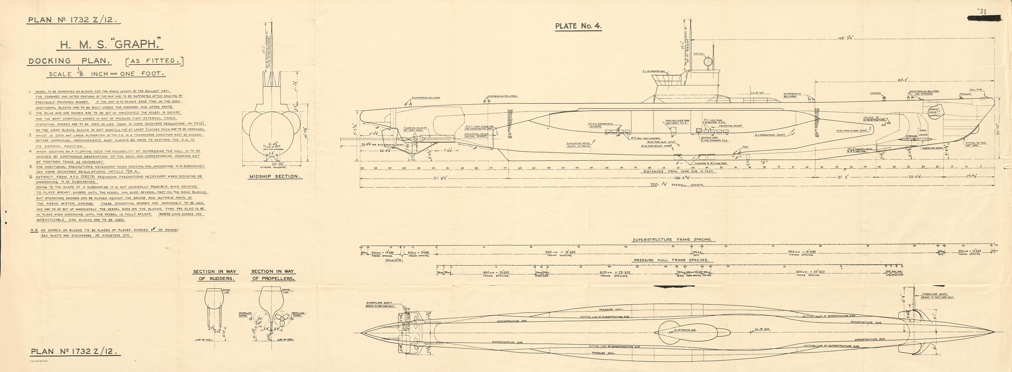
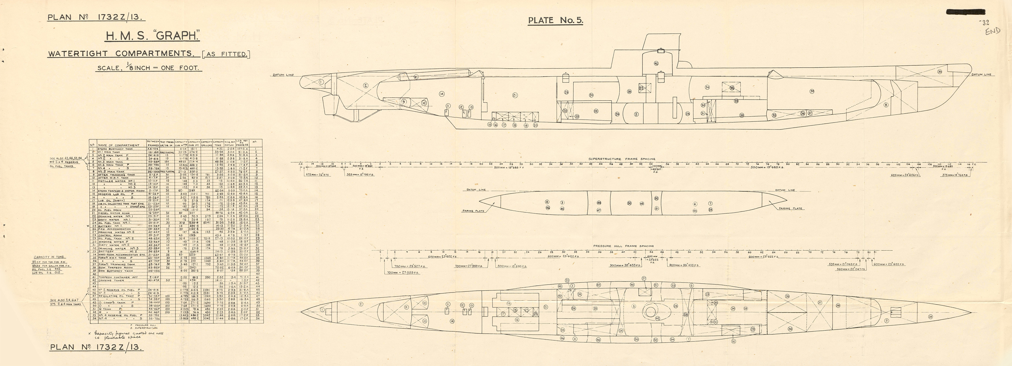
This report and many others are included in the U-Boat Archive Series edited by Jak P. Mallmann Showell. Volume 7 - The Technical Report on U-570, is edited by Terry Andrews and, in addition to the material presented above, contains an intorduction by Jak Showell an index and a Report on Exercises Conducted Against U-570 by the U.S. Navy. The U-Boat Archive series is available from Military Press, an independent publisher specializing in military history and based in the United Kingdom. Volume titles are listed below. |
||||||||||||||||||||
|
||||||||||||||||||||
| Additionally, Bury the Wolves Deep - Operation Deadlight, by Terry Andrews will be available from the publisher in the near future | ||||||||||||||||||||
 |
Click on the logo at left to proceed to the Military Press page on U-boat related books | |||||||||||||||||||