SECTION II - B - 4. . . . . . . . . . . . . . . . . . . . . . FLOODING AND VENTING: |
||
(a) There are three M.B.T.'s fuel-ballast tanks, a stern buoyancy tank and a bow buoyancy tank. (See Section II-B-1 for tank capacities). In this report tanks are numbered from aft forward. The middle main ballast tank is apparently constructed as a safety tank. |
||
(b) FLOOD VALVES are fitted in M.B.T. No. 3 in fuel-ballast tanks. (see Plan No. 28). M.B.T. No. 3 is directly below the C.R. flat and within the strength hull. M.B. Tanks No's 1 and 5 are open to the sea through flood openings in their bottoms. Flood valves are manually operated by tee wrenches or cranks used on the ends of operating gear shafting extending into working spaces of the pressure hull. (Areas of flood valve are shown on Plan No. 28). |
||
(c) VENT VALVES of M.B.T.'s and Fuel-Ballast Tanks are manually operated from the control room. The vents of bow and stern buoyancy tanks are operated manually by hand wheels in the forward and after torpedo rooms respectively. Vent pipes from Fuel-Ballast Tanks No. 2 and No. 4 starboard lead to a common master vent valve abreast and on the conning tower. Vent pipes from Fuel-Ballast Tanks No. 2 and No. 4 port lead to a similar master vent valve on the port side. Vent ducts from M.B.T. No. 3 starboard and port lead from openings in the I.H. into and through the regulating tanks which are adjacent to M.B.T. No. 3. Emergency vent valves are fitted on the lower ends of these ducts at the I.H. These emergency vent valves are operated manually from the control room by tee wrenches. The master vent valves of Fuel-Ballast Tanks No's 2 and 4 and the vent valves of M.B.T. No. 3 are quick opening lever operated valves. Hand operated |
||
- 20 - |
||
emergency vent valves are provided in Fuel-Ballast Tanks No's 2 and 4 port and starboard. The vents of M.B.T's No's 1 and 5 are operated by hand wheels in the C.R. |
|||||||||||||||||||||||||||||||||||||||||
Separate vent pipes lead from the after ends of F.B.T.'s No. 2 Stbd & Port over the inner hull to vents on the middle line. Emergency vent valves are installed in these vent pipes. The vent valves at the top of the inner hull are controlled by a single hand wheel in the control room. (See Plan no. 16). |
|||||||||||||||||||||||||||||||||||||||||
Certain accessible vent valves were measured to obtain data for calculating the ratios of tank volumes to vent valve areas. These data are: |
|||||||||||||||||||||||||||||||||||||||||
|
|||||||||||||||||||||||||||||||||||||||||
(Note: This vent is an outward opening hinged type vent. All others are inward opening. It was closed and the clear opening could not be measured. The overall diameter of the valve was 22" (diameter of clear opening probably about 17").). |
|||||||||||||||||||||||||||||||||||||||||
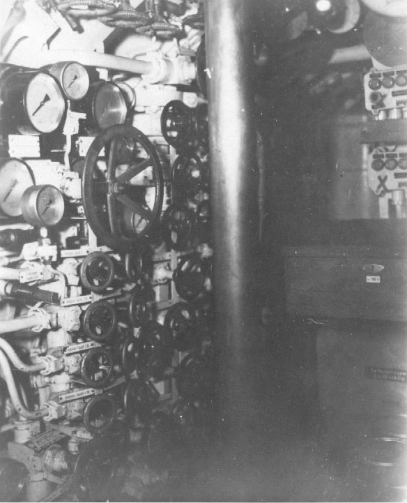
(d) BLOWING: Main ballast tanks and fuel ballast tanks may be blown from the tank blowing manifold in control room. Supply to this blowing manifold from the high pressure flask manifold is manually |
|||||||||||||||||||||||||||||||||||||||||
- 21 - |
|||||||||||||||||||||||||||||||||||||||||
controlled by hand wheel (See Photograph No. 20). |
||
No low pressure blowers are installed. Arrangements are provided for low pressure blowing by engine exhaust gases. A pipe connection to the exhaust system outside of the hull leads forward to a manifold outside of the hull in way of the control room; and exhaust gases may be admitted to ballast tanks by operation of individual external valves from within the control room. (See note under Photograph No. 20). Admission of exhaust gases to this low pressure blowing system is controlled by a valve in the exhaust system outside the inner hull which is operated by a hand wheel in the engine room. |
||
- 22 - |
||