| CONFIDENTIAL | ||
FORMER GERMAN SUBMARINES |
||
INTRODUCTION |
||
Authority |
||
| The design studies, of which this report is a part, have been made under the authority of the Chief of Naval Operations restricted letter Op-23C-1-Serial 217423 of 28 May, 1945. This letter directs the Naval Shipyard, Portsmouth, to prepare design studies, perform tests and to compile reports on each type of submarine. | ||
| Purpose | ||
| This report has been prepared to describe the material components of a single type of vessel. In addition to the purely descriptive matter, the report includes comparison with related U.S. Naval or commercial practices in places where it is believed such comparison is of value in determining the basis of design. | ||
| Where comparisons are made, they are intended to assist in evaluating the particular circumstances, and are not made for the purpose of questioning the existing practice. To the extent that any single item has merit, it has been described, but it is fully recognized that the good points of a single component do not necessarily indicate that an entire system or method is superior. | ||
| Method of Compilation | ||
| This report has been prepared in accordance with the division of subject matters given in the Ship's Material Section of the Navy Filing Manual. All of the "S" groups are represented by text material of by cover pages which either refer to other report sections for related text or indicate the inapplicability of the section. | ||
| In view of the applicability of the Navy Filing Manual as an index for the report no separate index has been prepared. | ||
- 1 - |
||
| Each "S" group in the report on 9C40 vessels is complete within itself and consists of a title page and summary, a description of the appropriate design elements and related remarks and conclusions. The corresponding section in the reports on other types of vessels is not, generally speaking, complete in itself, but describes the changes from the 9C40 vessels which were made when designing the corresponding elements in that one type. This procedure has saved a great amount of duplication, for all the later types were related in varying degrees to the 9C40 and in a number of respects are identical. | ||
| In certain cases, it has been necessary to divide sections into their sub-groups because of the extent or character of the matter described. Generally speaking, however, the subject matter has been briefed by "S" groups without employment of sub-numbering. | ||
| In the case of sound isolation it has been considered preferable to centralize all information in the S-23 group. Sound isolation is applied to components of many different systems and the extent could not be indicated without employing this method. | ||
| Similarly, primary reference to main motors and generators is made in S63, in order to avoid segregating individual aspects of single machines under two "S" groups. | ||
| Reference Material | ||
| At the end of the report is a bibliography which has been cross-listed by the "S" group number. | ||
| The first part of the bibliography is an alphabetical list of the reference material. Each one of the titles is given in German and in English and each title is numbered. The titles are shown in two groups: first, those applicable generally, and second, those applicable to the one type of vessel. | ||
| The second part is a list by "S" groups giving the numbers of the reference titles which were used in the compilation of that section. This is also divided into two groups: first, those applicable to the vessel as a whole, and second, those applicable to parts of the vessel. | ||
| Few of the reports on exploitation of individual components by other agencies, or on operating experience with the vessels, have been received. All reports received as of 22 July, 1946 are listed in the bibliography, but the | ||
- 2 - |
||
| disbanding of the German Submarine Planning group at Portsmouth, as at present constituted, prevents modification of report sections to incorporate material which mat be received at some later date. | ||||||||||||||||||||||||||||||||
| The text and plan material in the bibliography has been used to supplement personal observations by the personnel of the group on board available vessels. | ||||||||||||||||||||||||||||||||
| The vessels on which it was possible to make personal observations are as follows: | ||||||||||||||||||||||||||||||||
|
||||||||||||||||||||||||||||||||
- 3 - |
||||||||||||||||||||||||||||||||
| SHIPS MATERIAL GROUP. | |||||||||||||||||||||||||||||||||||||||||||||||||||||||||||||||||||||||||||||||||||||||||||||||||||||||||||||||||||||||||||||||||||||||||||||||
| As taken From Navy Filing Manual. | |||||||||||||||||||||||||||||||||||||||||||||||||||||||||||||||||||||||||||||||||||||||||||||||||||||||||||||||||||||||||||||||||||||||||||||||
|
|||||||||||||||||||||||||||||||||||||||||||||||||||||||||||||||||||||||||||||||||||||||||||||||||||||||||||||||||||||||||||||||||||||||||||||||
- 1 - |
|||||||||||||||||||||||||||||||||||||||||||||||||||||||||||||||||||||||||||||||||||||||||||||||||||||||||||||||||||||||||||||||||||||||||||||||
| SHIPS MATERIAL GROUP - Continued. | |||||||||||||||||||||||||||||||||||||||||||||||||||||||||||||||||||||||||||||||||||||||||||||||||||||||||||||||||||||||||||||||||||||||||||||||
|
|||||||||||||||||||||||||||||||||||||||||||||||||||||||||||||||||||||||||||||||||||||||||||||||||||||||||||||||||||||||||||||||||||||||||||||||
- 2 - |
|||||||||||||||||||||||||||||||||||||||||||||||||||||||||||||||||||||||||||||||||||||||||||||||||||||||||||||||||||||||||||||||||||||||||||||||
 |
||
|
|||||||||||
FORMER GERMAN SUBMARINE TYPE IX-C |
|||||||||||
DESIGN, MODELS AND PLANS |
|||||||||||
SUMMARY |
|||||||||||
| Vessels are conservatively designed, and as a complete entity present little of interest. Individual details reported in appropriate sections are of interest, however, and are discussed in the appropriate report sections. | |||||||||||
July, 1946 |
|||||||||||
PORTSMOUTH NAVAL SHIPYARD, PORTSMOUTH, N. H. |
|||||||||||
- 1 - |
|||||||||||
|
||||||||||||||||||||||||||||||||||||||||||||||||||||||||||||||||||||||||||
| The principal characteristics of the type 9C40 submarines are given in Naval Technical Mission in Europe Report 312-45, and are summarized below. | ||||||||||||||||||||||||||||||||||||||||||||||||||||||||||||||||||||||||||
|
||||||||||||||||||||||||||||||||||||||||||||||||||||||||||||||||||||||||||
| As it is necessary to qualify the statements made in the report with regard to main propulsion machinery, torpedoes and guns, reference is made to the sections in which these components are discussed. | ||||||||||||||||||||||||||||||||||||||||||||||||||||||||||||||||||||||||||
| The design is conservative, and while individual items of interest have been found, the vessel as a complete entity presents nothing startling, and is generally inferior to contemporary USN design. The letter reports from the Officer-in-Charge, U-858 to the Bureau of Ships, while they | ||||||||||||||||||||||||||||||||||||||||||||||||||||||||||||||||||||||||||
- 2 - |
||||||||||||||||||||||||||||||||||||||||||||||||||||||||||||||||||||||||||
|
||||||||||||||
| do not in all cases confirm findings of other agencies, and do not coincide with German naval experience in all respects, are nevertheless of considerable value in evaluation of the design from an operating standpoint. The letters are listed in the bibliography at the end of the report. | ||||||||||||||
| Information is not available locally with respect to: | ||||||||||||||
| a) Preparation of specifications | ||||||||||||||
| b) Wave formations | ||||||||||||||
| c) Model tests | ||||||||||||||
| d) Detail specifications | ||||||||||||||
| A copy of the general specifications for main and auxiliary machinery is available. A discussion of specifications and instructions will be found in the S1-7 section of the report. | ||||||||||||||
| Changes from design of vessels building are unknown, although reference will be found throughout the report sections to the German equivalent of the Shipalts accomplished after completion of vessels on some or all of the class. The provision of the snorkel, and the changes in armament, with their related structural changes, are examples of this type of change. | ||||||||||||||
- 3 - |
||||||||||||||
|
||||
FORMER GERMAN SUBMARINE TYPE IX-C |
||||
DESIGN OF VESSEL |
||||
SUMMARY |
||||
| The German specifications follow with but few exceptions the pattern of U.S. Naval specifications, and include general specifications for hull, machinery and electrical components, detail hull specifications, special machinery specifications and special electrical specifications. In addition, separate specifications are provided for plans, for instruction manuals, for materials, for methods, and for individual components. Related to these, and considered as specifications by the Germans, are standard plans for other individual components, for example, valves and hull fittings. | ||||
| Much greater use is made of the standards set up by the German counterparts of the several American engineering societies and standards organizations than that made by the U.S. Navy. | ||||
| The general specifications are shorter then the American counterparts, and do not include as much detailed information. | ||||
| The detail and special specifications closely parallel, in content and arrangement, the corresponding USN specifications. | ||||
| Specifications for plans and for instruction manuals are very detailed, and list large numbers of items which must be shown or discussed. Methods specifications, for example, painting specifications, are also very detailed. | ||||
| Materials specifications and standard plans aim at conciseness, and provide a large amount of information in tabular form with a minimum of explanatory text. | ||||
| Specifications and plans are cross-identified to about the same degree as in U.S. naval practice, in which "S" group sections in specifications and plan numbers are the same. Also as in U.S. naval practice, the group numbering carries through to include allowance lists. | ||||
| Comment: When reading the specifications, one is immediately aware of a high degree of pigeon-holing. Everything has | ||||
- 1 - |
||||
9C-S1-7 |
||
| its own place, and is to be found in that place. Unfortunately, not all elements of a specification are so easily classifiable, and the result is that there is a lack of tie-in between the different sections. There will be a section on the hydraulic system, for example, and another on the items operated on the hydraulic system, but there is no reference made to how these components are related. Reference to three or more publications may become necessary before an exact relationship can be established between an operating unit and an operated unit both of which may be on the same bedplate in the ship. | ||
| Specifications for methods, such as the painting specifications, carry about the same amount of detailed information as the corresponding USN specifications, but the normal tendency of separate specifications for parts of the job is to require an excessive amount of detailed compliance. This is particularly true of the specifications for plans and for instruction books. | ||
| The German instruction books were complete and detailed, and were intended to provide a complete description of all parts of the vessel. A set comprised the following separate publications: | ||
| a) A general hull information book | ||
| b) A general machinery and electrical information book | ||
| c) A pictured list of all hull valves and other hull fittings | ||
| d) A list of all points to be lubricated | ||
| e) A separate instruction book on each of the following: main engines; circulating water system; lub oil system; fuel oil system; diesel air and exhaust system; shafting; shaft clutches, gearing and propellers; main motors and generators; main switchboard, main power wiring, main blowers and air conditioning; battery system and battery ventilation; auxiliary switchboards, auxiliary power, wiring and lighting circuits, motors and equipment; cooking and refrigerating; command, announcing and indicator systems; gyro compass; magnetic compass; ballast tank blow, venting and pumping, and WRT system; compressed air system; trim and drain system; hydraulic system; periscope drive (mechanical part); each type of periscope; drying gear; rudder and system (mechanical portion); rudder and plane system (electrical portion - where provided); safety arrangements; periscope depth and extension gauge; fire main; drinking and wash water system; fresh | ||
- 2 - |
||
9C-S1-7 |
||
| water stills; ventilating, air refrigerating and oxygen system; ship's heating; WC arrangements; anchor and windlass; workshop equipment; out-board motor; torpedo handling arrangements. | ||
| Additional separate books are believed to have been provided for the electronic equipment and ordnance arrangements, but with the exception of a few scattered plans and technical books in non-standard format, no such instruction material has been encountered locally. | ||
| One copy of each book was directed to be provided on board, although sets were incomplete on vessels surrendered at Portsmouth. | ||
| Each book followed a standard form, which consisted of: | ||
| a) constructional data, dimensions, materials, ratings, test conditions and list of suppliers | ||
| b) a description of each part of the system | ||
| c) a set of operating instructions for the entire system, with related precautionary notes | ||
| d) instructions for maintenance, including what to do for laying up | ||
| e) instructions for disassembly and reassembly | ||
| f) a description of operating difficulties, usually with a table of symptoms and how to correct them | ||
| g) a statement of possible substitutions on case of a system breakdown, or casualty to any part | ||
| h) a list of on-board spares | ||
| i) a list of reference plans | ||
| j) a group of plates consisting of photographs, diagrams, tables, curves and other material necessary to illustrate the text. | ||
| Although certain of the reference plans were to have been carried on board, no such plans were found on any vessel surrendered at Portsmouth. Further, not all vessels had complete sets of instruction books. | ||
| The amount of information contained varies quite widely from book to book, and from vessel to vessel type. The quality of the information also varies, as some authors seem to have been more concerned with style than with telling a story simply, and others apparently have not all the facts. Further, while the books are bound in such a way as to permit easy substitution of corrected pages, they are in fact a static collection of information, and only rarely have been found to cover all | ||
- 3 - |
||
9C-S1-7 |
||
| system changes. | ||
| The worst set is the one on the type XXI vessels. In an effort to provide as much information as possible certain publications have been released which fail in major particulars to represent the vessels as actually completed. They disagree among themselves on related data, and must be used with discretion. The printed general information book is dated July 1944, but certain systems instruction books were still in draft form in May of 1945. | ||
| Related to the instruction manuals, and used for ready reference in lieu of reduced sized plans, are the sketch books. These are of two types, one of which consists of schematic diagrams of piping systems, including ventilation, and the other of which consists of diagrams showing electric leads, and schematic layouts for the main and auxiliary switchboards. Four copies of each are supposed to be on board each vessel, although this number of copies was rarely found. | ||
| The sketch books provide much ready information. They are of a handier size than the reduced size plans which are the nearest USN equivalent, and provide about the same amount of information as the system diagrams which form a part of the USN plan books. The fact that they can be carried about in a hip pocket greatly increases their value for ready reference. | ||
| Also related to the instruction books are the schematic piping diagrams found at the different system manifolds. These are identical with the diagrams in the instruction books and the sketchbooks, but of larger size. | ||
| Comment: | ||
| Naval Technical Mission in Europe report 304-45 on Training Aids describes the situation leading up to the preparation of the instruction books, and the general method followed in preparing them. Use at Portsmouth confirms their value. | ||
| It must be added, however, that practice departed from principle, and that while the books provide much valuable information, the corrections for the purpose of bringing books up-to-date are all entered in long hand. The only exception to this is in the case of the type X-B machinery sketch book, which has been generally corrected by inserting new pages to bring it up-to-date as of | ||
- 4 - |
||
9C-S1-7 |
||
| the end of 1944. The condition persisted in spite of directives requiring for, correction purposes, reports of changes made and differences encountered. | ||
| The inaccuracies found in the books, as distinguished from the failure to show alterations, are caused by the fact that some books were printed in advance of construction, and could not reflect design changes made after publication date, and by the fact that the war conditions made necessary substitution of other items and other materials for those originally specified. | ||
| The volume of detailed information carried on board is probably less than that carried by USN vessels. The information is, however, in a more accessible form, and (with few exceptions) more portable. The pocket sketch books are notable examples. | ||
- 5 - |
||
|
||||||||||||||||||||
FORMER GERMAN SUBMARINE TYPE IX-C |
||||||||||||||||||||
|
||||||||||||||||||||
SUMMARY |
||||||||||||||||||||
| Information with respect to administration of the shipbuilding, inspections and planning, preparations for building, moulds, launching and docking is available in the reports of the Naval Technical Mission in Europe which cover these phases of the German shipbuilding program. Inasmuch as no local information supplements these reports, this page is inserted for reference. | ||||||||||||||||||||
July, 1946 |
||||||||||||||||||||
PORTSMOUTH NAVAL SHIPYARD, PORTSMOUTH, N. H. |
||||||||||||||||||||
|
|||||
FORMER GERMAN SUBMARINE TYPE IXC |
|||||
TRIALS |
|||||
SUMMARY |
|||||
| Trial requirements are reasonably complete, but available information indicates that trials were made considerably more exhaustive on the type XXI vessels then on earlier types such as the IXC vessels. | |||||
| There is not very much information available as to the method for conducting tests. | |||||
- 1 - |
|||||
9C-S8 |
||
| Trials and tactical data of the German submarines are outlined in trial books prepared for each class. Trials of the ship were segregated from trials of torpedo tubes, guns, and electronic gear. | ||
| Available information consists of two trial books: one for types VII B and C and IX B and C, and one for type XXI. | ||
| The book for the VII and IX types is divided into several sections: | ||
| a) A summary giving the dates on which each of the inspection and test items was conducted. | ||
| b) A description of the preliminary survey items: | ||
| 1. Inspection to determine compliance with specifications, with a list of documents to be presented at the time of inspection. | ||
| 2. Docking inspection. | ||
| 3. General inspection. | ||
| 4. Preliminary surface trials. | ||
| c) Final acceptance. | ||
| 1. Preliminary trim experiment. | ||
| 2. Final trim experiment. | ||
| 3. Surface measured mile runs. | ||
| 4. Submerged measured mile runs. | ||
| 5. Four hour surface run with main motors. | ||
| 6. Fuel oil consumption runs. | ||
| 7. 24-hour endurance runs, and related fuel oil measurement, lub oil measurement. | ||
| 8. Maneuvering on diesel engines, and related | ||
| reversing time | ||
| test of safety devices on sudden release of load. | ||
| 9. Maneuvering on main motors. | ||
| 10. Determination of mechanical losses, in main propulsion systems | ||
| in main propulsion systems, and | ||
| determining lowest main engine rpms. | ||
| 11. Starting engines, and tightness test of exhaust valves, test of hand reversing gear. | ||
| 12. Underway dive without negative tank. | ||
| 13. Underway dive with negative tank. | ||
| 14. Tightness inspection at 30 meters. | ||
| 15. Pressure dock test to 120 meters, with related deflection and bending measurements, inspection of water closets, pressure tanks etc., hand operation of rudder and shafts. | ||
- 1 - |
||
9C-S8 |
||
| 16. Fuel ballast tank leak test. | ||
| 17. H.P. blow test at 12 meters. | ||
| 18. L.P. blow (exhaust gas blow test). | ||
| 19. Flooding time for regulating tanks. | ||
| 20. Flooding time for WRT tanks. | ||
| 21. Blowing time for regulating tanks. | ||
| 22. Blowing time for WRT tanks. | ||
| 23. Trimming time with compressed air. | ||
| 24. Drain system operations from regulating tanks and bilges with main and auxiliary pumps. | ||
| 25. Drain system pump tests against 100 meter discharge head for main pump, and 30 meters for auxiliary pumps. | ||
| 26. Auxiliary trim and drain pump tests. | ||
| 27. Auxiliary trim and drain pump test against a discharge head of 100 meters. | ||
| 28. Trim rating of auxiliary trim and drain pump. | ||
| 29. Unused. | ||
| 30. Rating test of standby C.W. and standby lub oil pump. | ||
| 31. Operation of standby lub oil pump as a fuel oil transfer pump. | ||
| 32. Fine adjustment of regulating tank flooding. | ||
| 33. Submerged suction test of drain and trim pumps from trim tanks. | ||
| 34. Same as 33, but from WRT tanks. | ||
| 35. Power rudder operation. | ||
| 36. Hand rudder operation. | ||
| 37. Power plane operation. | ||
| 38. Hand plane operation. | ||
| 39. Compressor test. | ||
| 40. Distilling plant test. | ||
| 41. Periscope system operation. | ||
| 42. Anchor handling test. | ||
| 43. Towing arrangements test. | ||
| 44. Torpedo and mine handling test. | ||
| 45. Rapid loading of torpedo tube. | ||
| 46. Not used. | ||
| 47. Compartment ventilation. | ||
| 48. Emergency blow test. | ||
| 49. Test of secondary blow connections. | ||
| 50. Emergency compartment air test. | ||
| 51. Air renewing test. | ||
| 52. Test of signal buoy and marker buoy release. | ||
| 53. Report of tests on auxiliary motors under operating conditions. | ||
| 55. Test of control of emergency lamps. | ||
- 2 - |
||
9C-S8 |
||
| d) Signatures of officials certifying the tests. | ||
| e) A group of curves, tables and charts bearing on the following: | ||
| 1. Trimming experiment. | ||
| 2. Surface measured mile data. | ||
| 3. Surface fuel consumption. | ||
| 4. Submerged measured mile data. | ||
| 5. Submerged power requirements. | ||
| 6. Speed-power curve. | ||
| 7. Surface power data. | ||
| 8. 8-hour full power run data. | ||
| 9. Engine maneuvering data. | ||
| 10. Motor maneuvering data. | ||
| 11. Diving data without negative. | ||
| 12. Diving data with negative. | ||
| 13. Ballast tank blowing data. | ||
| 14. Regulating tank flooding data. | ||
| 15. WRT flooding tank. | ||
| 16. Blowing data on regulating tank and WRT. | ||
| 17. Trimming with compressed air. | ||
| 18. Surface and submerged operations, of trim and drain pumps. | ||
| 19. Rudder maneuvering. | ||
| 20. Plane handling. | ||
| 21. Junkers compressor. | ||
| 22. Periscope hoist operation. | ||
| 23. Anchor handling data. | ||
| 24. Towing release mechanism. | ||
| 25. Auxiliary motor data. | ||
| 26. Vibration dampening tests. | ||
| 27. Summary of gun firing tests. | ||
| It will be seen that the detailed information does not cover the entire range of the tests. The remainder of the trials are shown in the book merely as having been carried out on such and such a date. | ||
| Returning momentarily to part (a) above), this part also lists torpedo tube tests, torpedo target arrangements on the periscopes, compass and communications system tests as having been carried out on given dates by other agencies. | ||
| Comment: | ||
| The trial book indicates that the trials are complete, but does not provide much detail as to the manner of conducting the trials. These are apparently to be found in other text material and directives, according to the forward of the trial book. | ||
- 3 - |
||
|
|||||
FORMER GERMAN SUBMARINE TYPE IX C-40 |
|||||
HULL STRUCTURAL |
|||||
SUMMARY |
|||||
| The hull is conservatively designed, and is believed to offer nothing currently constructive. While certain aspects are novel, it is believed that they are heavy and expensive solutions to the particular design problem. | |||||
March, 1946 |
|||||
PORTSMOUTH NAVAL SHIPYARD, PORTSMOUTH, N. H. |
|||||
- 1 - |
|||||
9C-S11 |
||
C O N F I D E N T I A L |
||
HULL STRUCTURAL |
||
| 1. General | ||
| The vessel consists of a cylindrical pressure hull with truncated conical sections at the ends and cast end bulkheads, a conning tower of oval horizontal section with a cast top, a system of exterior ballast and fuel tanks enclosed in a ship-shaped envelope, and a light superstructure with accompanying conning tower fairwater and bridge. A box keel is fitted below the pressure hull. The designer's submergence depth is 100 m. (328'). | ||
| 2. Pressure Hull | ||
| The cylindrical pressure hull has a diameter of 4400 mm (14.42') and is made of 18 mm (.75") steel with inside bulb tee frames 200 x 11 (7.88" web depth x .43" web thickness) on 700 mm (27.56") centers. The plating is gradually reduced throughout the tapered sections fore and aft to 16 mm (.63"), and the frames are correspondingly reduced to 130 x 9 (5.12" x .35"). Frame spacing remains unchanged in the tapered sections. | ||
| The specifications for the pressure hull plating and frames calls for a tensile strength of 74000 psi with a yield point of 51300 psi. The steel is known as No. 52; the specification for plates is KM 9104, and for frames is KM 9103. | ||
| Framing is modified in the way of the main motors, to provide clearance, by substituting double frames 160 x 9 (6.30" x .35") for the normal 200 x 11 frames. | ||
| In addition to the dished end bulkheads of cast steel, four other dished cast bulkheads are fitted, dividing the pressure hull into five pressure compartments. These bulkheads are 22 mm thick; but material specifications, while unknown, are believed to be German cast steel 45.81 per KM 9106. | ||
| Further subdivision is provided by two light fabricated bulkheads, one in the battery compartment forward, and the other separating the maneuvering and engine space in the machinery compartment aft. | ||
- 2 - |
||
9C-S11 |
||
| These are designed for a pressure differential of 3 psi only, but in practice serve no pressure purpose because they have so many non-tight openings. | ||
| Large openings in the pressure hull consist of the two torpedo hatches, one galley hatch, one engine room hatch, and openings in the control room for conning tower hatch and two periscopes. There is also one removable patch in the way of the engine room and another overhead in the battery compartment. | ||
| Compensation for these openings is obtained in a number of different ways: | ||
| (a) For the torpedo hatches, a doubler (in some vessels a single thicker plate) is fitted, increasing the plate thickness from 17 mm normal to 38 mm (1.49"). The frames are cut in the way of the hatches, and are fitted with bearing pieces at the ends, against which strongbacks are wedged and secured in position by toggle pins. | ||
| (b) The galley and engine room hatches have no compensation other than their trunks, which are tubes with 20 mm (.79") walls. | ||
| (c) The overhead openings in the control room are compensated for by increasing the hull plating to 22 mm, by trunking each opening and by fitting angles inside and outside the hull on each trunk. This sounds a little overdone. Further, as the openings make two frames discontinuous, the adjacent through frames are increased to 200 x 15 (7.87" x .59"). | ||
| (d) The patch in the engine room has double butt straps, double riveted, on the plating. Frames are butted, with double butt straps on the webs having 6 rivets on each side. | ||
| (e) The battery patch consists merely of a plate riveted to a frame about 1.5" thick which is welded into the hull plating. | ||
| Within the pressure hull the forward and after trim tanks, and the WRT tanks, are the only structural tanks designed for more than a gravity pressure head. The remaining structural tanks consist of four fuel tanks, the lubricating oil tanks, the fresh water tanks and the sanitary tanks. | ||
- 3 - |
||
9C-S11 |
||
| The conning tower is a relatively small oval cylinder mounted vertically on the pressure hull. Plating thickness is 40 mm (1.18"). Frames are vertical. The structure is closed at the top by an elaborate steel casting incorporating periscope and hatch rings, and ribs extending to the top of the frames. The specified plating material os identified as special Wh n/A, not further identifiable with available reference material. The cover casting is of chrome-molybdenum-vanadium steel. | ||
| The entire pressure hull is welded except for the patches mentioned above. Butt joints are employed on the shell, and where heavier plating adjoins lighter plating, the heavier plating is scarfed to the lighter thickness at the weld. Where the shell is welded to the cast end bulkheads and where the conning tower plating joins the cover casting, however, the outer surfaces are flush, but the inner surfaces are not, and a fillet of weld metal has been built up from the plate to the thickness of the casting. Intermittent welding is used only on the stiffeners for the two light fabricated bulkheads. The cast type of pressure bulkhead is welded to a ring on its periphery, which in turn is welded to the pressure hull. The door frames in these bulkheads are riveted. | ||
| 3. Outer Shell | ||
| The outer shell which includes the end portions of the superstructure, encloses the bow and stern buoyancy tanks, three main ballast tanks, five fuel ballast tanks, one normal fuel oil tank, two variables ("regelzelle" and "regelbunker") and the negative tank. | ||
| Later vessels had four fuel ballast tanks and two normal fuel tanks. Of interest is the fact that one of the three main ballast tanks has flood valves, discussed further under the section on drain and trim systems. | ||
| The outer hull does not extend around below the pressure hull except well forward. In the way of the stern buoyancy tank and MBT 1 it extends across the top of the pressure hull. As a result of these characteristics, only the buoyancy tanks and MBT 1 and 8 are single tanks. All other tanks are twins with interconnection only to the extent permitted, by the piping connections in each case. | ||
| The ballast and fuel tanks are designed for internal pressures not exceeding 9 psi, although the variables and the negative tank withstand greater pressures. | ||
- 4 - |
||
9C-S11 |
||
| Plating is normally run in horizontal strakes of 6 mm (.24") material. In the way of the variable (regelzelle) tanks there are three strakes, the upper and lower of which are 15 mm (.59") while the middle one is 20 mm (.79"). In the way of the negative tank there are two strakes, the upper of which of 15 mm (.59") while the lower, extending in to the pressure hull at the bottom of the tank, is 20 mm (.79"). The heavier plate extending all the way down serves to compensate in part for the flooding openings in the negative tank. Elsewhere in the outer shell, as well, heavy plates are worked in lieu of doublers as partial compensation for openings. Light 5 mm (.20") plating is used on deck at the ends of the vessel. | ||
| Framing is 60 x 6 (2.36" x .24") bulb tees except in the way of the stern buoyancy tank where part of the frames are 75 x 50 x 8 (2.95" x 1.97" x .31") bulb tees, and in the way of MBT 8 and the bow buoyancy tank where part of the frames are 60 x 40 x 5 (2.36" x 1.58" x .20") angles. Frame spacing is 500 mm (19.68") throughout. | ||
| Frames are discontinuous in the way of flood valves and larger flooding openings, and are terminated on longitudinal headers outboard of such openings. The headers are in turn terminated on web frames on bulkheads fore and aft of the openings. Tank plating is normally 12 mm (.47") in the part of the tank where frames are discontinuous. | ||
| Tank bulkheads are 5 mm (.20") bulkheads with light bulb tee 60 x 6 (2.36" x .24") or smaller radial stiffeners. Web frames are similarly constructed, but with fewer stiffeners and many lightening holes. The pressure bulkheads for the variable and negative tanks are 18 mm (.71") and are dished inward, without stiffeners, on earlier vessels of the type, although it appears that stiffened plate bulkheads were used on later vessels. | ||
| Radial bracing of the outer shell frames is accomplished by means of 50 x 50 x 6 (1.97" x 1.97" x .23") angles bracketed to the pressure hull at one end and to the outer shell frames at the other end. Structure consists uniformly of a V assembly bracing the outer edge of the tank top and the upper portion of the frame, a single bracing member at the point of greatest beam and an N assembly which carries the compressive load around the turn of the tanks at the bottom. The lower angle of the N terminates on the longitudinal headers where these are fitted. | ||
- 5 - |
||
9C-S11 |
||
| Except in the way of the variable and negative tanks, the tanks are built with flat tops. Tops of the variable and negative tanks, however, are rounded over and brought in normal to the pressure hull. There are drain pipes through the tanks to drain the waterway formed by the tank margin plate and the pressure hull. | ||
| Welding is employed except between strakes E and F, which are lapped and riveted, for frames at the ends of the vessel, and for propeller shaft fairwaters, which are riveted to the plating. On earlier vessels of the type, the riveting extended the entire length of the vessel, but on vessels actually seen a lap weld was made from outer hull frame 1 to 118 and riveting was retained from outer hull frame 118 and aft of 1 (frames are numbered from the stern post forward). The retained section is double riveted. The section in which welding has superseded riveting was formerly single riveted. | ||
| Outer shell plating is steel 42 (60000 psi tensile) specification KM 9104, except in the way of the variable tanks and negative tanks, which are specified to be of steel 52, (74000 psi tensile) specification KM 9104. Outer shell frames are steel 42 specification KM 9103. | ||
| 4. Superstructure | ||
| The superstructure consists of a light frame structure of angles, with a strake of plating riveted along the sides, and plating sections secured by machine screws on deck in the way of the two capstans and the 10 topside torpedo stowage tanks. The remainder of the deck is of wood slatting. Note here that the two forward torpedo stowage tanks on the starboard side have been removed in those vessels equipped with snorkels. | ||
| The superstructure encloses, as well, the ballast tank vent piping and valves, the induction and exhaust air ducts, the mufflers, work boat and the usual other stowages. It also provides foundations for bitts and fairleads. | ||
| Extending above the superstructure is the conning tower fairwater and bridge structure, projecting from the front of which, at the base, is the non-magnetic (aluminum-manganese 5.25 per specification KM Norm 9304) housing for the magnetic compass. As originally designed, the structure extended aft of the conning tower far enough to provide a housing for the outboard ventilation valves, and provided a bridge platform with room for one 20 mm gun. As redesigned, the structure was widened and raised aft of the bridge proper, to provide space for two 37 mm guns, and was extended aft | ||
- 6 - |
||
9C-S11 |
||
| at a lower level to provide room for a 40 mm gun. Splinter protection was added at the same time. | ||
| The fairwater and bridge bulwark plating is 3 mm (.12") and the bulwark is further provided with 14 mm (.55") splinter protection. Steel 42 (60000 psi tensile) is used for plating and framing except for: | ||
| (a) Splinter protection, which is probably special steel known to the Germans as Wsho/Mo. | ||
| (b) Plating and framing within 900 mm (35.4" of the magnetic compass, which is of aluminum-magnesium 5.25 per specification KM 9304. | ||
| Riveting is employed throughout except for removable plates which are provided with screws. | ||
| The keel section is a box section extending from the bottom of the pressure hull, and faired in to the pressure hull at both ends. It is made up of a central vertical keel of 8 mm (.31") material and a heavy sole piece. Vertical transverse stiffeners from the pressure hull to the sole piece, complete the strength members. The outboard faces of the box are closed by light plating secured with screws, and the space on both sides of the vertical center kiel within the light side plating is used for the stowage of cast iron block ballast. Scantings of the box keel are not available. Material is steel 42. | ||
| Aft of the end of the box keel, and extending aft as far as the rudder, a deadwood is built out below the pressure hull, which provides a housing for the stern planes, struts and rudder skeg. In section it approximates a V. Scantlings are not available. Material is steel 42. | ||
| 5. Internal Decks | ||
| Walking flats are in general very light. Further, no reinforcing is provided below hatches, so there is a permanent dent in the deck below each hatch. Substantial decking is provided only over the battery wells. | ||
| 6. Castings | ||
| There is no stem casting. A casting is employed at the after end of the deadwood and another casting extends below the deadwood to serve as a skeg and, when docking, as a means of supporting the after structure of the vessel. The struts are castings the arms of | ||
- 7 - |
||
9C-S11 |
||
| which are riveted to the pressure hull and to the deadwood. | ||
| 7. Foundations | ||
| Foundations for main machinery are fabricated structures, the inboard elements of which extend the full length of the machinery compartment including the maneuvering room. The outboard elements are not interconnected longitudinally. Vertical members run 12 to 14 mm (.47" to .55") laterally braced at each frame. Sole pieces for the main engine are 24 mm (.94") and for the motors and thrust bearing are 20 mm (.79"). | ||
| Foundations for auxiliaries present nothing of note except for matter which is discussed under sound isolation. | ||
| Foundations for guns are undeserving of comment except to mention that the foundation for the 105 mm deck gun, forward of the conning tower, incorporates a heavy cast ring for the mounting bolts. | ||
| 8. Comments | ||
| The hull structure presents little of interest. The employment of castings for bulkheads and for the top of the conning tower is novel, but is an expensive way to obtain the desired strength. The tremendous masses of weld material employed in welding the castings to the plating are of debatable merit. | ||
| Further, in transferring the basic design to the completed vessel, it appears that weaknesses have been introduced. Compensation for hull openings does not appear adequate in all cases, and is particularly bad in way of the machinery patch, where any load on the frames must be transferred through rivets in shear. The lack of means for adjustment of the strongbacks in the way of the torpedo hatches is also undesirable in this regard. | ||
| The drawbacks to scupper pipes led through tanks are too well known to require comment. It is curious that they should have been retained, as the lightness of tankage plating and framing makes them very susceptible to damage. | ||
| While workmanship was in general good, details were not in all cases satisfactory. Gross pitting of welds of foundations to hull was noted in certain cases, and pipe and cable hangers were apparently located | ||
- 8 - |
||
9C-S11 |
||
| without regard to surroundings, as witness the welding of hangers to rivets, caulked edges of rivets and plates and to foundation bolts. | ||
| 9. Conclusions | ||
| The hull is, as a complete entity, believed to be inferior to contemporary U.S. Naval construction. | ||
| 10. Recommendations | ||
| It is not believed that the hull is deserving of further exploitation. | ||
- 9 - |
||
|
|||||
FORMER GERMAN SUBMARINE TYPE IX C-40 |
|||||
HULL FITTINGS |
|||||
SUMMARY |
|||||
| Hull fittings are not of interest. The increased use of disappearing bitts to reduce resistance will be discussed under the corresponding section of the type 21 report. | |||||
March, 1946 |
|||||
PORTSMOUTH NAVAL SHIPYARD, PORTSMOUTH, N. H. |
|||||
- 1 - |
|||||
9C-S12 |
||||||||||
C O N F I D E N T I A L |
||||||||||
HULL FITTINGS |
||||||||||
| The hull fittings provided consist of the following: | ||||||||||
|
||||||||||
| Special hull fittings consist of: | ||||||||||
|
||||||||||
| In addition, special fittings originally fitted, but removed after completion of the vessel, were cable cutters on the stem and at the forward end of the clearing lines. | ||||||||||
| There is nothing remarkable about the hull fittings, except that the forward bitts can be dropped down to the deck level when not desired, by turning each head until it is free of the locking ring which holds it in a raised position, and lowering into a socket which is fitted in the superstructure. On some ships all bitts were drop type. | ||||||||||
| The bow plane guards are relatively heavy horns which are of streamlined section, and extend out and aft away from the hull in a horizontal plane forward of the bow planes, with the extreme end of the horn outboard of the outer edge of the plane, on the axis of the plane shaft. There is no connection between the outer edge of the plane and the end of the horn. | ||||||||||
- 2 - |
||||||||||
9C-S12 |
||
| The propeller guards, which also serve as stern plane guards, are similar in general character to the bow plane guards, but are carried outboard forward of the rudders, and then straight aft to the turning axis of the stern planes, where they are connected to the planes, thereby permitting the planes to contribute to their support. | ||
| The rudder guards are merely light pieces of plate carried aft from the docking horn under the stern frame, and loosely secured to the bottom of the rudders. | ||
| A single clearing line leads aft from the stem to the top of the bridge bulwark. Twin lines are carried aft, port and starboard, from the outer end of the bridge railing to the towing bitts. | ||
| Fairing of small components extending above the superstructure deck is limited to the stern light. | ||
| Locks and keys are notable for number, but not for security. The vessel was constructed with innumerable small lockers, lazarettes and cupboards, most of which had their own locks with old-fashioned bit keys. Plastic key-holes and door pulls were provided. | ||
| CONCLUSIONS: | ||
| Hull fittings are undeserving of further research. | ||
- 3 - |
||
|
|||||
FORMER GERMAN SUBMARINE TYPE IX C-40 |
|||||
ARMOUR PROTECTION |
|||||
SUMMARY |
|||||
| Armour protection is confined to 14 mm (.55") thick splinter protection on both sides of the bridge, extending from the bridge deck to the top of the bulwark. | |||||
| Material is tentatively identified as Waho/Mo, a special steel. | |||||
| The ballistic properties of the steel, if not already determined from other sources, would be of interest, but the protection is not otherwise unusual. | |||||
March, 1946 |
|||||
PORTSMOUTH NAVAL SHIPYARD, PORTSMOUTH, N. H. |
|||||
- 1 - |
|||||
|
|||||
FORMER GERMAN SUBMARINE TYPE IX C-40 |
|||||
DECK COVERINGS |
|||||
SUMMARY |
|||||
| East Prussian scotch pine (Kiefer) wood decking is employed on the superstructure deck except at the ends of the vessel, and on the bridge. Wooden gratings are provided for installation in the battery and pump room hatches when the metal hatch covers are removed. Further, a web of wooden battens is secured to the deck within the working circle of the machine guns. Within the vessel, wood decking os provided in the magazine. | |||||
| Wood grating is used in the washroom, in the heads, and in the refrigerator. | |||||
| Tile is provided on deck in the galley and the heads. | |||||
| Linoleum deck covering is provided in the living spaces and in the torpedo rooms. Linoleum over wood decking is provided in the sound and radio rooms. Rubber link matting is provided in the maneuvering room, engine rooms and control room | |||||
| Warts of weld metal provide a non-skid surface on the metal portions of the superstructure decking, and in the vicinity of the torpedo tubes. | |||||
| Diamond plates are used only in the engine room. | |||||
| The foregoing list presents nothing unusual, and further research is not indicated. | |||||
March, 1946 |
|||||
PORTSMOUTH NAVAL SHIPYARD, PORTSMOUTH, N. H. |
|||||
|
|||||
FORMER GERMAN SUBMARINE TYPE IX C-40 |
|||||
GASOLINE |
|||||
SUMMARY |
|||||
| No evidence of gasoline stowage or equipment has been found on this type of vessel. The section is, therefore, inserted merely for record. | |||||
March, 1946 |
|||||
PORTSMOUTH NAVAL SHIPYARD, PORTSMOUTH, N. H. |
|||||
|
|||||
FORMER GERMAN SUBMARINE TYPE IX C-40 |
|||||
ACCESS |
|||||
SUMMARY |
|||||
| Access arrangements are generally well thought out, but the physical detail are not unusual, and in certain cases are rather definitely objectionable. No further research is indicated. | |||||
March, 1946 |
|||||
PORTSMOUTH NAVAL SHIPYARD, PORTSMOUTH, N. H. |
|||||
- 1 - |
|||||
9C40-S16 |
||
C O N F I D E N T I A L |
||
ACCESS |
||
| A water-tight door is provided in each of the four pressure bulkheads. The door assembly consists of a cast frame fitted and riveted to the dished bulkhead, and a circular cast door with a square section rubber gasket. The door is secured by means of a rotating geared locking ring on the periphery of the door frame. The ring is provided with lugs which, when the ring is rotated by turning a pinion by means of a crank on either side of the bulkhead, engage wedge surfaces on the door and compress the gasket on a flat seat. The door is further designed to prevent movement of the locking ring when the door is open, and the door hinges are so designed as to give free play when dogging the door. The operation and the mechanism is almost identical with that on the breech door of a USN submarine torpedo tube. The clear opening is 800 mm (31.5") in diameter. Corrosion-resisting material is not employed. | ||
| Hinged doors in the light water-tight bulkheads are provided with 6 dogs and have a clear opening of 1450 x 850 (4'9" x 20.6"). Lower doors are of wood or metal, depending on location, and all have a clear opening of 1450 x 450 (4'4" x 17'7"). | ||
| Pressure hatches are provided as follows: | ||
| After torpedo room (access & torpedo) | ||
| Engine Room (access) | ||
| Conning tower upper and lower (access) | ||
| Galley (access) | ||
| Forward torpedo room (access & torpedo) | ||
| The clear opening diameter of the torpedo hatches is 660 mm (26"). That of the other hatches is 600 mm (23.6"). The dished radius for torpedo hatches if 850 mm (33.4"), for all other hatches except the upper conning tower hatch is 555 mm (21.8"). In this last case the thickness of the hatch cover is increased 50%. | ||
| All hatches are fitted with counter springs, latches, worm drives for three dogs, and dovetail section gaskets. The seats of the hatches on certain vessels examined are | ||
- 2 - |
||
9C40-S16 |
||
| brass strips screwed to the tops of the hatch trunks. | ||
| The principle on which the hatches operate is the same as that in use in the U.S. Navy. The scantlings of the mechanism check closely with those in current use, the gasket is unsatisfactory, and the seat assembly where brass strips are used offers unnecessary possibilities for leaks. | ||
| Rectangular hatches 500 x 500 (19.7" x 19.7") give access from the control room to magazine No. 1, from the walking flat to each battery at two locations, and from the galley to magazine No. 2. These are light portable affairs, fitted flush, with a waterway around the bottom of the opening. | ||
| Manholes are provided to give access to each tankage compartment, pressure tank and interior tank. All are bolted, with a clear opening of 300 x 400 mm (11.8" x 15.7"). Compensating rings are provided in the case of manholes in pressure tanks, and cover material is 18 mm (.71"). Elsewhere the covers run from 5 to 8 mm (.20" x .31"), depending on the working pressure of the individual tank. | ||
| Ladders, all of which are portable, provide access from below to the hatches listed above. Aluminum or brass tubing and bar stock is used in their assembly. Of interest is the fact that the upper end and lower conning tower hatch ladders are directly over one another, that the lower ladder is at an angle of greater than 90°, and that both are provided with hand rails. | ||
| Ladders and grabs topside are provided as necessary, pipe or round bar stock being used as appropriate. Grabs are also provided in tanks, below manholes, wherever necessary. | ||
| The engine room, lower conning tower and galley hatches are fitted with skirts for use as escape hatches. Further, the conning tower is fitted with a plate extending downward from the overhead aft of the hatch, in order to trap a bubble of air. Although means for escape are provided as shown above, there is only one lung charging manifold, which is located in the control room. The conning tower is not arranged for use as an air lock. | ||
| Apparently considerable thought has been given to the matter of access. Hatches and doors are made as large as possible, and are provided, where necessary, with grabs to | ||
- 2 - |
||
9C40-S16 |
||
| facilitate swinging through instead of climbing through. Ladders are arranged to provide easy access, and hand rails, overhead grabs and similar fittings aid in rapid descent both from the bridge to the control room and from the bridge to the deck guns. | ||
| It is regretted that the manholes do not carry through the same thought, for they are at best a tight squeeze for a middle-aged person, and are frequently so located with respect to adjacent machinery that the clear width given above is not fully available. | ||
| The hatch design is less than satisfactory, as the dogging, gasketing and seating are such as to leave their performance under depth charging open to question. | ||
| The pressure-tight door mechanism, employing ordinary steel as it does, is believed to introduce an unnecessary hazard unless great care is taken in its maintenance. Personnel on board, however, have given favorable report of its performance. | ||
| There is nothing novel in the access arrangements provided, and further study is not believed indicated. | ||
- 4 - |
||
|
|||||
FORMER GERMAN SUBMARINE TYPE IX C-40 |
|||||
TOWERS, MASTS, SPARS, CRANES AND DERRICKS |
|||||
SUMMARY |
|||||
| Provisions are made for a portable jack staff, and for portable flagstaffs at the after end of the bridge and at the after end of the superstructure deck. | |||||
| Nothing further in the line of towers, cranes, derricks, masts or spars is provided except for radio and radar gear and torpedo handling gear. | |||||
| The ship presents nothing under this head worthy of comment. | |||||
March, 1946 |
|||||
PORTSMOUTH NAVAL SHIPYARD, PORTSMOUTH, N. H. |
|||||
|
|||||
FORMER GERMAN SUBMARINE TYPE IX C-40 |
|||||
RIGGING AND CANVAS |
|||||
SUMMARY |
|||||
| A single clearing line is provided from the stern to the forward end of the fairwater. A double clearing line leads aft from the after end of the chariot bridge to the stern of the vessel. Originally a cable cutter was fitted at the forward end of the clearing line, but this has been removed some time after completion of the vessel. | |||||
| Awnings and stanchions had originally been contemplated, but neither were on board at the time of surrender. | |||||
| Canvas was not used for bunk bottoms. Instead, spring bottoms were provided. | |||||
| Weather cloths were originally carried around above the bridge bulwark, but were deleted as a wartime measure. | |||||
| There is nothing unusual or remarkable evident under this head, and further exploitation is not recommended. | |||||
March, 1946 |
|||||
PORTSMOUTH NAVAL SHIPYARD, PORTSMOUTH, N. H. |
|||||
|
|||||
FORMER GERMAN SUBMARINE TYPE IX C-40 |
|||||
PERSERVATIVE COATINGS |
|||||
SUMMARY |
|||||
| Protective coatings were generally satisfactory. The surfaces of the ballast tanks were noticeably clean. The only exception to the foregoing was the underbody paint, which did not inhibit marine growths at Portsmouth. | |||||
| The color of the interior paint was darker than that used in the U.S. Navy, and there was much woodwork with bright finish. As a result, much light was absorbed which, with the limited illumination provided, should have been reflected. | |||||
| Galvanizing is normal in extent and character. Corrosion protection for the main engine circulating water system, including waterjackets, is provided as a necessary part of the circulating system. | |||||
| Tankage painting is believed worthy of further review. No report on the samples submitted is, however, available at this time. | |||||
July, 1946 |
|||||
PORTSMOUTH NAVAL SHIPYARD, PORTSMOUTH, N. H. |
|||||
9C-S19 |
||||||||||||||||||
C O N F I D E N T I A L |
||||||||||||||||||
PERSERVATIVE COATINGS |
||||||||||||||||||
| Information with respect to paints used and their application is contained in NavTechMisEu Technical Report No. 482-45 and other documents referenced therein. | ||||||||||||||||||
| Descriptive matter herein will be confined to a discussion of which protective coating were used throughout the vessel. | ||||||||||||||||||
| According to specifications, interior painting is as follows: | ||||||||||||||||||
|
||||||||||||||||||
- 1 - |
||||||||||||||||||
9C-S19 |
||||||||||||||||||||||||||||||||||||||||||||||||||||||||||||||||||
|
||||||||||||||||||||||||||||||||||||||||||||||||||||||||||||||||||
- 2 - |
||||||||||||||||||||||||||||||||||||||||||||||||||||||||||||||||||
9C-S19 |
||||||||||||||||||||||
|
||||||||||||||||||||||
| Individual vessels have differed from the forgoing. Some have aluminum in lieu of bilge paint below the walking flat. All vessels seen have handwheels and levers which are to be opened under "rig for dive" conditions painted red, and wheels and levers which are to be closed on "rig for dive" painted green. Notation of this last only appears on the type XXI hull specifications. | ||||||||||||||||||||||
| In addition to the foregoing, equipment which is shock or sound mounted is identified by rose-red marking. | ||||||||||||||||||||||
| Luminous paint is used extensively, both to make gauge dials visible and to locate certain units in the absence of other light source. The lighting is very effective, and the amount of it had led to informal question on the part of operating personnel as to whether it would interfere with dark adaptation. | ||||||||||||||||||||||
| Before departing from the subject of paints, a word should be added with respect to the color coding of piping systems. The coding is used throughout, and together with the sketch book (which also employs the same coding) permits ready tracing of any desired piping system. | ||||||||||||||||||||||
| Cementing is kept to a minimum. Fresh water tanks are the only ones where Portland cement is used. Elsewhere, in places where water may not be easily vacated, drainage is provided by filling the space with bitumastic in such a way | ||||||||||||||||||||||
- 3 - |
||||||||||||||||||||||
9C-S19 |
||
| as to drain the space. Bitumastic is not used, however, in residual water spaces below flood openings and flood valves in ballast and fuel ballast tanks. | ||
| Cork was not used except as refrigerator insulation. | ||
| Interior paint on all vessels observed was very dirty, as a result of snorkeling operations, and amount of soot varying with the distance from the engine room. The use of ivory in lieu of white accentuated the below-standard illumination of the vessel, while the soot completed the gloomy picture. The extensive use of wood for bulkheads, lockers and trim, which was normally provided with a dull rubbed finish, also accounted for excessive absorption of light. | ||
| Exterior paint departs from that given in the specifications in that all black paint is used on all vessels of the type which have been seen. The specified gray vertical surfaces are not in evidence. | ||
| The underbody paint used does not notably inhibit marine growth at Portsmouth. Each vessel which has been docked has been foul underwater and has required extensive cleaning. | ||
| Tanks have been remarkably clean. Paint samples have been forwarded to the Bureau of Ships for analysis, which has not been received as of the preparation date of this section. | ||
| With the exception of the underbody paint, the paints used have served their purpose. Some of them may be synthetic resin paints, as the word appears in the painting specifications without, however, reference to any particular paint. | ||
| Galvanizing is used extensively, Superstructure plating and frames, topside fittings, shafting and steel fittings in the superstructure, sheet steel, all steel fittings inboard below the walking flat, and all steel pipe is galvanized. | ||
| Protection of interior surfaces of pipes, cooling chambers, surfaces of heat exchangers, and all other surfaces within the vessel exposed to salt water is provided by a corrosion-protective oil. | ||
| This is introduced into the circulating and cooling water system by means of the cooling water hand pump in the engine room, which takes suction from the oil container by way of a hose connection. | ||
- 4 - |
||
9C-S19 |
||
| The oil employed is a mixture of "Korrosionsschutzoel" (corrosion preventative oil) in accordance with specification ZdM17 (See Zusammenstellung der Marine-Schmierstoffe, Ausgabe 1943) (Summary of Naval Oils and Greases). This is an emulsifying oil, viscosity 25 Englert (1900 cSt), specific gravity .950, flash point (Pensky-Martens) 90 degrees C., with water 2.5%. It is to be free of alkali, alkali-earth hydroxides, ammoniac and mechanical impurities, and is to meet certain emulsifying and corrosion protective tests specified in the specifications. | ||
| Corrosion protection for battery wells from spilled electrolyte is provided by means of the so-called lime-milk system (Kalkmilchanlage). This is merely a pipe fitted with a funnel or hose connection at the upper end, and with a perforated section or a bilge strainer at the lower end in each battery well. By pouring milk of lime (slaked lime in water solution) into the upper end, an alkali to neutralize the battery acid is, in older vessels, sprayed onto the wing bulkheads of the battery wells from whence it finds its way to the bottom of the battery well. On newer vessels the solution is delivered directly to the bottom of the battery wells. | ||
| The solution is normally evacuated by way of the drain system. | ||
| Care is taken to avoid electrolysis by avoiding bimetallic contact and by making extensive use of zinc wasters and washers. Many valves are fitted with a blank flanges or with pipe plugs on the inner face of which is a plug or a disc of zinc. Removable piped flanges are found in certain salt water lines, which have zinc doughnuts inside them. | ||
- 5 - |
||
|
||||||||
FORMER GERMAN SUBMARINE TYPE IX C-40 |
||||||||
WINCHES AND CAPSTANS |
||||||||
SUMMARY |
||||||||
| See sections as follows: | ||||||||
|
||||||||
March, 1946 |
||||||||
PORTSMOUTH NAVAL SHIPYARD, PORTSMOUTH, N. H. |
||||||||
|
|||||
FORMER GERMAN SUBMARINE TYPE IX C-40 |
|||||
HYDRAULIC POWER |
|||||
SUMMARY |
|||||
| The hydraulic system is used solely to operate the periscope hoists and rotating gear, and the snorkel raising and lowering mechanism. It is operated at a high pressure, but is not well designed. The entire system is sound mounted. | |||||
| Exploitation does not appear warranted. | |||||
March, 1946 |
|||||
PORTSMOUTH NAVAL SHIPYARD, PORTSMOUTH, N. H. |
|||||
- 1 - |
|||||
9C-S21 |
||
C O N F I D E N T I A L |
||
HYDRAULIC POWER |
||
| The hydraulic system is used solely for periscope and snorkel hoists, and for rotation of the fixed eye-level periscope. | ||
| It consists of three accumulator flasks, one main hydraulic oil pump and one standby, and three hydraulic motors, and one hydraulic ram, together with related piping, tanks and controls. | ||
| The system operates at pressures from 48 to 80 kg/cm2 (682 to 1148 psi). The pump cuts in at the lower pressure and cuts out at the upper pressure. | ||
| The volume of each flask is 200 liters, giving a total volume of 600 liters (21.2 cu. ft.). Inside each flask is a cork float to reduce the area of the air in contact with the oil. Extending up into the flask are an oil supply line with a deflector, an oil discharge line, and in one of the flasks two test lines (one at the 6 liter oil level and one at the 12 liter oil level). A high pressure air connection is fitted to the upper end of each flask, with a reducing valve in the air line to reduce the pressure from 3000 psi to 682 psi. The effective oil capacity of the three flasks is 14300 cu. in. (234 liters). | ||
| The main pump is a worm pump (IMO type) with one drive shaft and two idlers, operated by a motor with an intermittent rating of 25.4 to 39.4 H.P., dependent on the voltage, which can vary from 110 to 170 volts. The pump and motor operate at 1470 to 1820 rpm. | ||
| The standby pump is similar to the main pump, but smaller, and is operated by a motor with an intermittent rating of 14.1 to 17.2 H.P., dependent on voltage. The pump and motor operate at 1800 to 2300 rpm. | ||
| The oil supply tank contains 500 liters (17.6 cu. ft.). | ||
| The system is placed in operation by first raising the pressure in the flasks to 10 kg/cm2 (142.2 psi); then | ||
- 2 - |
||
9C-S21 |
||
| pumping oil into the flasks until the level reaches the lower (6 liter) test line. The pump is then shut down and air is bled into the flasks until the internal pressure is 48 kg/cm2 (682 psi). | ||
| From this point on, normal cycling of the system is controlled by an automatic pressure-operated switch, which starts the pump at 682 psi and stops it at about 84 kg/cm2 (1195 psi). Only one pump at a time can be used, and changing from one to the other requires manual operation of a selector switch. | ||
| The pressure switch is not controlled directly by the pressure on the system, but by the static pressure of the oil in the collecting tank. The basic assumption made in the design is that for a fixed quantity of oil in the system, the amount of oil in the collecting tank will reflect the use being made of the system, and thereby the pressure on the system. As oil is pumped from the tank into the flasks, the oil level will be lowered and the pressure reduced, and the switch is calibrated to open the pump motor circuit when the level is lowered to a point which would correspond to the maximum level (and maximum pressure) in the flasks. As oil is used from the flasks, the level of the oil in the collecting tank (and the related static pressure) increases, and when the oil in the flasks has reached the established minimum, the pressure in the collecting tank has reached the point where the switch should be adjusted to start the pump motor. | ||
| The control system requires very close attention to the oil in the system, as a number of odd conditions can arise if any improper relationship develops between the oil level in the flasks and in the collecting tank. | ||
| Flasks are of steel. Piping is of steel, with copper plated interior surfaces. Pipe connections consist of a collar with a short conical section adjacent to the gasket laying surface, and a loose flange which rotates freely on the collar. The end of the pipe is expanded into the conical section and is cut off flush with the normal gasket face of the collar, and solder is run in at the other end of the collar into the annular space between the outer surface of the pipe and the inner surface of the collar. The two halves of the coupling being made up, a gasket is placed between the two halves, and the bolts on the flange are drawn up to complete the joint. | ||
- 3 - |
||
9C-S21 |
||
| The entire system, including flasks, collecting tank and piping, is sound-mounted on "Schwingmetall" pads. | ||
| COMMENTS: | ||
| The system is quite large and cumbersome for the character of the work required. The cork float does not provide adequate oil-air separation and the system is accordingly subject to disabilities resulting from air entrained in the oil. The indirect control of the system leads to the possibility of a number of different types of malfunctioning of the system. The soldering of copper-plated pipes does not insure proper condition of the plating. The spring loaded bypass valve on the pump is probably affected by wire drawing. | ||
| The pumps themselves are well designed and are thrust compensated. | ||
| The motors are light by USN standards, as they run approximately 23 lbs. per horsepower as compared with our 34 lbs. per horsepower for the same system service. In part, this weight saving has been accomplished by using a motor rating based on intermittent service, but the motors, even so, are no lighter than available American commercial types with continuous ratings the same as the intermittent ratings given above. | ||
| CONCLUSIONS: | ||
| The system operates at higher pressures than those employed in current U.S. submarine practice. While certain details of design are of interest as paralleling current U.S. Naval practice, the system as a whole is not well conceived as a compact, reliable, light entity. | ||
| The type of pipe connection has received favorable comment from pipe manufacturers' representatives who have seen it. Samples have been supplied for test as requested by the Bureau of Ships, but report on the tests is not currently available. | ||
- 4 - |
||
|
|||||
FORMER GERMAN SUBMARINE TYPE IX C-40 |
|||||
STEERING AND DIVING |
|||||
SUMMARY |
|||||
| The steering gear and plane operating gear operates on a traveling screw-fixed nut principle. Pushbutton electric control is provided, and hand-wheels are fitted for emergency and silent-running service. Bow planes are permanently rigged out. Twin steering rudders are provided. | |||||
| Rudders and planes are well located to obtain maximum effect with minimum area. | |||||
| The systems are compact, but are not otherwise unusual in any respects, and do not warrant exploitation. |
|||||
March, 1946 |
|||||
PORTSMOUTH NAVAL SHIPYARD, PORTSMOUTH, N. H. |
|||||
9C-S22 |
||
C O N F I D E N T I A L |
||
STEERING AND DIVING |
||
| GENERAL | ||
| Steering arrangements consist of twin rudders, linkage joining the tiller heads and leading forward into the after torpedo room, a traveling worm steering machine driven by an electric motor, electric steering stations in the control room and conning tower, and an emergency hand steering station in the after torpedo room. Associated therewith are the necessary thrust bearings, limit stops, clutches, wiring and indicators. | ||
| The stern plane system consists of twin planes and related components similar in principle to those of the steering system. All operating stations, however, are in the control room, shafting being led forward from the after torpedo room for the hand operation of the stern planes. | ||
| The bow plane system consists of twin, permanently rigged-out planes, with operating gear similar in principle to that of the steering system and stern planes. Operating mechanism is located in the forward torpedo room, but operating stations are in the control room, and shafting is accordingly led aft from the torpedo room to the control room. | ||
| STEERING SYSTEM | ||
| The rudders are of the balanced streamlined hollow spade type, with the interior space filled with wood. Each has a plane area of 3.111 m2 (33.4 sq. ft.) of which .779 m2 (38.4 sq. ft.) is forward of the stock. They are located 975 mm (38.4") out from the centerline of the vessel, and 225 mm (8.85") in toward the center of the vessel from the center of the propellers. | ||
| The rudders are suspended, the weight and thrust being carried by bearings in the rudder trunk and at the head of the stock. Stops are at 30 degrees port and starboard. | ||
| The stocks are provided with tillers, which are joined by connecting rods to a linkage which translates the athwartships movement to fore and aft movement. Another connecting rod leads forward from the linkage to a crosshead. | ||
- 1 - |
||
9C-S22 |
||
| From the crosshead, the rudder drive shaft leads forward through a stuffing box into the after torpedo room. The inboard end of the shaft is fitted with a double trapezoidal thread of 20 mm pitch on an outside diameter of 88 mm (.79" pitch x 3.47" diameter). The shaft moves forward or aft depending on the direction of rotation of a section of shaft which combines the features of a nut and thrust bearing. | ||
| Forward of this last mentioned fitting is a sound isolation coupling, the worm drive from the electric motor and the hand-operated jaw clutch which connects either the electric or hand steering gear, and at the forward end of the shaft, working through two sets of bevel gears, is the emergency steering wheel and mechanical indicator which are mounted on a column suspended from the overhead and are swung out of the way when not in use. | ||
| The drive motor is rated at 6.2 to 11.8 H.P. depending on voltage, speed and duration of operating period. Weight is 530 lbs. It is shunt wound type equipped for dynamic breaking, and is spray tight. | ||
| The motor control consists of a magnetic controller, the relay circuit of which is wired through to a selector switch in the control room. The selector switch extends the circuit either to the permanently connected control stand in the control room, or to a branch terminal box in the conning tower. From the box in the conning tower the circuit can be extended to the conning tower control station as the bridge control stations by means of three-conductor cable. When the bridge station is used, the cable is led down through the upper conning tower hatch to the conning tower terminal. | ||
| The control system also includes a spray-tight travel limit switch which opens the motor circuit when the rudder gear reaches the end of the established travel. This operates through a reduction gear on the nut, which turns on the threaded portion of the inboard rudder drive shaft. The limit switch operates on a worm and traveling nut principle, with cams which, at the end of the worm travel engage contacts, initiate dynamic breaking and stop the motor. Damping coils extinguish the resulting arc. | ||
| Also connected to the same reduction gear as the limit switch is the electric rudder angle indicator, from which leads connect to repeaters in other parts of the vessel, as described in the section on intercommunications (S65). | ||
- 2 - |
||
9C-S22 |
||
| Electric movement of the rudder is accomplished by depressing the "port" or "starboard" pushbutton at the steering station in use, employing the palm or the heel of the hand. Depressing the button closes the circuit to the magnetic controller, which starts the steering motor. The motor in turn, operating through the reduction gear, rotates the female threaded member on the shaft at the thrust bearing, thereby pulling in or pushing out the shaft connecting with the rudder linkage. When the button is released, it returns to normal under control of a spring, opens the circuit to the magnetic controller, which in turn closes the dynamic breaking circuit and then opens the power circuit, thereby stopping the motor. No follow-up is provided, and the rudder remains at the angle set until the angle is changed by further action at the control stand. Control of steering at the operating stations is facilitated by providing a gyro repeater and a rudder angle indicator repeater at each station (Note that certain of these units are portable, so the number of repeaters does not correspond to the number of steering stations). | ||
| Hand steering is initiated by rigging the hand steering column, attaching the steering wheel which is stowed separately, setting the mechanical angle indicator to correspond to the existing rudder angle, and operating the clutch which disengages the electric drive and engages the handwheel. It is to be noted that the electric rudder angle indicator remains in operation, is that locations in the vessel can be kept informed of the rudder angle. Further, it is possible to carry one of the portable gyro repeaters aft to the torpedo room and there connect it, permitting personnel at the handwheel to follow course without recourse to telephone or loudspeaker system. | ||
| DIVING PLANE SYSTEM | ||
| The stern planes are located directly aft of the propellers in the horizontal plane with the center of the propeller shafts. The plane area of each plane is 2.56 sq.m. (27.4 sq.ft.) of which .82 sq.m. (8.76 sq.ft.) is forward of the stock. They are arranged to work from 30 degrees rise to 30 degrees dive and are normally secured at 2 degrees dive. This is a change from previous practice, promulgated in 1943 to reduce the tendency of surfaced vessels to run under. (See Special Wartime Experience - Part XXIV, page 1). | ||
| The bow planes are located 1500 mm (4.92 ft.) above the bottom of the pressure hull, just forward of the forward end of the pressure hull at frame 126. The plane area | ||
- 3 - |
||
9C-S22 |
||
| of each plane is 2.84 sq. m. (30.3 sq.ft.) of which .94 sq.m. (10.1 sq. ft.) is forward of the stock. They are arranged to work from 25 degrees dive to 25 degrees rise, and are normally secured at 7 degrees rise. This plane positioning also stems from the same directive referred to above. Plans available show a designed 5 degree zero setting. | ||
| The plane operating gear is similar to that described above for the steering gear, although it is of different size. The planes are connected port and starboard to a common stock which is provided with a tiller arm. The crosshead, threaded inboard shaft, and all other components follow the same basic design principles as those employed for the steering control, except for the following. | ||
| a) A low pressure air cylinder, with piping to the control room, is provided to permit operation of the power-to-hand clutch from the control room. | ||
| b) Shafting is led from the end of the power drive to the control room, where the hand operating wheels are located. | ||
| c) In addition to the electric plane angle indicator, a mechanical indicator is connected to the limit switch drive shaft, a plane operating gear. The mechanical indicator dial for each pair of planes is located in the control room, adjacent to the diving station. | ||
| The bow and stern plane motors are both rated at 4.0 to 6.8 horse power, depending on voltage and speed. Weight is 364 lbs. Like the steering rudder motor, they are shunt wound, and arranged for dynamic braking. They are water-tight. | ||
| The motor control is likewise similar to that for the steering rudder, both in the type of manual switching at the diving stations and in the type of magnetic controller. | ||
| The travel limit switches, while similar in interior construction to the one associated with the steering control, are water-tight. The electric plane angle indicator is identical with that used on the steering system. | ||
| Electric movement of the stern planes is accomplished by depressing the "up" or "down" pushbutton at the after diving plane station. The sequence of operations is the same as that described above for the steering system. | ||
- 4 - |
||
9C-S22 |
|||
| The electric operation of the bow planes is controlled from the forward diving plane station. | |||
| Each station had its related electric and mechanical plane angle indicator, and, in addition, depth gauges and trim gauge. | |||
| Hand plane control is initiated by operating the clutch switch which disconnects the electric plane control and connects the shafting to the wheel at the diving station. | |||
| It is of interest here to note that later vessels if the type have a third plane control station in the control room and a manual coupling and chain connection between the bow and stern plane handwheels. These are provided to permit the following type of operation: | |||
|
|||
| COMMENTS | |||
| The systems described are of a type which uses available space to maximum advantage. In addition, wheels have been eliminated for normal use, and are retained solely as an emergency and silent-running means for controlling the rudders and planes. There is, however, nothing basically unusual in the arrangement of the components. For details of the electrical components and the indicator systems, reference should be made to the related sections. | |||
| Rudders and planes appear to be well located to obtain maximum effort with minimum area. The steering rudders are inboard of the propeller centers, thereby allowing the inboard rudder on a turn to cut across the slip stream of the inboard propeller, thereby increasing the effectiveness of the inboard propeller rudder combination on turning. The stern planes are immediately aft of, and in plane with the center of, the propellers. The bow planes are located well down on the vessel, ensuring continual submergence, and are so situated as to minimize pocketing of water flow past them. Being permanently rigged, however, they are susceptible to damage to a greater degree then retractable bow planes. | |||
- 5 - |
|||
9C-S22 |
||
| Further with respect to rudders, the vertical center of area is relatively higher on the vessel than it is in current U.S. Naval practice, thereby reducing the tendency for the vessel to take a list when turning. | ||
- 6 - |
||
|
|||||
FORMER GERMAN SUBMARINE TYPE IX C-40 |
|||||
AUXILIARY MACHINERY - GENERAL |
|||||
SOUND ISOLATION & SHOCK MOUNTING |
|||||
SUMMARY |
|||||
| The detailed information with regard to the design and application of auxiliary machinery is given in the applicable "S" group reports, German practices in sound isolation and shock mounting are all that is treated herein. | |||||
| The extensive use of secondary means of accomplishing these ends on installations in the IXC vessel indicate the German's appreciation of the need for sound isolation and shock resistance. | |||||
| In sharp contrast to USN practice, the Germans depend, in nearly all applications studied, upon the adhesion obtained at the fraying surfaces of the rubber and metal used in the mounts. Locking or jacking features as a backup protection in event of failure of the mount are not employed. | |||||
| Tests on representative mounts indicate that the adhesions between rubber and metal are not as good as those available commercially in U.S. | |||||
| Results of sound tests conducted by USN personnel indicate that German auxiliary installations are generally quieter in operation than comparable USN installations. | |||||
July, 1946 |
|||||
PORTSMOUTH NAVAL SHIPYARD, PORTSMOUTH, N. H. |
|||||
- 1 - |
|||||
9C-S23 |
||||||||||
TABLE OF CONTENTS |
||||||||||
|
||||||||||
| Results of tests on a representative German rubber mount used for sound isolation. | ||||||||||
- 2 - |
||||||||||
9C-S23 |
||
| A. Introduction | ||
| The scope of this report is to indicate the German methods and application of sound isolation and shock mounting employed in this type of vessel and to delineate the major differences between German and USN practices. | ||
| The overall German sound isolation and shock mounting program is excellently treated in detail, both general and technical, in Nav Tech Report No. 251-45 dated August 1945. | ||
| A sound test was conducted by the Base Sound Force, New London, Conn. in Gardner's Bay, Long Island, New York to determine the noise levels in water caused by the various German auxiliary machinery installed in U-858. The results of the test are contained in report form and have been forwarded to the Chief of the Bureau of Ships by the Commanding Officer, Subbase, N.L. ltr, NB7/S68 E Serial E-C23 of 18 June, 1946. | ||
| B. Descriptive | ||
| 1. Sound Isolation | ||
| The German's employed to a large degree a secondary means of sound isolation on practically all auxiliary machinery except the Junkers Air Compressor. The wide-spread application of sound isolation, when taken together with the information contained in Nav Tech Report 251-45 pertaining to German conceptions of sound isolating main propulsion plants, leads on to believe the ultimate goal of the Germans was to attain a relatively quiet vessel even when snorkelling. | ||
| In all cases the German depended on the bond of rubber to metal, usually copper plated steel, for sufficient strength under shock conditions. Built in or external locking or jacking devices are not installed. | ||
| The rubber mounts take various forms to suit different installations much the same as available commercially in U.S. today. However, most mounts were presented to the shipyard in desired cross sections of approximately 2" x 2", 2" x 3", 2" x 4", and 2" x 5", the thickness being 2", in lengths of six feet. These were cut in desired lengths and the metal drilled and tapped to suit the installation by the yard. The lengths varied to suit the size of the auxiliary. | ||
| On the larger installations the application was as follows. Two lengths were installed, on on either side at one end, being arranged parallel to each other fore and | ||
- 3 - |
||
9C-S23 |
||
| aft. A third length, usually the full width of the foundation or in some cases two lengths approximately 12 inches long, was arranged to run athwartships. | ||
| Plate #1 delineates the results of tests made on a representative German mount of the type described above. Of particular interest is the relatively low adhesion strength between the rubber and metal, it being only 262 pounds per square inch. It is understood that commercially, mounts of this type are available with adhesion strengths up to 500 pounds per square inch and that adhesion strengths approximating 1000 pounds per square inch have been attained in USN Laboratories. | ||
| In employing a single type mount to serve for both sound isolation and shock mounting, it is necessary to accept a compromise between the two requirements. The German in using a bonded mount attained better sound isolation and due to the relatively poor adhesion poorer shock protection. USN practice has been to emphasize the shock protection requirements and to accept somewhat poorer sound isolation characteristics in their mounts. | ||
| Nav Tech Report 251-45 contains considerable information with regard to the background used in designing and accepting the mounts employed as well as "future" design considerations. In addition the text of the report is copiously cross referenced with numerous design calculations and diagrams as well as outline pictures of the mounts used. Other means used by the German to obtain sound isolation and shock resistance are enumerated below and in some cases, comparisons with comparable USN installations are drawn: | ||
| (a) Pipe couplings are installed in salt water systems similar to those installed in USN systems, but whose basic difference lies in the following. | ||
| 1) They depend in part upon the bonded rubber for strength. | ||
| 2) Only one coupling is used on either side of the given pump rather then the two required in USN practice. | ||
| 3) Both rubber pieces are of relatively equal size and deflection area which is desirable from a vibration viewpoint. USN couplings are provided with one thick and one thin rubber piece, the latter having no deflection are thus making the unit effective only over half a cycle. | ||
| (b) All hydraulic piping is mounted on bonded rubber | ||
- 4 - |
||
9C-S23 |
||
| mounts which again depend upon adhesion of rubber to metal for shock protection. This is understood to have been done because of inability to develop a satisfactory hydraulic hose connection. Auxiliaries supplied by the system are not sound isolated. | ||
| (c) Rubber ducts of suitable shape and size are inserted between the rubber mounted ventilation supply and exhaust blowers and the related ducts. | ||
| (d) Refrigerant piping is not provided with flexible metal or rubber hose sections of any kind, dependence being placed on several turns of the piping coiled in loops of approximately 12 to 14 inches in diameter. | ||
| (e) Rubber collar type couplings which depend upon the adhesion of rubber to metal are used extensively between motors and auxiliaries, even in such vital installations as the rudder and plane operating gear. Locking devices are not employed. | ||
| (f) Considerable attention has been devoted to torpedo handling gear, the loading rack being mounted on pads of rubber, thru bolts being employed in this case. A noteworthy feature is the chain fall arrangement which provides ecliptically shaped rubber cushions molded at approximately five inch spacing on the chain. These rubber cushions engage in the jaws provided in the drive wheel much the same as anchor chain in a "wildcat". | ||
| (g) Cables to motors and controllers are looped to provide reasonable freedom of motion between the auxiliary and the first strap hanger. Sheet rubber is not employed between the cable and the strap hanger. | ||
| The following practices in equipment design with their attendant effects on noise reduction are enumerated. | ||
| (a) Valve designs show a trend toward avoidance of sharp edges and corners in order to decrease "flow" noise and cavitation. | ||
| (b) While the Nav Tech Report indicates the Germans had considered building up small back pressures in liquid lines to reduce cavitation and venting sounds, no installations of this type have been observed in this class vessel. | ||
- 5 - |
||
9C-S23 |
||
| (c) Roller and ball bearings are used in the majority of auxiliaries, however, information brought back by Nav Tech Miss Europe personnel indicate that the German was aware of the desirability of using sleeve bearings with their attendant improvement in sound isolation. | ||
| (d) German auxiliary motors are very compact, carefully designed to minimize abrupt changes in way of ventilation flow, and, more important, spacing between field pole iron is arranged to provide minimum space between adjacent poles thus in effect increasing the mass of the frame, and thereby minimizing the possibility of vibrational disturbance. Armature slots are kept as narrow as possible. | ||
| (e) Satisfactory grease and oil cup fittings for inboard parts, and greasing manifolds for outboard installations are provided. | ||
| (f) Increase in foundation mass to attenuate vibration has not been considered. | ||
| (g) I.C. transmitter indicator systems are mounted on bonded rubber mounts in compression, tension and shear or sound isolation and shock protection. | ||
| I.C. systems which are provided with audible alarms are also provided with a transfer switch to change to flashing light signals when operating under evasive tactics. | ||
| (h) The shaft R.P.M. transmitter is coupled to the shaft by means of V-belts or in some cases with sprocket chain. In both cases the transmitter shaft is coupled to the pulley shaft thru bonded rubber mounts. | ||
| Careful consideration had been given each installation. Observed practices are reasonably uniform and sound "short circuits" have not been observed. | ||
| As nearly as can be determined the results of any sound tests made by the German's on the installed auxiliary machinery were not distributed in report form to the vessel tested. | ||
| No means of self monitoring noise levels of ships auxiliaries is provided. | ||
- 6 - |
||
9C-S23 |
||
| 2. Shock Mounting | ||
| External shock mounting is provided in nearly all cases as compared to the USN practice of designing hi-shock components. | ||
| The mounts provided for sound isolation of auxiliary machinery also served for shock-mounting. | ||
| Items in the categories indicated below are mounted on bonded rubber mounts in compression tension or shear for shock protection. | ||
| a) Main control cubicles. | ||
| b) Switchboards. | ||
| c) I.C. Systems. | ||
| d) Gauges and gaugeboards. | ||
| e) Electronic equipments. | ||
| Neither felt nor any material such as "Fabreeka" has been observed in use as shock mounting. | ||
| Lighting fixtures are not shock mounted nor have the lamps been designed with high shock features incorporated in USN lamps. | ||
| C. Conclusions | ||
| The German approached the problem of sound isolation and shock mounting more elaborately from the secondary viewpoint than is current in USN Practice. However, USN developments along these lines from the primary viewpoint (redesign of equipments as required) are believed to be in advance of German practices due to the fact that his awareness of these changes had not been incorporated in his equipment. | ||
| In spite of the different emphasis in this approach to the matter of sound isolation, the sound test results on the U-858 indicate that a very quiet vessel had been achieved. | ||
- 7 - |
||
9C-S23 |
|||||||||||||||||||||||||||||||||||||||||||||||
MATERIAL LABORATORY |
|||||||||||||||||||||||||||||||||||||||||||||||
U. S. NAVY YARD |
|||||||||||||||||||||||||||||||||||||||||||||||
PORTSMOUTH, N.H. |
|||||||||||||||||||||||||||||||||||||||||||||||
| TEST NO: ___9033___________________ DATE: _______8 Nov. 1945___________ | |||||||||||||||||||||||||||||||||||||||||||||||
| MATERIAL: ____Rubber Motor Mount____ NO. OF SAMPLES: ____one__________ | |||||||||||||||||||||||||||||||||||||||||||||||
| SOURCE: _____German Submarine_______ AUTHORITY: ___Mr. Galle___________ | |||||||||||||||||||||||||||||||||||||||||||||||
| DIMENSIONS OF RUBBER: 2 inches thick, 2 inches by 4 inches in cross-section. | |||||||||||||||||||||||||||||||||||||||||||||||
| TYPE OF RUBBER: Chemical tests indicated that rubber was Buna S. | |||||||||||||||||||||||||||||||||||||||||||||||
|
|||||||||||||||||||||||||||||||||||||||||||||||
|
|||||||||||||||||||||||||||||||||||||||||||||||
| Above Load - Deflection values were the average of 2 readings taken at machine speed of approx. 0.4 inch per minute after mount had been compressed to 1/4 inch deflection and relaxed 8 times. | |||||||||||||||||||||||||||||||||||||||||||||||
PLATE #1 |
|||||||||||||||||||||||||||||||||||||||||||||||
|
|||||
FORMER GERMAN SUBMARINE TYPE IX C-40 |
|||||
SHIP CONTROL |
|||||
SUMMARY |
|||||
| Ship control does not, in general, present any startling innovations, although certain individual components are of interest. | |||||
| The items of interest are the gyro sextant, the gyro compass, the column type depth gauges, and the periscopes. All but the column type depth gauges are subject of other reports not yet available. | |||||
March, 1946 |
|||||
PORTSMOUTH NAVAL SHIPYARD, PORTSMOUTH, N. H. |
|||||
- 1 - |
|||||
9C-S24 |
||
| General | ||
| Ship control arrangements consist of a chariot bridge at the top of the conning tower fairwater bulwarks of which house retractable radio, radar and RDF masts, a small conning tower, a control room, and a maneuvering room. | ||
| Navigational instruments consist of azimuth circles, barometers, (including barographs), several different types of binoculars including a pressure proof type for the bridge pelorus stand, chronometers, clinometers, ship's clock, gyro compass and repeaters, an optically distant reading magnetic compass, depth gauges, leads and fittings, a pit log, sextants including a gyro sextant, echo sounding equipment, meteorological thermometers and stop watches. | ||
| The ships are fitted with demountable bells, fixed chart board, chart locker, megaphones and a hand fog horn. | ||
| Two periscopes are provided, both operated from and used in the conning tower. One of these is a fixed eye level type. | ||
| Ship Control: | ||
| The only navigational equipment permanently fitted on the bridge is the TBT stand, a pressure-proof rudder angle indicator and a pressure-proof gyro repeater. It is possible to steer from the bridge, however, as the steering station in the conning tower can be moved to the bridge and connected by portable cable down the conning tower hatch to the terminal box in the conning tower. Searchlight and signal lamp cable also has to be extended down through the hatch to the conning tower. There are normally four persons on the bridge when surfaced. | ||
| The ship's horn is operable from the bridge. There is also a voice tube from the bridge to the conning tower and control room. | ||
| The conning tower is a small oval compartment in which is located the two periscope operating stations, the periscope hoists and the turning gear for the fixed eye level periscope, an indicator showing the height of the periscope | ||
- 1 - |
||
9C-S24 |
||
| above the surface of the water, torpedo firing keys and TDC, a steering stand, engine order telegraphs, rudder angle indicator, plane angle indicator, shaft r.p.m. indicator, log repeater and dead reckoning analyzer indicator, gyro compass repeater, depth gauges, fathometer, loud speaker amplifier and microphone, sound powered telephone, voice tubes to multiple locations, diving alarm contact maker, and torpedo fire control panel. | ||
| When surfaced, there are normally three persons in the conning tower. Under battle station conditions, there are four. | ||
| The control room is a compartment amidships within the pressure hull of the vessel. In it are located a steering station, the normal plane control stations, (in certain vessels, an auxiliary plane control station), chart board and locker, engine order telegraphs rudder angle indicator, plane angle indicators, shaft r.p.m. indicator, log and DRAI, gyro compass and repeater, depth gauges including a snorkel extension indicator, clinometer, trim indicator, the screen for observing the optically distant reading magnetic compass, loud speaker amplifier and microphone, sound powered telephones, voice tubes, hull opening indicator panel, compartment clear indicator panel, vent valve indicator panel, a mechanical trim and drain order transmitter, and an alarm contact maker. | ||
| When surfaced, there are five persons in the control room. At battle stations, there are ten. | ||
| The maneuvering room and engine room are in one compartment, separated by a water-tight (not pressure tight) bulkhead. Control is not centralized, for when the vessel is operating on diesels, control is in the engine room, while when operating on main motors, control is in the maneuvering room. | ||
| The engine room is fitted with a control stand for each engine, engine order telegraphs, shaft r.p.m. indicators, rudder angle indicator, a loud speaker, alarm bell and light flasher, and compartment clear contact maker. There are normally four persons in the engine room. At battle stations, there are six. | ||
| The maneuvering room is fitted with a control board for each main motor, engine order telegraphs, shaft r.p.m. indicators, rudder angle indicator, loud speaker and microphone, sound powered telephone, alarm bell, compartment clear contact maker, and salinometer. There are normally two persons in the maneuvering room. At battle | ||
- 2 - |
||
9C-S24 |
||
| stations there are three. | ||
| Certain of the items mentioned in the foregoing are of common types and need not be mentioned further, except to say that they are all of a high quality. Items in this category include barometers and barographs, binoculars, chronometers, clocks, sextants, etc. | ||
| Other items are described in the appropriate "S" group heading and will not be further discussed here. Such items include communications and signal systems components. | ||
| A third group includes some items which have been forwarded to certain agencies for exploitation, on which separate reports will presumably be made although they are not available at the moment of writing. These include the gyro sextant, echo sounding equipment, periscopes & gyro compass. | ||
| The periscope hoisting motor is an IMO hydraulic motor operating through a worm gear to drive a pair of cable drums. The cables lead up to the overhead, across to the sides of the well, and down to an equalizing yoke at the foot of the periscope. | ||
| Associated with the pump is a chain of gears which drive a traveling worm valve which determines the limit of travel. A spring-loaded pilot valve and a spring-loaded, lever-operated control valve complete the assembly. All valves are piston type. | ||
| Operation of the control valve opens ports to the travel limit valve and, if the ports of this valve are open, to the pilot valve, operating the piston and opening ports to admit hydraulic oil to the hydraulic motor. This then rotates the windlass, raising or lowering the periscope as desired. | ||
| The raising and lowering device for both periscopes is similar, except that two control valves and a selector valve are provided for the fixed eye level periscope, which is in the after position, in order to permit the operation to be controlled from either of two locations. | ||
| For the fixed-eye level periscope a pedal-operated control valve is provided, which connects with a periscope | ||
- 3 - |
||
9C-S24 |
||
| turning motor. This is smaller than the hoist motor and is mounted overhead on the periscope casing, where it operates to turn the periscope and the attached observer's seat under control of the pedals or, if desired, a hand wheel. | ||
| Associated with each of the periscope hoists is a gauge which shows the amount of the periscope exposed. It operates on a dual water-column basis in which one column consists of a Papenberg gauge showing the external water pressure calibrated in meters submergence, and the adjacent column shows the position of the periscope head. The height of the water level which shows the top of the periscope is determined by the position of a bellows which is geared to the periscope hoist and is compressed as the periscope is raised, thereby displacing water from the interior of the bellows chamber into the water column. Several variations on this mechanism have been seen, but all operate on the same basic principle. | ||
| The gyro compass is of the Anschuetz bell type, which has been manufactured and installed commercially for many years. For further remarks, see section S62. | ||
| The magnetic compass is a standard compass mounted in a pressure-proof case in the superstructure forward of the conning tower fairwater. Lighting is provided, and an optical train leads through the pressure hull to the steering station in the control room, where the image of the rose and azimuth circle appears on a ground glass screen. | ||
| The log is the familiar pitometer type, but instead of being operated by way of tubing extending into the vessel along a sword arm, it is operated by dynamic pressure obtained at the stem, and static pressure obtained from the sea amidships. Pressure differentials are obtained magnetically and are integrated in terms of the known characteristics of the ship to show speed and miles run. | ||
| Depth gauges are of two types: (a) the normal dial spring manometer type pressure gauge, and (b) the water column. | ||
| One 25-meter (82 ft.) manometer gauge is provided in the control room, and five 200-meter (656-foot) gauges are provided, two in the control room and one each in the conning tower and each torpedo room. | ||
| One residual buoyancy and depth gauge reading up to 18 meters is provided in the control room. It is a Papenberg water column type gauge 1175 mm (46.27") long. | ||
- 4 - |
||
9C-S24 |
||
| operating on a straight compression basis, i.e; the upper end is closed, and the lower end can be opened to sea pressure. The level of water in the gauge is adjustable. Two scales are provided: the left hand scale showing the residual buoyancy in metric tons, and the right hand scale showing the depth in meters measured from the bottom of the keel. | ||
| A similar column type depth gauge is provided, which gives a visual presentation of the amount of snorkel above the surface of the water. This is located next to the one above, at the diving station. | ||
| The clinometers are of the usual bubble type, with the exception of one, which is a plumb bob hung in the forward control room bulkhead door opening, with an indicator scale on the bottom of the door sill. | ||
| The trim angle indicators are of two types. One is dial type on which is shown a small representation of the ship, and a line representing the water plane. When the ship takes an angle, the representation takes the same angle with reference to the water plane. This gauge works on the principle of a pendulum. | ||
| The second type of trim indicator is a very long closed loop of piping, with long axis fore and aft and the short axis vertical. The vertical portion of the loop at its forward end is a water column, and is constructed of two conical tubes for the purpose of modifying the scale, thereby increasing the accuracy with which small angles can be read. | ||
| COMMENT | ||
| The navigational equipment provided is normal and generally of a standard commercial type. The gyro-sextant is unusual, however, and one has been sent to the Naval Observatory for exploitation. A report thereon is not available at the moment of writing. | ||
| The Anschuetz gyro compass is a commercial product, but has not been used in recent years by the U.S. Navy, although hearsay has it that certain vessels were so equipped in 1917-1919. The unit is notably smaller and lighter than the current U.S. Navy standard type, and while its life is probably shorter, this is offset by the fact that spare balls can be carried on board and used to replace improperly working elements. It is thought that troubles | ||
- 5 - |
||
9C-S24 |
||
| experienced by personnel on one vessel in the maintenance of the unit may be in part due to unfamiliarity, as verbal report from other vessels indicated that when the air cooling system had been slightly modified, no further trouble was experienced. | ||
| The periscope hoist mechanism is of interest as showing what can be done with hydraulic power, when applied to an accurately cut gear drive on a rope hoist, to reduce noise. The control, however, is unnecessarily elaborate, and shows a lack of realization of the principles which should govern, i.e; simplicity and ruggedness, as brought out in Navtechmisseu report 305-45 on hydraulic systems. As therein mentioned, the attempt to apply the same type of controls to a hydraulic system of increased scope on the XXI vessels was a failure, and resulted in a change. The earlier vessels, however, all have the control valve, pilot valve and operating valve on the periscope hoist, although the control of the periscope turning motor is direct. | ||
| The depth gauges are not generally remarkable. The combination gauge for showing the amount of periscope extended and amount of submergence does provide a direct reading for each, and a comparative reading at the same time, on a relatively large scale. The corresponding water column depth gauge in the control room permits increased accuracy in gauging depth within submergences which allow of periscope observations. | ||
| The column type trim indicator permits accurate trimming and early observation of any tendency of the vessel to change angle under control of the planes. Its character, however, is such as to introduce a large inertia factor which would make it unreliable except for operations not involving intentional change in angle. | ||
- 6 - |
||
|
|||||
FORMER GERMAN SUBMARINE TYPE IX C-40 |
|||||
TOWING |
|||||
SUMMARY |
|||||
| For towing fittings, see S12. | |||||
March, 1946 |
|||||
PORTSMOUTH NAVAL SHIPYARD, PORTSMOUTH, N. H. |
|||||
|
|||||
FORMER GERMAN SUBMARINE TYPE IX C-40 |
|||||
MOORING |
|||||
SUMMARY |
|||||
| Mooring machinery is not of particular interest, and not deserving of further exploitation. It has limited capacity and is slow in operation. | |||||
March, 1946 |
|||||
PORTSMOUTH NAVAL SHIPYARD, PORTSMOUTH, N. H. |
|||||
9C-S26 |
||
| Mooring machinery consists of an anchor windlass forward which can also be used as a deck capstan, and a capstan aft. Only the forward unit is power operated. | ||
| One stockless anchor is provided, stowed flush with the shank in a hawse pipe on the starboard side, and fitted with chain which is stowed in a chain locker. | ||
| Manila mooring lines are provided, stowed in lockers in the superstructure. | ||
| Capstan bars are provided for hand operating of the two capstan heads. A chain stopper is provided, and a chain tripping arrangement is installed in the chain locker. No other accessories are provided. | ||
| Forward End: | ||
| The forward windlass motor is operated by compressed air. It weighs 330 kg (727 lbs.) and is rated at 19 PS (18.7 HP). Air pressure range is 3.5 to 6 atmospheres (50 to 85 psi). It works through a worm drive and clutch which weighs 230 kg (507 lbs.) and which gives a 23 to 1 reduction. | ||
| The capstan head is 180 mm (7.08") in diameter and weighs 52 kg (115 lbs.). It turns at 32.2 r.p.m. when power operated, and is good for 2000 kg (4410 lbs.) load. | ||
| The anchor wildcat assembly weighs 470 kg (1036 lbs.). It operated at 9.6 r.p.m. on a overall reduction of 78 to 1 from the air motor. It is rated for a load of 3700 kg (8150 lbs.) at a chain speed of 11.45 meters per minute (37.6 f.p.m.). The windlass is operated from on deck or from the forward torpedo room. All the gear is located within the superstructure. | ||
| The anchor is a Hall stockless type weighing 500 kg (1100 lbs.). | ||
| The anchor chain provided is 150 metres (82.2 fathoms) of 24 mm (.94 in.) chain, weighing about 1980 kg (4360 lbs.). | ||
| The chain stopper is a worm operated type with jaws which fit the shape of the links. It is operated either | ||
- 2 - |
||
9C-S26 |
||
| from within the superstructure or the forward torpedo room. | ||
| The cable-tripping device consists of a hook and securing pin located in the chain locker, with operating linkage extending through into the forward torpedo room. The bitter end of the anchor chain is secured to the hook, and can be released if the securing pin is raised by operating the handwheel in the torpedo room. | ||
| After End: | ||
| The after capstan is a hand-operated unit with a head 180 mm (7.08 in.) in diameter. It is designed for a maximum head of 800 kg (1764 lbs.) with four capstan bars in use. The weight is 70 kg. (154 lbs.). | ||
| Mooring Lines: | ||
| Comment: | ||
| The low power, low speeds, and the lightness of the anchor are of interest as indicating the probable limiting conditions for mooring and securing. The use of the air motor conserves no weight and space as compared with an electric motor of the same power, and has been found to introduce an additional possible source of casualty. The motor operates from the high pressure air system through a pressure reducing valve. In one instance, as a result of malfunctioning of the reducing valve, the motor has blown up. | ||
- 3 - |
||
|
|||||
FORMER GERMAN SUBMARINE TYPE IX C-40 |
|||||
CARGO HANDLING |
|||||
SUMMARY |
|||||
| This section is inapplicable, and is inserted merely for record. | |||||
March, 1946 |
|||||
PORTSMOUTH NAVAL SHIPYARD, PORTSMOUTH, N. H. |
|||||
|
|||||
FORMER GERMAN SUBMARINE TYPE IX C-40 |
|||||
DESIGNATING |
|||||
SUMMARY |
|||||
| Marking, labeling and designating were the result of considerable thought; and were conceived of as a basic principle applicable not only on board, but as well to sketches, manuals, stowage lists and all other related matter. | |||||
| Circuit designation was simple and clear, and permitted use of smaller fuse and distribution boxes that would have been required if U.S. Naval designation had been employed. | |||||
| The good features of the marking and labeling are deserving of consideration, although it must be acknowledged recommendation as to the adoption of the principle involved is beyond the scope of this report. | |||||
March, 1946 |
|||||
PORTSMOUTH NAVAL SHIPYARD, PORTSMOUTH, N. H. |
|||||
- 1 - |
|||||
9C-S28 |
||
| General | ||
| Designating is in certain cases carried to greater lengths than is U.S. Naval practice, and in other cases is not as complete. | ||
| Class and Type | ||
| All German vessels were designated by class and type. Submarines were designated by "U" (for "Unterseeboot", which is the German for "submarine") followed by a number. The number gave no evidence of type, however. | ||
| Type numbers were associated with plans, instruction books and all other matter related to a given design. For a complete list of types and related "U" numbers, see Naval Technical Mission in Europe Report No. 312-45 on submarine design. | ||
| "W" numbers were also assigned by builders, and will be found referred to on plans and in text material. These numbers are builders' hull numbers, and refer neither to class nor type of vessel. | ||
| Marking Circuits | ||
| Circuits and piping are both identified, though not in a manner directly comparable with U.S. Naval practice. | ||
| Circuit marking follows the principles given below. It is not self-evident, and requires use of the electric systems sketch book to trace circuits. | ||
| a) Each unit is a given number, which appears on the unit, and in the table of connections for the fuse box serving the unit. | ||
| b) If the name or the number of a unit is known, it is possible to refer to the tables in the sketch book and find from which box the unit is served. | ||
| c) Having found the number of the box, the earnest seeker now goes to the box, on which is found an engraved plate with the circuit description code, the unit number in parentheses, and another number, or a word in that order, for each unit. When the box is opened, the figure or word following the unit number on the cover is found painted between | ||
- 2 - |
||
9C-S28 |
||||||||||||||||||
| the fuses of the circuit serving that unit. | ||||||||||||||||||
| d) To follow the circuit further, reference is again made to the sketch book, where it is found that the particular fuse box is served from a particular board in a designated compartment. When traced back to the board, a set of fuses is found which bears the number of the particular fuse box. | ||||||||||||||||||
| e) Any desired circuit can be traced back to the power source, or from the power source to the unit, in the manner described above. The sketch book provides, in each case, a record of the cable size and type, and of the circuit fuse size. | ||||||||||||||||||
| f) All references to circuits in text material on the different systems relate directly to the identification described above. | ||||||||||||||||||
| Other Units | ||||||||||||||||||
| Other marking is detailed in Submarine Painting Specifications (Austrichvorschrift für U-Boote) and in Color Codes for piping, bunkers, cells, tanks and pumps (Farbige Kennzeichung der Rohrleitungen, Bunker, Zellen, Tanks, Pumpen USW). | ||||||||||||||||||
| The system employs principle colors for basic identification purposes, with banding in other colors to provide detailed identification. The secondary banding provided bears a general relationship to the basis code. Colors are as follows. | ||||||||||||||||||
|
||||||||||||||||||
| Examples of combination are as follows: | ||||||||||||||||||
|
||||||||||||||||||
- 3 - |
||||||||||||||||||
9C-S28 |
||||||||||
|
||||||||||
| On board the vessel, piping is marked in accordance with the established code, at intervals of not less than one meter (3.28 ft.). Each mark is at least 150 mm (5.9") long, and where second color banding is provided, banding consists of one section of basic color 60 mm (2.36") long at each end, with intermediate bands as necessary, each of which is 30 mm (1.68") long. | ||||||||||
| Valves are marked with the same color code as the piping. Where a valves separates two piping systems, is is marked with both codes. Extension rods and shafts not fitted with handwheels are also color painted. | ||||||||||
| Direction of flow in air ducts is indicated by arrows: red for supply, blue for exhaust, green for air conditioning and lavender for ozone in refrigerators. A block across the arrow shaft indicates an emergency line. | ||||||||||
| The specified color codes are used not only on board ship, but as well on sketch book pages and in instruction books. Further, the coding in instruction and sketch books is extended to include color identification of the different tanks, containers and of certain compartments, and of the different pumps. | ||||||||||
| Additional Types of Identification | ||||||||||
| Further identification is provided at handwheels on valves. Wheels for hull closures all have a large ball cast on the rim. Valves for seawater lines are balanced cranks with straight handles. For fuel oil, balanced cranks with tapered handles are provided. Lub oil handles are five-sided. Fresh water and hydraulic system valves are five-clover type. Compressed air system valves are circular, with the rim slightly raised above the hub, with three spokes, and with an oval rim section. The exhaust gas blow system valves also have three spokes, but the rim is greatly offset from the hub, and the rim is a flat oval. Emergency vent valves have three spokes, a U-section rim and a hand grip. Hand gear for vent valves has similar wheels with five spokes. The main H.P. blow valve handwheel is a large flat wheel with five spokes. The main H.P. blow valve handwheel is a large flat wheel with five spokes, and the main L.P. blow valve is similar, with three spokes. | ||||||||||
- 4 - |
||||||||||
9C-S28 |
||
| Positions of cocks are indicated by grooves on the end of the square stern head. | ||
| An engraved plate is provided for each unit of any consequence, giving its name or number. All valves, hull fittings, containers, lockers, fuse boxes, controllers, switches etc. are so marked. Practically everything on board has its own label, and all tables interlock with sketch books, instruction manuals and stowage lists, as appropriate. All keys have tags identifying their purpose. | ||
| Distinguishing Marks | ||
| Distinguishing marks are confined to those apparent from the design, i.e: the characteristic shape of the bridge and fairwater, the shape of the stern, and the cutaway superstructure forward. On later vessels, superstructure and fairwater shapes have been changed, but remain such as to be easily identifiable. | ||
| Numerals were not in evidence during the war, but were at other times painted on both sides of the fairwater. | ||
| No historical data plates have been found, and no reference to such plates has been discovered. | ||
| Draft Marks | ||
| Draft marks are provided, but the locations are not identical on all vessels, as some vessels have no forward draft marks, but marks approximately amidships in lieu thereof. | ||
| Draft marks are measured up from the bottom of the keel. Single numbers are painted each decimeter, and thence is a single horizontal line at each odd "0" and a double line right and left of each even "0". Numbers and meter marks are either screwed or welded to the structure. | ||
| Comments | ||
| Marking, labeling and identification are complete, and of such character as to greatly simplify the work of learning the boat. Attention is invited to the extent to which touch identification has been carried. | ||
| Electrical circuit identification, once the principle is recognized, is simple and effective, and has one advantage over the current USN practice, i.e: the elimination of | ||
- 5 - |
||
9C-S28 |
||
| large labels in fuse and distribution boxes eliminates the labels as determining factors in the size of such boxes, and permits a notable reduction in box size and weight. Further, the interrelationship existing between instruction books, sketch books and circuit designation is such that only one text reference is necessary instead of the multiple references required in U.S. Naval practice. | ||
| The use of color codes on piping only where such piping is visible simplifies the painters' work, in that all piping can be painted the same color as adjacent surfaces, and special coloring can be confined to parts of the piping where it is of value. | ||
- 6 - |
||
|
|||||
FORMER GERMAN SUBMARINE TYPE IX C-40 |
|||||
WEIGHT, STABILITY AND INTEGRITY |
|||||
SUMMARY |
|||||
| This type of vessel has adequate stability, but limited reserve buoyancy. Buoyancy is apparently more concentrated amidship than might be considered desirable. | |||||
| Trim and list control is flexible, but apparently has to be augmented at times by movement of personnel to one end or the other of the vessel. | |||||
| Workmanship is in general good, and specified tests are complete and thorough. | |||||
March, 1946 |
|||||
PORTSMOUTH NAVAL SHIPYARD, PORTSMOUTH, N. H. |
|||||
- 1 - |
|||||
9C-S29 |
||
| GENERAL | ||
| The vessel was designed with external main ballast tanks, fuel ballast tanks and fuel oil tanks, bow and stern buoyancy tanks, regulating and negative tanks; internal trim tanks, WRT tanks, and fuel oil tanks. | ||
| A compensation curve is not available. A trim table from U-805 is, however, at hand. | ||
| Damage control was the subject of a considerable volume of text material, but very little information appears to have been provided onboard with regard to drafts, load condition, metacentric heights, and weights. Further discussion on damage control will be found under S88. | ||
| Draft and trim, free-board, immersion and water-lines were subject of some discussion, but available local information is not in all cases complete. | ||
| Stabilizing devices were not provided. The ballast keel probably acted to a certain degree as an anti-rolling device, but there is no evidence that the type of construction was employed for that purpose. | ||
| Evidence with regard to rolling and pitching is secondary, but will be discussed in the detail permitted by available material. | ||
| Workmanship was in general good, but additional comment on brazing and welding will be found herein. | ||
| Strength information is incomplete, but will be covered to the extent possible. | ||
| Tightness tests were extensive and appropriate to the type of construction employed. | ||
| No information is locally available on hogging and sagging, although the design is such that these occurrences could have presented problems in shaft and tube alignment. | ||
| Riveting and bolting were both employed where appropriate, with few exceptions, and will be discussed herein. | ||
| Tonnage data is incomplete, and will not be discussed. | ||
| Weight Displacement and Stability | ||
| Specification weights on the vessel are as follows: | ||
- 2 - |
||
9C-S29 |
||||||||||||||||||||||||||||||||||||||||||||||||||||||||||||||||||||||||||||||||||||||||||||||||||||||||||||||||||||||||||||||||||||||||||||
|
||||||||||||||||||||||||||||||||||||||||||||||||||||||||||||||||||||||||||||||||||||||||||||||||||||||||||||||||||||||||||||||||||||||||||||
- 3 - |
||||||||||||||||||||||||||||||||||||||||||||||||||||||||||||||||||||||||||||||||||||||||||||||||||||||||||||||||||||||||||||||||||||||||||||
9C-S29 |
|||||||||||||||||||||||||||||||||||||||||||||||||||||||||||||||||||||||||||||||||||||||||||||||||||||||||||||||||||||||||||||||||||
|
|||||||||||||||||||||||||||||||||||||||||||||||||||||||||||||||||||||||||||||||||||||||||||||||||||||||||||||||||||||||||||||||||||
- 4 - |
|||||||||||||||||||||||||||||||||||||||||||||||||||||||||||||||||||||||||||||||||||||||||||||||||||||||||||||||||||||||||||||||||||
9C-S29 |
||||||||||||||||||||||||||||||||||||||||||||||||||||||||||||||||||||||||||||||||
|
||||||||||||||||||||||||||||||||||||||||||||||||||||||||||||||||||||||||||||||||
| Ballast, for a vessel with a snorkel, 37 mm guns and other late 1944 alterations, amounted to 91021 kg (200500 lbs.) all of which was carried in the ballast keel. | ||||||||||||||||||||||||||||||||||||||||||||||||||||||||||||||||||||||||||||||||
| Ordnance weights are not available. | ||||||||||||||||||||||||||||||||||||||||||||||||||||||||||||||||||||||||||||||||
| Displacement figures are not complete. Naval Technical Mission in Europe report No. 312-45 on submarine design gives the following figures, which have been substantiated by the available figures on tank capacities, compartment sizes and volume equivalents for known weights: | ||||||||||||||||||||||||||||||||||||||||||||||||||||||||||||||||||||||||||||||||
|
||||||||||||||||||||||||||||||||||||||||||||||||||||||||||||||||||||||||||||||||
- 5 - |
||||||||||||||||||||||||||||||||||||||||||||||||||||||||||||||||||||||||||||||||
9C-S29 |
||
| The center of submerged displacement, according to available trim table, is 29.60 meters forward of pressure frame "0" and 38.80 meters forward of the stern of the vessel. This is further identified on the ballast diagram as 200 mm forward of pressure frame 42, which is just aft of the center of the conning tower. | ||
| Information with regard to surface and submerged GM is not locally available for this class of vessel, nor is the vertical position of the center of buoyancy known. If desired, the vertical positions for surface conditions could be computed from the available body plan, "Bauspantenriss und Plattengänge d. Aussenschiffes", No. S I 11005-5006. (Note: the number given is the one applying to all body plans, and the applicable vessel hull numbers must also be known in order to select the correct plan). | ||
| Complete data on tank volumes and moments is available on the trim table for U-805, prepared by Deschimag, and in the Machinery & Electric Information Book (M und E Kunde) for this class. | ||
| For trim control, trim tanks and WRT tanks are provided. | ||
| Forward trim tanks have a capacity of 5.160 cu. meters, and have a forward moment of 21.06 meters. After trim tanks have a capacity of 5.040 cu. meters, and an after moment of 23.25 meters. They are intended solely for trimming purposes, with a fixed quantity of water which can be pumped or blown as desired from one end of the vessel to the other. An "all empty" or "all full" condition is not contemplated. | ||
| The two WRT tanks forward have a capacity of 6.600 cu. meters and 6.500 cu meters, total 13.100 cu. meters, forward moment of 18.50 meters. The two after WRT tanks each have a capacity of 3.080 cu. meters and a after moment of 20.72 meters. Related thereto, the capacity of each tube is 1.740 cu. meters without piston, and 1.680 cu. meters with piston. Moment for the four forward tubes of 28.90 meters, and for the two after tubes is 30.44 meters. The WRT tanks are also designed for use as wash water tanks at the start of the voyage. | ||
| Buoyancy, ballast, fuel and regulating tanks are arranged as follows: | ||
- 6 - |
||
9C-S29 |
||||||||||||||||||||||||||||||||||||||||||||||||||||||||||||||||||||||||||||||||||||||||||||||||||||||||||||||||||||||||||||||||||
|
||||||||||||||||||||||||||||||||||||||||||||||||||||||||||||||||||||||||||||||||||||||||||||||||||||||||||||||||||||||||||||||||||
| * The port halves of these tanks are vented by one valve, and the starboard halves by another valve. For the four half-tanks there are only two valves. | ||||||||||||||||||||||||||||||||||||||||||||||||||||||||||||||||||||||||||||||||||||||||||||||||||||||||||||||||||||||||||||||||||
| ** Includes auxiliary vent line to forward end of tank. | ||||||||||||||||||||||||||||||||||||||||||||||||||||||||||||||||||||||||||||||||||||||||||||||||||||||||||||||||||||||||||||||||||
| All hand operating gear is located in the compartment nearest the tank concerned. When vent valves are operated in power from the low pressure air system, those for MBT 1 and FBT 3 are controlled by one air valve; those for FBT 4 and MBT 5 by a second air valve; and those for FBT 6 and 7 and MBT 8 by a third. | ||||||||||||||||||||||||||||||||||||||||||||||||||||||||||||||||||||||||||||||||||||||||||||||||||||||||||||||||||||||||||||||||||
| High pressure blow lines are fitted to all tanks except the normal fuel oil tanks. | ||||||||||||||||||||||||||||||||||||||||||||||||||||||||||||||||||||||||||||||||||||||||||||||||||||||||||||||||||||||||||||||||||
| Low pressure (exhaust gas) blow lines are fitted to the main ballast and fuel ballast tanks. Separate cut-offs are provided at the blow manifold to prevent blowing fuel ballast tanks when carrying oil therein. | ||||||||||||||||||||||||||||||||||||||||||||||||||||||||||||||||||||||||||||||||||||||||||||||||||||||||||||||||||||||||||||||||||
| Gate valves are fitted in the vent lines of the fuel ballast tanks between the vent valves and emergency vent valves. Those for FBT 4, 6 and 7 can be operated from within the vessel. | ||||||||||||||||||||||||||||||||||||||||||||||||||||||||||||||||||||||||||||||||||||||||||||||||||||||||||||||||||||||||||||||||||
- 7 - |
||||||||||||||||||||||||||||||||||||||||||||||||||||||||||||||||||||||||||||||||||||||||||||||||||||||||||||||||||||||||||||||||||
9C-S29 |
||
| In addition to the foregoing tanks, the vessel is fitted with two internal fuel oil bunkers, and with collecting and gravity service tanks, fresh water tanks, battery water tanks, wash water tanks, sanitary tanks, and lub oil tanks, each of which is discussed under its appropriate system. | ||
| The total fuel oil which can be carried, with all suitable tanks filled, is 24,9044 liters. | ||
| The total lub oil which can be carried is 12550 liters. | ||
| Total battery water is 505 liters, drinking water is 4070 liters, and wash water (including use of WRT tanks) is 19320 liters. | ||
| Sanitary tank capacity is 1140 liters. | ||
| No safety tank is provided. | ||
| Service conditions encountered, and used basically by the Germans in all calculations, are condition A (Zustand A), in which fuel ballast tanks carry water, and condition B (Zustand B), in which they are filled with fuel oil. The latter is the normal condition. | ||
| Further, according to the machinery and electrical information book for this class (M und E Kunde), ballast tanks 1, 5 and 8 are intended to give the vessel the necessary surface buoyancy; ballast tank 5 serves also as receptacle for oily bilge water pumped out of the vessel while submerged; the buoyancy tanks provide additional buoyancy and the bow buoyancy tank is a safeguard against running under in a seaway; the regulating tanks serve to compensate for use of oil, supplies and munitions and for the difference in specific gravity of water, and the regulating bunker can be employed as a fuel oil tank; the trim tanks provide compensation for longitudinal changes in the center of gravity of the vessel; the WRT tanks take the water from the torpedo tubes and compensate for the weight and moment of the torpedoes, and in addition provide a means for compensating for weights and trimming moments which cannot be compensated for by the trim and regulating tanks. | ||
| The negative tanks are, under war conditions, carried half full, are completely flooded to accelerate a dive, and are blown at a depth of 9 to 11 meters, which is qualified by "depending upon sea condition or danger of attack". They are not, however, to be used when going deep, because of the resulting falling rate, inability to compensate at great depths, need to use compressed air in quantity, and resulting pressure in the boat. | ||
- 8 - |
||
9C-S29 |
||||||||||||||||
| Damage control is discussed at length in the General Information Book (U-Bootskunde). A book for this type of vessel is not available, and it is therefore necessary to amplify under this heading in corresponding sections of the XB and XXI type reports. It should be here mentioned that the pressure bulkheads are not designed to carry the designed submergence pressure of the vessel. | ||||||||||||||||
| List control is made easier by the twin character of most tanks, and the fact that pipe and pump connections permit ready transverse movement of weight to offset any list encountered. | ||||||||||||||||
| Draft and Trim | ||||||||||||||||
| Vessel dimensions, and drafts, from NavTechMisEu Report 312-45 in the absence of other figures, and depth from the body plan of the vessel, are as follows: | ||||||||||||||||
|
||||||||||||||||
| Inclining Experiment | ||||||||||||||||
| No inclining experiment has been conducted. The figures in NavTechMisEu report 302-45 must serve in the absence of later confirmatory information. | ||||||||||||||||
| Stabilizing | ||||||||||||||||
| No stabilizing devices are provided. | ||||||||||||||||
| Rolling and Pitching | ||||||||||||||||
| Informal comment by U.S. Naval personnel is inconclusive, and no official report of the sea-keeping qualities of the vessel have been received at the moment of writing. | ||||||||||||||||
| A tendency to roll is indicated by the shape of the hull. The Germans noted the tendency to run under and changed the "0" angle of the planes in an effort to offset this drawback. | ||||||||||||||||
- 9 - |
||||||||||||||||
9C-S29 |
||
| Workmanship | ||
| Workmanship was generally good, but is not up to U.S. Navy standards. Individual elements of design which are in themselves excellent have been rendered valueless by the manner in which they have been worked into the ship, and the lack of appreciation of the thought given by one group of technicians by another group of technicians is evident. This phase is amplified in the appropriate individual sections. | ||
| Welding was good. The limitations of German welding practice are given in detail in the Naval Technical Mission Europe report No. 45 on the subject of Welding. | ||
| Strength of Hull | ||
| The hull was designed for a submergence of 100 meters (328 feet) with a factor of safety of about 2.5 on collapse at that depth. Further information on hull strength is not available. | ||
| Tightness Tests | ||
| Tests were extensive and elaborate. Individual pressure items were sampled for porosity, before building them into systems, and for strength and tightness after assembly. An operating test of each system completed the series of tests. | ||
| Ratio of test to working pressure depended upon the unit and on the system. H.P. air flasks were tested to 255 kg/cm2 (3626 psi) for a working pressure of 205 kg/cm2, or 24% over the working pressure, but it is only at high pressures where one finds the percentage varying from 40 to 50% over the working pressure. | ||
| Test and working pressures are carefully detailed in the systems instruction book and in the Machinery and Electric Information Book. "Atmospheres" (atü) and kg/cm2 are used interchangeably, which is explained in Klingelnberg's Engineering Manual (Technisches Hilfsbuch-Klingelnberg) ninth edition, page 121, where he quotes from the German Industrial Standards (DIN) 1314 to the effect that one "technical" atmosphere = 1 kilogram per square centimeter = 14.223 pounds per square inch. This figure has been used in preparation of test memoranda at Portsmouth, and for conversion, regardless of whether the figure converted from is atü or kg/cm2. | ||
| Hogging and Sagging | ||
| No information is available on the working of the vessel. Considering the shape and structure of the hull, however, | ||
- 10 - |
||
9C-S29 |
||
| alignment problems should have been comparable to those encountered here. | ||
| Riveting and Bolting | ||
| Riveting was used in the superstructure and fairwater, and not on the pressure hull. (See section S11). | ||
| Bolting was employed in a normal manner, and care was taken to employ corrosion-resistant materials and to avoid electrolytic action. To increase the life under shock and variable loads, extensive use was made of bolts with reduced shank area, called in German "Dehnmschrauben". The locations and service of all such bolts are given in a book of prints, titled as above, found on U-1228. | ||
| One such bolt was sent to the Taylor Model Basin for review. Fir further reference to this type of bolt design, see Marks, page 882, and Klingelnberg, page 146. | ||
| Comment | ||
| One obtains the picture of a conservatively designed vessel without particularly novel characteristics. Reserve buoyancy is low by U.S. Naval practice, and sea-keeping qualities are possibly impaired by its limited amount and its distribution. Certainly the habit of not lifting on the far side of a wave is hardly commendable. | ||
| The grouping of vents has both advantages and disadvantages. The fact that all vents can be opened or closed by turning three cocks is an advantage, but it does not permit selection to suit conditions under which a dive is being made. The limited reliance placed on the two buoyancy tanks is evidenced by the fact that neither vent valve can be operated from the control room. | ||
| The lack of direct relationship between tank volume, flooding area and venting area is of interest. | ||
| The exterior tanks are designed to provide air cushions above the surface of the water in the tanks when flooded, in order to reduce the effect of momentary high pressures when starting to blow with high pressure air. The pneumatic effect of this cushion under depth charging could be objectionable. | ||
| There also appears, in text material, reference to the desirability of trimming forward and then aft (durchpendeln) after submergence to be certain that all air is out of the vent lines. If this measure is necessary, it should be considered a disadvantage. | ||
- 11 - |
||
9C-S29 |
||
| The use of gate valves in vent lines of fuel ballast tanks, in lieu of blank flanges, is of interest. | ||
| The limitations in the use of the negative tank are also of interest. Considering the size of the negative tank, the statement that it is impossible to reestablish a neutral condition with the negative alone indicates the possibility of an unfavorable compression ratio, aggravated by the compression of the air pocket at the top of the ballast tanks. Detailed warning is given in the Special War Experiences, Machinery Section, Part XVIII, page 81. | ||
- 12 - |
||
|
|||||
FORMER GERMAN SUBMARINE TYPE IX-C |
|||||
STOREROOMS AND MISCELANEOUS STOWAGE |
|||||
SUMMARY |
|||||
| Limited provisions storage, and limited refrigerator space are the only points of interest in this section. | |||||
March, 1946 |
|||||
PORTSMOUTH NAVAL SHIPYARD, PORTSMOUTH, N. H. |
|||||
- 1 - |
|||||
9C-S30 |
||
| This type of vessel has no storerooms or issuing rooms. There are many lockers in all parts of the vessel however. | ||
| Special storage consists of lockers for deck gear in the superstructure, ready service lockers adjacent to the deck gun and to the machine guns on the bridge, pressure proof stowages for torpedoes and a pressure-proof tank for a rubber boat. | ||
| Stowage for acetylene and nitrogen flasks is provided within the conning tower fairwater. | ||
| The only specific provision stowage provided was in the galley, where a galley refrigerator and a locker were installed. Provisions were stowed in lockers throughout the length of the vessel, and in magazines in space not occupied by munitions. | ||
| Provision stowage appears to have been insufficient; for when vessels were surrendered, large caches of canned food were found in any possible space; outboard of the main motors and main engines, outboard of the diving station, in fact any space not otherwise fully occupied. In addition, such items as hams and sausages were hung from the overhead. The only refrigerated space was the aforementioned small built-in galley refrigerator. | ||
| Comment: | ||
| For general stowage, German practice and U.S. Naval practice parallel each other, in that lockers are provided for items to be contained therein, in large number throughout the vessel. Corresponding deck containers and deck lockers were provided for appropriate stowage items. | ||
| Provision stowage, while it may have been sufficient under the conditions for which the vessel was designed, was apparently not enough under the operating conditions at the end of the war, and was not comparable with U.S. Naval practice either in arrangement or in character. | ||
| The limited size of the refrigerator is evidence both of the operating conditions for which the vessel was designed, and the character of the crew's diet while on patrol. | ||
- 2 - |
||
|
|||||
FORMER GERMAN SUBMARINE TYPE IX-C |
|||||
SPARE PARTS |
|||||
SUMMARY |
|||||
| The quantity and character of spares were limited, and were insufficient by U.S. Naval standards. | |||||
| Allowance lists were well thought out, and provided more detail than corresponding U.S. Naval lists. It appears that the amount of detail work required to prepare the lists delayed their completion, prevented their alteration and brought about a static condition which was not entirely desirable. | |||||
March, 1946 |
|||||
PORTSMOUTH NAVAL SHIPYARD, PORTSMOUTH, N. H. |
|||||
- 1 - |
|||||
9C-S31 |
||||||||||||||||||||
| Spare parts are considered in two categories, i.e: overhaul and on board. The first contemplates overhaul in a German sense, and the spare parts do not correspond to those which would be considered necessary for an overhaul by U.S. Naval standards. The on-board spares are also limited in scope, for the Germans considered some work which is customarily ship's force work in the U.S. Navy as shipyard work. It is not known whether such items of work were so considered because the arrangement of the equipment in the vessel made overhaul a shipyard job, or because the ship's personnel were not believed to be competent. | ||||||||||||||||||||
| Within the foregoing framework, spare parts can be considered complete | ||||||||||||||||||||
| Information with regard to spare parts and tools falls into two categories: | ||||||||||||||||||||
| a) Materials - standard lists used for procurement of overhaul material by yards effecting repairs. One such list, for type XXI vessels, is available. | ||||||||||||||||||||
| b) Allowance lists, covering the tools and spares provided on board. | ||||||||||||||||||||
| The standard list gives, by stock number, the character and dimensions of material required; and further gives by trades, the amount of the material required, with a total amount and unit of quantity at the right hand side of the page. | ||||||||||||||||||||
| Nine divisions of material are provided, and each item is identified by a number within the section. Sections are as follows; (Section I is not included): | ||||||||||||||||||||
|
||||||||||||||||||||
- 2 - |
||||||||||||||||||||
9C-S31 |
|||||||||||
|
|||||||||||
| Over 4000 categories are covered in the list. | |||||||||||
| On-board items are covered by the allowance lists. These lists fall into six classes: | |||||||||||
|
|||||||||||
| Each book gives, for each item carried, the number on board, the unit and total weight, reference to plan source or to purpose, reference to the page and item number where the listed item appears in the pictorial appendix, and reference to the box number or other container in which the item is kept on board. Each item is further identified as shipyard - or navy - furnished. | |||||||||||
| Items are listed by groups which correspond to the "S" groups in U.S. Naval practice, which are in turn related to plan numbering practice (suppliers' plans do not, however, necessarily bear the group number). | |||||||||||
| One appendix is provided which gives the locations of the stowages for all the listed parts. | |||||||||||
| Another appendix illustrates the parts, by means of simple line drawings, to facilitate identification. | |||||||||||
| The torpedo and fire control lists are not in the same form as the other lists. The torpedo list is more of a general list, and includes a number of parts with the note "only for type I", or words to that effect. The fire control list combines the illustrations and the listings in a single book. | |||||||||||
| Comment: | |||||||||||
| The spares provided were limited in quantity and in scope. ComNavShipyd Ptsmh confidential letter EF30(0-262) to the Bureau of Ships dated 29 March 1946 and enclosures | |||||||||||
- 3 - |
|||||||||||
9C-S31 |
||
| thereto list in detail the large number of parts necessary to make up the difference between the spares considered necessary by the Germans and the spares necessary to cover overhaul of all machinery and equipment actually on board the vessel. | ||
| The allowance lists are well thought out, and provide detail which, so far as is known, was only provided in U.S. Naval practice for certain types of landing vessels, where pictures were used to supplement the allowance lists and aid in identifying the parts listed. | ||
| Most of the lists received, including those removed from surrendered vessels, were labeled "Preliminary", although the vessels were in certain cases were several years old. The amount of detail work necessary to prepare a German type allowance list may well have interfered with prompt completion of final lists. | ||
- 4 - |
||
|
|||||
FORMER GERMAN SUBMARINE TYPE IX-C |
|||||
OFFICE AND OFFICE EQUIPMENT |
|||||
SUMMARY |
|||||
| Offices as such were not provided. Arrangement of the radio and sound rooms, which are the only two cubicles set aside for special service, is discussed under the S67 and S68. | |||||
| The ship was provided with a bulletin board, with filing cabinets, several keyboards and two confidential lockers. These were built of wood, and were locked by means of ordinary bitt keys. The confidential lockers had sheetmetal liners, and a separate bitt lock for the metal door thereto. | |||||
| Two typewriters were provided: one in the radio room and one in the sound room. | |||||
March, 1946 |
|||||
PORTSMOUTH NAVAL SHIPYARD, PORTSMOUTH, N. H. |
|||||
|
|||||
FORMER GERMAN SUBMARINE TYPE IX-C |
|||||
LIVING AND BERTHING |
|||||
SUMMARY |
|||||
| The quarters are inferior when compared with current U.S. submarines. Further, wood is used in large quantities and is not so installed as to be vermin proof or fire resistant. | |||||
July, 1946 |
|||||
PORTSMOUTH NAVAL SHIPYARD, PORTSMOUTH, N. H. |
|||||
- 1 - |
|||||
9C-S33 |
||
| The applicable general arrangement plan is No. A-01009, General Plan, Arrangement and Sections (General plan, Einrichtung u. Querschnitte). | ||
| Officers' quarters, chiefs' quarters, petty officers' quarters and crew's quarters were provided as separate entities. | ||
| The officers' quarters consisted of a commanding officer's stateroom, and a combined wardroom and berthing space for the remaining officers. | ||
| The commanding officer's stateroom was located immediately forward of the control room. It was fitted with a single berth, with lockers below and outboard, a clothes locker, and a combined desk, bookshelf, wardroom locker, 6 smaller lockers and washstand. An upholstered stool with stowage for papers in the bottom was provided. The desk unit included a small confidential locker. A cloth curtain separated the cabin from the passage. | ||
| The wardroom located forward of the commanding officer's stateroom was fitted with four berths, the upper tow of which folded up to permit the lower two to be used as transoms; a folding table; 21 lockers including one for wardroom provisions; and a confidential locker. | ||
| The chiefs' quarters, which were separated from the wardroom by the galley, were provided with four berths, the upper two of which folded up to permit the lower two to be used as transoms; a table; a wash basin; and 17 lockers. | ||
| The petty officers' quarters, which were forward of the chiefs' quarters, were provided with 8 berths, the upper four of which folded up to permit the lower four to be used as transoms; a table; a wash basin, and a bench; and 26 lockers. | ||
| Crew's quarters were located in the forward and after torpedo rooms. In the forward torpedo room there were ten folding berths and 28 lockers. In the after torpedo room were eight folding berths and eighteen lockers. A table is shown on the plans, for each torpedo room, but none has been found on any vessel. | ||
| All joiner work was of wood, and all lockers of every type were locked by means of bitt keys. All berths were | ||
- 1 - |
||
9C-S33 |
|||||||||||||||||||||||||||||
| provided with spring bottoms, and with spring cushions upholstered in artificial leather in lieu of mattresses. | |||||||||||||||||||||||||||||
| Lockers generally extended from the deck to the overhead, in two or three tiers. Every possible space not required for access or passage was occupied by lockers. Except in the torpedo rooms, lockers are also built under the lower berths. The number of lockers varied from ship to ship, and for that reason the number given for each compartment is not correct for all vessels. | |||||||||||||||||||||||||||||
| In one vessel, the wooden bulkhead separating the chiefs' and petty officers' quarters had been removed. | |||||||||||||||||||||||||||||
| Berth assignments, according to the watch and berth assignment diagram (Aufstellung für Kriegsmarsch und Alarm) for this class, were as follows: | |||||||||||||||||||||||||||||
|
|||||||||||||||||||||||||||||
| The non-rated complement, according to Navtechmiseu report 312-45, was 29 which would increase the foregoing shortage by two berths. | |||||||||||||||||||||||||||||
| Comment: | |||||||||||||||||||||||||||||
| Quarters were considered superior by German standards, although not up to minimum current U.S. Naval standards. The use of wood in large quantities not only increased the fire hazard, but as well provided harborage for vermin, and was difficult to keep clean. It must be said here that the wood was not treated to increase the resistance to fire, although such statements have been made. The only fire resistant material used was the pressed synthetic employed as ceiling between frames on the overhead and down the sides in the officers', chiefs' and petty officers' quarters. | |||||||||||||||||||||||||||||
- 2 - |
|||||||||||||||||||||||||||||
|
|||||
FORMER GERMAN SUBMARINE TYPE IX-C |
|||||
MESSING |
|||||
SUMMARY |
|||||
| Commissary equipment is limited, and the only equipment outside of the galley is certain tables and mess gear in the battery compartment, and the individual mess kits of the enlisted personnel. | |||||
| The galley is located forward of the control room and the officers' country, and separates the latter from the petty officers' country. | |||||
| It is fitted with a small refrigerator and a ready provision locker on the port side of the main fore-and-aft passage, and with an electric range, a soup kettle, a sink, a hot water heater, a dresser and lockers. | |||||
| The refrigerator is what would be considered a domestic size unit in the United States. Further details of this unit will be found in section S59. | |||||
| The range is a small unit made of cast and sheet iron, enameled in part, fitted in one or other of the following two ways: | |||||
| a) Three hot plates on top, hot water heater at the back of the oven and two lockers below. | |||||
| b) Four hot plates on top, oven below. | |||||
| Note: in this case the range of mounted on lockers, and the hot water heater is provided as a separate unit. | |||||
| The hot plates come in two sizes. The larger has snap switch control providing three stages of heat up to 3000 watts. The smaller plate has three stages of heat control up to 1200 watts. | |||||
| The oven, which in one model is only 11.8" x 15.7" x 13/7", and in the other is 7.9" x 23.6" x 19.7", is provided with three 250 watt heating elements top and bottom, with three stages of heat control up to a maximum of 1500 watts. | |||||
| The immersion heater, where built into the range, is rated at 1200 watts, and heats a 10 liter (2.6 gallons) tank. The separate tank and heater, where provided, have the same water capacity, but a heat rating of 2000 watts. | |||||
- 1 - |
|||||
9C-S34 |
||
| The soup kettle has a capacity of 40 liters (10.6 gallons), and is heated by an 8800 watt unit in the base. Three stages of heat control are provided. The kettle is further fitted with a tight cover with a relief valve to permit it to be used as a pressure cooker, and a faucet at the bottom from which the contents of the kettle may be withdrawn. | ||
| The sink is a small single enameled iron affair with a sheet metal or, on some vessels, a wooden drain board. It is provided with a hand pump which supplies either hot or cold fresh water (similar to the system on LCT (6) craft) to a mixing faucet, and with an additional faucet which (when the engines are running) supplies hot salt water. | ||
| Galley equipment consisted of bread boxes, colanders, ladles, basting spoons, dredge boxes, a carving board, a hand meat grinder; sauce pans, bake and roasting pans, pressure cookers; knives, spatulas; cook's forks, a cleaver; scoops, can opener, bottle opener and an egg whip. | ||
| Mess hear consisted of individual mess kits for enlisted men, and a fairly elaborate outfit of silver, glass chinaware and table linen for the officers. In this latter category no surrendered vessel had a complete set of Navy equipment, for the missing items were eked out by using items salvaged from hotels, restaurants, or other sources. | ||
| A mess gear locker, with fitted stacks and fiddle boards, was provided in the wardroom. | ||
| Mess tables, while shown on plans, were not available to non-rated men on surrendered vessels at Portsmouth. | ||
| Comment: | ||
| The galley is cramped in size. The floor space excluding the main fore-and-aft passage of the vessel is 27-1/2" x 4'-11". When it is considered that all cooking and all washing of mess gear for 48 men takes place in this space, the congestion can be appreciated. | ||
| The range is not sufficiently flexible to provide a diet up to U.S. submarine requirements. The size and shape of the oven is such as to permit baking potatoes, but does not permit extended baking, broiling or roasting of food for an entire crew. | ||
| The large soup kettle, and the numerous deep pots including pressure cookers, give evidence of a diet largely | ||
- 2 - |
||
9C-S34 |
||
| consisting of boiled or steamed food. | ||
| The sink and its appurtenances might have been taken bodily from a small summer cottage. | ||
| The crew's messing facilities appear to be primitive if, in fact, it was not the custom to provide the mess tables and benches which are shown in the torpedo rooms on the general arrangement plan. | ||
| The location of the galley reduces to a minimum the distance which food must be carried when messing, viewed in the light of the general quarters' arrangement. | ||
- 3 - |
||
|
|||||
FORMER GERMAN SUBMARINE TYPE IX-C |
|||||
LAUNDRY |
|||||
SUMMARY |
|||||
| Laundry equipment is non-existent, and no special space for washing is provided. | |||||
March, 1946 |
|||||
PORTSMOUTH NAVAL SHIPYARD, PORTSMOUTH, N. H. |
|||||
|
|||||
FORMER GERMAN SUBMARINE TYPE IX-C |
|||||
SANITATION |
|||||
SUMMARY |
|||||
| Sanitary arrangements are complete, but are not in all respects satisfactory. | |||||
| It is not believed that further research is warranted. | |||||
March, 1946 |
|||||
PORTSMOUTH NAVAL SHIPYARD, PORTSMOUTH, N. H. |
|||||
9C-S36 |
||||||||
| GENERAL | ||||||||
| Sanitary arrangements on this type of vessel are described below. | ||||||||
| Toilet spaces were provided as follows: | ||||||||
| a) Forward torpedo room | ||||||||
| two folding washbasins | ||||||||
| one W.C. | ||||||||
| b) Petty officers' quarters | ||||||||
| one folding washbasin | ||||||||
| c) Chief petty officers' quarters | ||||||||
| one folding washbasin | ||||||||
| d) Galley | ||||||||
| one sink | ||||||||
| e) Wardroom | ||||||||
| one folding washbasin | ||||||||
| f) C.O. stateroom | ||||||||
| one folding washbasin | ||||||||
| g) After torpedo room | ||||||||
| two folding washbasins | ||||||||
| one W.C. | ||||||||
| h) Bridge | ||||||||
| one urinal funnel | ||||||||
| Potable water supply consists of one tank in each of the following compartments: forward torpedo room, below the galley in the battery compartment, control room and after torpedo room. | ||||||||
| Total potable water tank contents, when full, are 4070 liters (1075 gal.). | ||||||||
| Wash water is obtained from two tanks, one in each torpedo room, and at the start of a voyage from the WRT tanks. Tank capacity is as follows: | ||||||||
|
||||||||
| One dirty water tank with a capacity of 1140 liters (310 gal.) is located below the galley. | ||||||||
| Garbage is disposed by collecting it in cans and throwing it over the side. | ||||||||
- 1 - |
||||||||
9C-S36 |
||
| Ship's cleaning gear consists of hose, buckets, brushes and brooms. Locker stowage is provided for this equipment. | ||
| Ratproofing exists in part. | ||
| Toilet Spaces | ||
| Water closets originally provided were of the Margus type, consisting of a vitreous bowl with a wooden seat, a receiving chamber, and a provision for evacuating the receiving chamber either by means of compressed air or by a hand pump, discharging overboard. This unit discharges directly overboard. | ||
| On some vessels the water closets have been replaced by siphon type domestic vitreous units, equipped with a flushing supply from the sea, which empty into a sanitary tank of varying capacity depending on space available. This sanitary tank is blown to the sea periodically. | ||
| Folding washbasins are of pressed metal, built into a cabinet standing on the deck. The upper part can be filled from a bucket, and has a mirror front. The bottom of the gravity tank is provided with a faucet which permits water to flow into the bowl. Water is vacated from the bowl when it is raised into a vertical position. | ||
| In the case of washbasins forward of the control room, the vacated water flows from the basin through drainage piping to the main ship's sanitary tank. Used water from the washbasin in the after torpedo room empties into a container, which must be carried forward and emptied at intervals. | ||
| The bridge urinal is no more than a funnel with a pipe leading down to the tank top. | ||
| Potable water system | ||
| This system is provided with suction lines from each potable water tank to a manifold in the galley, from which a hand pump delivers it, either by way of the water heater or by way of the cold water line to the faucet at the galley sink. | ||
| In addition, an emergency hand pump is provided in each torpedo room, which takes a suction direct from the potable water tank in the compartment and delivers it to an outlet. | ||
- 2 - |
||
9C-S36 |
||
| All three of the lines by which water may be obtained from the tanks are equipped with activated charcoal filters with replaceable filter cartridges. | ||
| The interior of all potable water tanks is cemented. | ||
| Each tank is fitted with a sounding tube, and the tube on the tank in the control room is provided with a small container on a chain so that, in case of emergency, the sounding tube can be used as a means of obtaining water for persons in the compartment. | ||
| Wash Water System | ||
| This is divorced from the potable water system. It consists of a hand pump in each torpedo room, with suction piping connection to the WRT tanks in the room, and discharge piping to a small gravity tank or into a bucket. The connection in the forward torpedo room is so made that it is possible to mix wash water and hot salt water when filling the bucket. | ||
| Bathing facilities consist of: | ||
| a) A sprinkler pipe which can be hung from the radio antennas aft of the fairwater, and provided with cold salt water by a hose connection to the deck wash and fire line. | ||
| b) A shower head at the forward end of the engine room, on the starboard side, with hot and cold salt water connections to the circulating water system. Note: Water from this shower empties into the engine room bilge. | ||
| Sanitary drains and piping | ||
| These are confined to piping from the forward washbasins, the galley sink, and the galley and provision locker deck to the drain tank (dirty water tank). The contents of this tank are pumped to sea by way of the forward drain pump. | ||
| Each of the foregoing drains is provided with a connection for an air hose to permit blowing the line clear. | ||
| Separate deck drains lead from the battery deck to the control room bilge, from the conning tower to the control room bilge, and from the forward and after torpedo room lavatory decks to the respective bilges. | ||
- 3 - |
||
9C-S36 |
||
| Garbage Disposal | ||
| No further detail is necessary. | ||
| Ship's Cleaning Gear | ||
| No further detail is necessary. | ||
| Ratproofing | ||
| Ratproofing is incomplete by international standards. | ||
| Connections of wood joiner work to decks are generally satisfactory with flat bar steel backing in lieu of flashing. All joints in permanent woodwork are made tight. A complete job has not been done, however, for cable and piping openings to the space in back of woodwork have been closely fitted or provided with metal collars only in few cases; there are many inaccessible places within the vessel outboard and below piping, cable runs, flasks and machinery components; the interior of lockers is not flashed; pipe and cable openings in bulkheads are not tight in all cases, and have been left unblanked when the pipe or cable has been removed. Further, while ventilating openings to lockers have been screened, locker door construction is not vermin-proof. This is particularly true of the drop roller type of doors on the lower lockers. | ||
| Comment | ||
| The use of ceramic material for closet bowls indicated lack of thought with regard to the effect of shock. All these items observed have been cracked and otherwise unsanitary. The operating principles employed, however, parallel U.S. practice. | ||
| The number of washing places compares favourable with U.S. Naval practice, but the use of multiple gravity tanks does not indicate efficient use of man power on board. | ||
| The potable water system reflects the limited amount of water available. The fitting of sounding pipes to fresh water tanks is not considered good practice, but with the tanks located as they were, in the bilge, the German designers had little choice. | ||
| The wash water system is again the product of the limited fresh water supply. For the purpose, it is simple and effective. Bathing facilities are primitive, however, | ||
- 4 - |
||
9C-S36 |
||
| Sanitary drains do not exist as an integrated system, and, with the exception of the piping from the washbasins, serve only to assist the flow of water to the bilges from where it can be pumped overboard by way of the drain system. | ||
| Ratproofing is incomplete. | ||
- 5 - |
||
|
|||||
FORMER GERMAN SUBMARINE TYPE IX-C |
|||||
MEDICAL |
|||||
SUMMARY |
|||||
| No medical spaces, as such, are assigned on this type of vessel. | |||||
| The character of medical equipment is locally unknown. All equipment found on former German vessels arriving at Portsmouth was turned over to the Bureau of Medicine and Surgery on arrival and was sent by them to Brooklyn. | |||||
March, 1946 |
|||||
PORTSMOUTH NAVAL SHIPYARD, PORTSMOUTH, N. H. |
|||||
|
|||||
FORMER GERMAN SUBMARINE TYPE IX-C |
|||||
VENTILATION, AIR PURIFICATION AND OXYGEN RENEWAL |
|||||
SUMMARY |
|||||
| The Type IX-C German submarine is equipped with a flexible ventilating system, and elaborate air purification and oxygen renewal system. Battery ventilation is provided from the ship's ventilation system; however, no air conditioning coils or other cooling means are provided for humidity control. | |||||
| The design of the ventilation system forms an interesting comparison with U.S. Submarine practice. Although the quantity of air renewal and recirculation are approximately equivalent, the compromises in design to arrive at a satisfactory ventilating system are markedly different. Duct velocities are higher in the german design, resulting in smaller duct sizes and higher blower horsepower ratings, and produce optimum operating conditions at less the maximum capacities. | |||||
February, 1946 |
|||||
PORTSMOUTH NAVAL SHIPYARD, PORTSMOUTH, N. H. |
|||||
- 1 - |
|||||
9C-S38 |
||
C O N F I D E N T I A L |
||
VENTILATION, AIR PURIFICATION AND OXYGEN RENEWAL |
||
| 1. INTRODUCTION | ||
| This report will amplify the statements made in the NavTechMisEu report No. 309-45 on the same subject. The operation of the systems under varying surface and submerged conditions has been adequately covered and will not be included. The main discussion will be devoted to the design features of the various systems. | ||
| 2. DESCRIPTION | ||
| A schematic arrangement showing the ventilation, air purification and oxygen renewal systems is given on plate I. A study of this plate will show that the general arrangement of each of these systems differs from U.S. practice in numerous respects. | ||
| Of particular interest is the arrangement and functioning of the ventilation system. The American practice has been to omit exhaust piping in the after part of the vessel, thereby reducing the required capacity of the exhaust blower. Instead, exhaust ventilation of the after compartments is provided during surface running from operation of the diesel engines, and during submerged operation by the natural exhaust through bulkhead flappers and doors. The Germans have installed supply and exhaust ducts in all compartments and have arranged the piping and blowers so that either or both blowers can take a suction from the exhaust line and discharge to the supply line. This gives positive supply and exhaust ventilation for all compartments and flexibility in blower use but requires a larger exhaust blower and much additional ventilation piping. No battery blowers are installed but are not necessarily required because of the flexible operation of the ship's ventilation system. Of note is the installation for use during silent running of a quiet, low capacity blower (umwältzlufter). | ||
| More elaborate air purification and oxygen renewal systems have been installed. Removal of CO2 is accomplished by insertion of sodium hydrate cartridges into special manifolds attached to the ventilation exhaust line. Measurement of CO2 concentration is made with use of air sampling tubes, a Drager-measuring apparatus, or an Orsat testing setup. | ||
- 2 - |
||
9C-S38 |
||
| Oxygen renewal is also accomplished through the ship's exhaust system. The oxygen bottles are placed in three banks, each bank with a separate manifold. Lines lead from these manifolds to the ship's exhaust line. It is possible to bleed oxygen directly into the torpedo rooms or control room. | ||
| 3. INDIVIDUAL COMPONENTS | ||
| The details and operating characteristics of the main blowers are shown on plates II and III respectively. Rheostat control of the motor shunt fields and switching arrangements to put the motor armatures in either series of parallel are provided to give a wide range of blower operation. This design is of interest to indicate approximate weights, sizes and horsepower requirements, if resort to a higher speed blower of similar characteristics is contemplated. | ||
| The details and operating characteristics of the small low capacity blower (umwältzlufter) are given on plates IV and V respectively. This blower has 3 stages in series, producing the required static head at a low delivery rate. In addition to being operated during silent running, the blower was frequently used during normal operations in the interests of fuel economy. It is doubtful that this blower is of adequate capacity to provide sufficient recirculation of air. It seems highly desirable, however, to have a quiet operating blower of minimum capacity that can be used during prolonged periods of silent running. | ||
| The supply and exhaust lines have a gate stop valve at each bulkhead. Reach rods pass through the bulkhead to provide operation from either side. This type of valve provides less resistance to flow than the double-seated valve on U.S. submarines. However, it is not quick closing in its present design and does not have the advantage of closing with pressure. | ||
| Provision for battery ventilation by the use of the main ventilation system is considered fully adequate. However, the technique of blower operation during battery charging and discharging does not meet required U.S. standards. This has been fully discussed in the NavTech Report No. 310-45, "German Submarine Battery Installation and Battery Ventilation". The air flow meters are not as conveniently located in the maneuvering room as on U.S. submarines, thereby requiring additional or roving personnel to witness both air flow and charging rates. | ||
| The air purification and oxygen renewal systems are based on the requirements of 44 men during 72 hours total submergence. For air purification, a total of 315 canisters, each | ||
- 3 - |
||
9C-S38 |
||||||||||||||||||||||||||
| capable of absorbing 400 liters of CO2, are provided. For oxygen renewal a total of 13 flasks, each containing 50 liters of oxygen under 160 atmospheres (2275 p.s.i.) pressure, are installed. 44 sets of emergency breathing apparatus are carried on board. | ||||||||||||||||||||||||||
| 4. NOTEWORTHY CHARACTERISTICS | ||||||||||||||||||||||||||
| The ventilation system provides an interesting design study. Duct diameters for the main supply and exhaust lines are appreciably smaller than those used in U.S. design. Wall thickness, however, is much greater (approx. 3/16"). German submarine specifications allow higher maximum duct velocities (approx. 4000 F.P.M.) than in U.S. practice (2500 F.P.M.). This permits the use of smaller duct sizes but increases the static drop along the line. As a result, the blowers used are designed to provide a high static head. In order to produce the required capacity, the power ratings of the blower and its prime mover are comparatively high. The characteristics of the U.S. and German blowers are listed below: | ||||||||||||||||||||||||||
|
||||||||||||||||||||||||||
| The increase in blower revolutions decreases the overall size of both the blower and its motor. They occupy essentially the same volume and weigh approximately the same as the U.S. supply blower and its motor. The German blower, because it requires a greater power and higher speeds for similar capacities, has a greater effect on fuel consumption and appears to be somewhat noisier on shipboard tests. Underwater sound tests have not been conducted, so at this time no true sound comparison can be made. | ||||||||||||||||||||||||||
| The advantages to be gained from use of smaller duct sizes are worthy of further discussion. A material overall saving in space is achieved. The increase in space for the larger blower is local and is over-balanced by the decrease brought about by the use of small main supply and exhaust ducts and fittings throughout the vessel. Better internal arrangements can be provided as a result. With this decrease in space requirement is also a corresponding decrease in overall weight. The major weight saving is from the decreased size of bulkhead valves and associated operating gear which at present constituted a greater percentage of the weight then the remaining | ||||||||||||||||||||||||||
- 4 - |
||||||||||||||||||||||||||
9C-S38 |
||
| pipes and fittings in the system. | ||
| 5. CONCLUSIONS | ||
| The ventilation system installed is adequate for both ship and battery ventilation. Its flexibility and wide capacity range make it suitable for operation under most normal, emergency or silent running conditions. The general layout, however, is believed inferior to that on recent U.S. submarines. | ||
| The air purification and oxygen renewal systems, while adequate by U.S. standards, are considered too elaborate in their details. The lack of means for conditioning the air is a decided weakness in the vessel's design. | ||
| 6. RECOMMENDATIONS | ||
| It is recommended that a design study be made to determine what sacrifices are necessary in order to provide the present ventilation arrangement with materially smaller main duct sizes, using velocities comparable to those permitted in German submarine design. It is believed that the benefits gained would more than compensate for the added blower horsepower ratings and that the employment of recent sound reducing practices to blower, motor and vent duct design would reduce the higher sound levels obtained to acceptable levels. | ||
- 5 - |
||
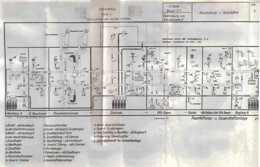
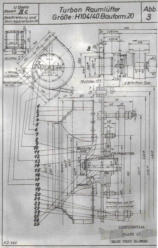
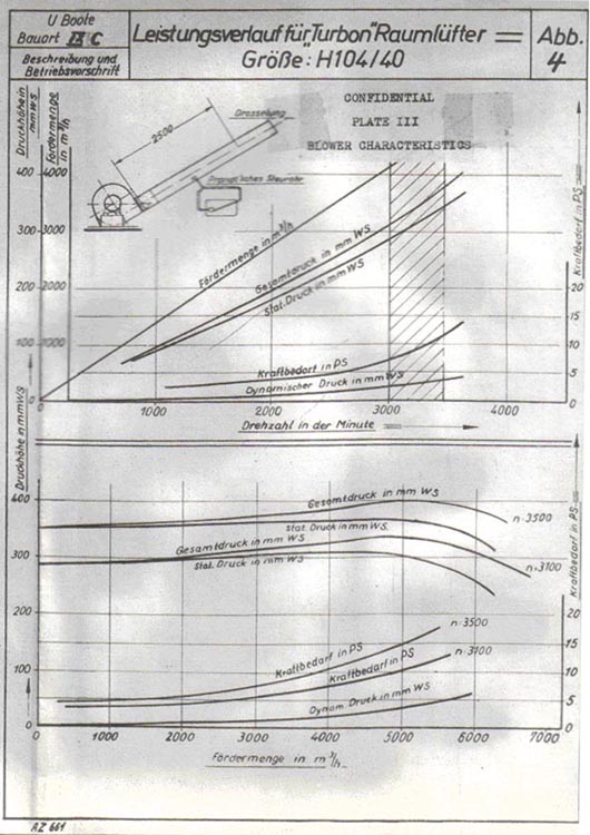
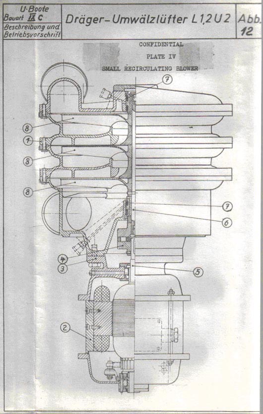 |
|
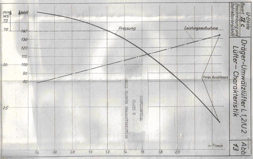
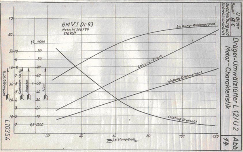
|
|||||
FORMER GERMAN SUBMARINE TYPE IX-C |
|||||
INSULATION AND LAGGING |
|||||
SUMMARY |
|||||
| Neither the type nor the amount of insulation lagging present anything of interest. Very little of either is employed, and where employed it has not been provided in such a manner as to obtain maximum effect. | |||||
July, 1946 |
|||||
PORTSMOUTH NAVAL SHIPYARD, PORTSMOUTH, N. H. |
|||||
- 1 - |
|||||
9C-S39 |
||
| 1. Description | ||
| Neither lagging nor insulation is employed to any great degree. | ||
| Glass fiber batt lagging, with a covering of glass fiber burlap secured in place by backs of soft iron wire, is used to insulate the main engine and diesel compressor exhaust piping from the operating unit up to and including the inboard exhaust valves. | ||
| The same material is used to insulate the hot sea water line to the galley. | ||
| The thickness varies from a maximum of about two inches on the inboard exhaust valves down to about 1/2 inch on the water pipe. | ||
| Granulated cork insulation is provided for the refrigerator storage compartment. About four inches of insulating material is used, with an aluminum foil backing on the surrounding structure. | ||
| The radio and sound rooms are sound insulated by .78" match boarding backed by .78" block cork. | ||
| Magazine insulation is limited to that obtainable by a .78" wooden lining. | ||
| The foregoing is the extent of the insulation and lagging provided, as such. Some minor insulating effect is obtained by the compartment lining, which consists of thin panels of fire-resistant pressed wood laid on furring pieces to provide an air space of about 2 inches between the pressure hull and the lining. This lining is not installed throughout the vessel. | ||
| 2. Comment | ||
| Both insulation and lagging are reduced to barest essentials, and it is quite obviously not considered very important by the Germans. | ||
- 2 - |
||
|
|||||
FORMER GERMAN SUBMARINE TYPE IX-C |
|||||
MACHINERY PLANT |
|||||
SUMMARY |
|||||
| The machinery plant on the IXC has been designed to provide a maximum sustained surface speed of 19 knots and a submerged speed of 7.5 knots at the one hour rate. This has been accomplished with a direct drive arrangement of a diesel engine and main motor on each of two shafts and a battery of 124 cells. The submarine has a cruising radius of 16,800 nautical miles at 10 knots. | |||||
| The machinery arrangement does not provide the flexibility of operation equal to that on U.S. submarines. The units installed, however, give the vessel similar speed and range characteristics under varying submerged and surface conditions. The associated fuel, lub oil and circulating water systems are much simpler than corresponding U.S. systems and much additional reliance is placed on operating personnel to insure their proper operation. | |||||
July, 1946 |
|||||
PORTSMOUTH NAVAL SHIPYARD, PORTSMOUTH, N. H. |
|||||
- 1 - |
|||||
9C-S40 |
||||||||||||||||||||||||||
| 1. Introduction | ||||||||||||||||||||||||||
| The propulsion arrangement on the type IXC German submarines is similar to that of its predecessor, the smaller VII-C. However, the machinery layout has been designed to provide an increase in surface speed and cruising range at no sacrifice to submerged characteristics. | ||||||||||||||||||||||||||
| 2. General Description | ||||||||||||||||||||||||||
| The propulsion characteristics on the type IXC vessel are closer to those of present U.S. designs than those of any other German type. The comparative characteristics are listed in following table: | ||||||||||||||||||||||||||
|
||||||||||||||||||||||||||
| The direct drive arrangement has a 2170 HP nine-cylinder MAN diesel engine coupled to the main motor and to the shaft through appropriate clutches. Each main motor when operating as a motor has a rating of 493 HP and when operating as a generator can develop 710 HP. The two batteries, of 62 cells each, have the capacity to furnish, at the one hour discharge rate, the rated motor horsepower to the two main motors. | ||||||||||||||||||||||||||
| The limitations that have been found to exist with a direct drive set-up on former S-boats apply as well to the German arrangement. However, it is believed that a well balanced power plant for both surface and submerged propulsion is provided and that the space and weight requirements of the comparatively high powered propulsion plant are at a minimum for this small vessel. | ||||||||||||||||||||||||||
| The associated servicing systems are, for the most part, of comparatively simple design and have been provided with a minimum of standby facilities. Some added flexibility has been gained, however, by the practice of providing standby and emergency service through numerous portable hose connections on the various systems. | ||||||||||||||||||||||||||
- 2 - |
||||||||||||||||||||||||||
9C-S40 |
||
| and by the design of piping systems to permit use of several of the pumps on more than one system. The lub oil system is simplified in that all units within the maneuvering room utilize gravity lubrication. The circulating water system is also simplified in that salt water cooling is used throughout; there are, however, numerous places within the system wherein salt water leaks can cause serious casualties. The fuel oil system employs the simplified gravity feed tank arrangement formerly used on U.S. vessels. The lack of means for adequate oil purification is a weakness in this system. | ||
| Some consideration has been given to possible casualties to the systems arising during depth charge. All hull valves have inboard back-up valves; these valves and interconnected piping are tested at 2-1/2 times designed submergence pressure. Many of the system units have been shock mounted on rubber mounts. However, no special attempt has been made to keep fuel lines outside of the ballast tanks or compensating water piping between tanks within the pressure hull. | ||
| 3. Conclusions | ||
| The IXC propulsion arrangement is considered a satisfactory compromise to obtain the desired propulsion characteristics in such a small "fleet" submarine. The layout, however, is conventional in nature and offers little that is new for discussion. | ||
| The circulating water, lub oil and fuel oil systems are, in general, considered much inferior in design to the corresponding systems on U.S. vessels. Only isolated details of the system are of interest. | ||
- 3 - |
||
|
|||||
FORMER GERMAN SUBMARINE TYPE IX-C |
|||||
DIESEL ENGINE INSTALLATION |
|||||
SUMMARY |
|||||
| Two large MAN diesel engines, each rated at 2170 HP and 470 RPM, are installed on the IXC submarine. The engines are built for rugged service. The peak and mean effective pressure per cylinder is high because of the installation of high speed superchargers. Water jackets require particular care as the engine is cooled by salt water. Furthermore, the engine must withstand high back pressures that are necessary when it is being used for producing exhaust gas for blowing ballast tanks. | |||||
| The air induction and engine exhaust systems, as altered, were able to function for surface and submerged operations. The installation for surface operation is more or less standard in nature. For submerged operation a folding type snorkel was installed. Its installation was accomplished without an excessive amount of change in either the engine or in any associated systems. | |||||
July, 1946 |
|||||
PORTSMOUTH NAVAL SHIPYARD, PORTSMOUTH, N. H. |
|||||
- 1 - |
|||||
9C-S41-5 |
||
| 1. Introduction | ||
| No attempt will be made in this section to either describe in detail the diesel engine or comment on particular features of its design. A six cylinder MAN engine, that has the same cylinders, pistons and attached pumps, and is, in most other respects, similar to the nine cylinder engine on the IXC, was installed on the XXI submarine and is to be reported on by the Engineering Experiment Station. Furthermore, complete details, descriptions and operating instructions are contained in the "Description and Operating Instructions for the M9V 40/46C and N9V 40/46 CB Diesel Engines for U Boats Type IXC and IXD2, volumes I and II". The major part of this report will be concerned with the adjuncts to the diesel engine that are peculiar to its installation on the submarine, in particular, the air induction and exhaust systems. That part of the exhaust system related to the blowing of main ballast tanks is discussed in detail under the S49 section of this report. | ||
| 2. General Description | ||
| Two nine-cylinder, supercharged four-cycle MAN diesel engines with salt water cooling are installed on the IXC submarines. On some vessels of this class the supercharger is driven by an exhaust turbine and on others it is driven mechanically. The diesel engines provide power for propulsion or battery charging on the surface and submerges (running on snorkel) and provide exhaust gas for blowing main ballast tanks after surfacing. (In lieu of low pressure air). | ||
| The snorkel operation was not contemplated in the original engine design as it was an alteration made after the vessel was placed in service. The original diesel design had two sets of cams, one for ahead and one for astern operation. When the snorkel was installed on the submarine the reverse cam on the diesel engine was removed and a "snorkel" cam was put in its place. This special cam, by decreasing valve overlap, keeps the exhaust gas temperatures within allowable limits during periods of high back pressure. The exhaust temperatures on the German MAN diesel run considerably higher than on the U.S. submarine diesels, maximum temperatures are 1022°F and 770°F respectively. | ||
| A vibration damper and vibration indicator are on the forward end of the crankshaft. The damper is a mass inertia flywheel type with eight individual sets of leaf springs serving as the coupling agent. Information on the indicator is contained in the S65 section of the IXC report. | ||
- 2 - |
||
9C-S41-5 |
||
| Each diesel engine normally has a 200 liter (7.06 cu. ft.) starting air flask. The flasks provided are filled from the high pressure air line through a reducing valve set at 1060 psi. A second reducing valve is inserted in the line to the diesel engine to decrease the pressure to 426 psi. | ||
| Two main air induction lines (port and starboard) run from immediately aft of the conning tower, along the outboard side of the pressure hull, and into the engine room at the forward end of the diesels. The head valve lies just beneath the bridge deck. To give added spray protection an air intake chute leads from this valve up through the conning tower fairwater. The air induction pipe has an inside diameter of 20 in. and wall thickness of .236 in., and is tested to 355 psi so as to be able to take some additional depth charge pressure over and above submergence pressure. Flanged construction is used throughout; all parts are made from medium steel and are galvanized. Inboard of the hull valve the air passes through a flat rectangular duct (55 in. x 8.9 in.) that follows the contour of the hull to a point below the floor plates. This serves to direct all water spray into the bilges. | ||
| The head valve and hull valve are very similar in construction. They both close with pressure and have a sloping seat. Dovetail type rubber gaskets are used on the disc; a special brass composition (similar to U.S. manganese bronze) is used for the valve seat. Both valves are hand operated and have built-in locking features. The valve bonnet for the head valve is part of a short bell-shaped casting that is secured to the induction piping and contains the valve seat. A drain connection leads inboard from a point directly below this valve. | ||
| The valve bonnet for the hull valve is part of a casting to which the inboard duct is secured. The casting serves to bring about a change in direction to the air as it comes inboard and passes into the rectangular duct. The valve housings, discs, etc., are made from a good grade of medium steel. | ||
| Independent port and starboard exhaust systems are installed. The exhaust from each engine passes through an inboard and outboard exhaust valve, through the muffler, a damper, an exhaust elbow, spark arrestor, and then overboard through openings just below the main deck level. All units are waterjacketed. | ||
- 3 - |
||
9C-S41-5 |
||
| A galvanized steel line from the exhaust gas elbow between the inner and outer exhaust valves leads to the main ballast tank blow manifold and snorkel mast. A cutout valve is installed on the line where it leaves the elbow. The port and starboard lines are joined before they reach the main blow manifold. The line to the snorkel mast is connected to this common line; a stop valve is installed to permit securing the exhaust to the snorkel when it is not in use. | ||
| The exhaust valves, the piping between them and the waterjacket on the inboard valve are tested at 284 psi. The exhaust line between the exhaust elbow and the snorkel mast exhaust valve and main blow manifold is tested at 142 psi for tightness and 213 psi for strength. The exhaust piping and fittings aft of the outboard exhaust valve, and all external circulating water piping and water jackets are tested at 28.4 psi. | ||
| The inboard exhaust valve is made up in two sections. The lower section contains the valve seat and disc. The upper section acts as a housing for the valve disc when the valve is opened. The valve operates on a counterweighted hinged principle; a lever that is keyed to the hinge shaft is used to open and close the valve. Provision is made for rotating the valve disc on its seat, the rotation serving to clean the carbon from the seat and to provide a slight amount of grinding in. A worm keyed to an inner hinge shaft meshes with the geared periphery of the valve disc. A ratchet arrangement on the same hinge shaft provides the means for giving the circular rotation to the disc. A special tightening arrangement is also provided for the valve when it is in the closed position. Leverage is applied to a bell crank, that is keyed to the outer hinged shaft, through a hand-wheel and its threaded shaft. | ||
| The outboard exhaust valve also works on the hinged principle and has a similar grinding in arrangement. The main difference between the two valves lies only in the method of transmitting the motion to them for opening and closing as well as for rotating. The outboard valve is opened by a handwheel that transmits its rotation through a gear-and-crank arrangement to the hinged shaft of the disc. Tightening of the valve on its seat is accomplished directly by the handwheel in this case. When the valve is opened the disc is housed in a recess. In lieu of a ratchet arrangement to provide rotation to the disc a handwheel arrangement is used. The handwheel | ||
- 4 - |
||
9C-S41-5 |
||
| is geared directly to the inner hinged shaft on which the worm that rotates the disc is located. A spring is attached to the hinged shaft to take the weight of the disc when it is being closed. | ||
| All cutout valves in the exhaust line with the exception of those in the main blow manifold have provision for rotation of the valve disc on its seat. It is accomplished on the smaller valves by an inner shaft that is keyed to the valve disc and which passes through the center of the valve handwheel. Small drain and vent valves as well as the direct exhaust valves have this feature. | ||
| A dry type muffler was designed for installation on the IXC and IXD2 vessels. The muffler is built in two circular sections. The inner section consists of three separate cylinders spaced longitudinally and joined by small radial fins. The outer section is the muffler shell proper and its water jacket. In cross-section the inner cylinder and the shell form concentric circles with approximately equal gas volumes within the inner and outer gas space. Zincs are installed to reduce corrosion of the muffler. | ||
| All expansion in the exhaust piping, both before and after the muffler, is taken up in the muffler. The foundation for the latter is rigidly attached to the outer waterjacket. Expansion between the waterjacket, muffler shell and inner inserted cylinders is provided at the after end by a packing gland, and between the inner and outer shell by another gland at the forward end. Packing glands are also provided at the forward and after ends of the muffler where the main exhaust piping leads into it. Means for ready flooding on diving and for venting and draining the waterjackets is also provided. | ||
| The exhaust damper is installed primarily for use when blowing ballast tanks. It permits a ready regulation of both the volume and pressure of the exhaust gases that pass to the blow manifold and thus minimizes the variation necessary in engine output. Without the damper, wire drawing through one of the main exhaust valves would be necessary which would, in turn, soon ruin the seat. The damper is controlled by a handwheel in the engine room which imparts rotary motion to it through a gearing and crank arrangement. | ||
| The spark arrestor is a simple device for causing the sparks in the exhaust to be deposited in a pool of | ||
- 5 - |
||
9C-S41-5 |
||
| water. Circular baffles direct the gasses entering the arrestor into the bottom of the large casing in which the water level is kept essentially constant. Baffles on the outboard side of the arrestor direct the gas flow over the side. | ||
| Two inboard grease manifolds are installed for use with the operating gear in the exhaust gas system. One manifold services all bearings, gears, shafts etc. forward of the mufflers and the other services those parts aft of the muffler. The piping and fittings are tested to 284 psi. | ||
| 3. Snorkel Installation | ||
| Considerable information on snorkel developments and installations is contained in NavTechMisEu Technical Report 517-45. Also much test data and information is being gathered at the Engineering Experiment Station. | ||
| A number of different types of snorkel installations have been installed on the type IXC submarines. All of this class in U.S. custody had the folding type snorkel incorporating original design features. These features included the float type of head valve and the air induction outlet from the mast at the bridge level, necessitating a gasket fit between the mast and the external air piping with the mast in the raised position. The snorkel mast is located on the starboard side of the vessel abreast the after periscope. On this class the mast rotates about a transverse axis at its base and houses in the forward superstructure. The mast is approximately 28 ft. long and has a teardrop cross-section, 13" x 27" (approx.). The forward cylindrical part is for air intake and the remaining after section is for exhaust. The air intake valve is at the top and functions on a simple ball float and lever arrangement; i.e., when the float is submerged its buoyancy closes the valve, and when it is in the air its weight opens the valve. The exposed head is approximately 25" x 45" in horizontal cross section. A small radar detecting antenna is attached to the head fitting and projects approximately 12" above the top of the mast. The exhaust outlet is about 51 inches below the air intake and is fitted with a head to deflect the gases downward and distribute them as widely as possible. The air outlet is located at a point on the mast just below the bridge level. A rubber gasket on the flanged face of the outlet seats against a raised portion on the stationary air induction pipe flange that it meets when the mast is raised. The mast is hinged at the bottom and rotates | ||
- 6 - |
||
9C-S41-5 |
||
| on two bearings. The short shaft that is necessary at the bottom of the mast is hollow, and forms the inlet to the mast for the exhaust gases. A stuffing gland is formed between the rotary and stationary sections of the exhaust piping. | ||
| A hydraulic piston and lever arrangement is used for raising and lowering the mast. A lever arm is attached to the center and at the front of the lower housing; it has an effective length of 26.4 ins. and swings through an arc of 94" on raising the mast. The hydraulic cylinder has a bore of 9.85 ins. and is approximately 5 ft. overall in length. The piston has a stroke of 37.2 ins. The piston packing as well as the piston rod packing consists of two sets of "neoprene" chevron type gaskets (single lip); the sets are opposed and therefore seal from both directions. A small drain off connection leads from the center of the rod seal to inside the pressure hull and acts to limit salt water contamination of the hydraulic oil. A cross-head and crank are attached to the piston rod to give the necessary motion to the snorkel mast lever arm. | ||
| The air induction line that leads from the mast is connected into the top of the ship's outboard ventilation valve. A separate valve and strainer are attached to this line for use in flooding the mast prior to lowering it. A separate crossover line leads from the ventilation air induction line to the engine air induction line. Thus, when operating the system it is necessary, with this setup, to open both the outboard ventilation induction valve and either the inboard engine or ventilation air induction hull valves. | ||
| The exhaust line from the mast directly to the snorkel exhaust gas valve previously mentioned. | ||
| During operation the ship should e submerged to the depth that brings the waterline between the air inlet and exhaust openings so that the gases will exhaust underwater. This will provide constant cooling of all ducts carrying the hot exhaust gases. | ||
| An improvement in snorkel mast design on other vessels is incorporated in the elimination of the gasketed joint at the air outlet. The air outlet was put in the bottom swivel joint opposite that of the exhaust; a similar packing gland to that on the exhaust side was installed between the rotary and stationary parts. | ||
- 7 - |
||
9C-S41-5 |
||
| The float type valve proved dangerous and did not provide the rapidity of valve action desired. Whenever an appreciable vacuum built up in the vessel the external air pressure would tend to seat the valve. This would accentuate an already bad condition as the engines would be forced to draw more air from the vessel and thus further increase the vacuum. | ||
| Snorkel operation was carried on in one of three normal ways as follows: | ||
| (a) Running one engine and its motor as a generator. The power supplied was used to carry a float on the battery and at the same time to run the motor on the opposite shaft for propulsion. | ||
| (b) Running one or both engines for propulsion alone. | ||
| (c) Running one engine for battery charge and the other engine for propulsion. | ||
| The operation of the plant when running on the snorkel is as follows: | ||
| (a) The water in the air intake part of the mast is drained into the vessel. | ||
| (b) The exhaust line between the inboard exhaust valve and the engine is drained. | ||
| (c) The engine is started and the back pressure is allowed to build up to approximately 10 psi at which time the inboard exhaust valve and the snorkel valve near it are opened. This will force any water in the exhaust elbow or horizontal line to the mast toward the snorkel foot valve. When the pressure is re-established the foot valve is then cracked to permit the exhaust pressure to blow the water out of the exhaust side of the mast. Full control on the operation is maintained with the foot valve. If the head of water at this point is too great so as to require back pressures that will stall the engines the valve can be secured and the head pressure will be released from the engine. Even though the engine may have stalled it will not flood because of the volume of exhaust | ||
- 8 - |
||
9C-S41-5 |
||||||||||||||||||||||||||
| gases in back of the water. Unless the snorkel mast is well under water (10 ft. or more) the head pressure is not in excess of the back pressure that can be built up by the engine, so that under normal circumstances the water is ejected in several seconds and the engine is operating under low back pressures. No trouble is encountered with the exhaust line thereafter unless the engine stops for some other reason as the water heads involved are slight compared to those present on starting. As for the air intake line, once it is initially drained, the water that gets into it during operation is removed by the inboard drain on the water trap. The most serious condition arises when the valve sticks open after it submerges in which case the overflow from the trap goes into the engine room bilges. The size of the trap and its drain line however should be sufficient to handle most of the water. Should the ship's ventilation blowers be taking a suction directly from the induction line they may receive a slug of water that will damage the impeller. | ||||||||||||||||||||||||||
| On some of the German submarines provisions are made for blowing the supply and (or) exhaust sides of the mast with air, and for draining the exhaust line inboard. These give additional means for eliminating the water in the mast and the external piping and, thereby, insure easy starting of the engines for snorkel operation. In practice, however, the normal procedure is that outlined above. | ||||||||||||||||||||||||||
| 4. Individual Components | ||||||||||||||||||||||||||
| (a) Diesel Engine | ||||||||||||||||||||||||||
| (1) General characteristics | ||||||||||||||||||||||||||
|
||||||||||||||||||||||||||
- 9 - |
||||||||||||||||||||||||||
9C-S41-5 |
||||||||||||||||||||||||||||||||||||||||||||||||||||||||
| (2) Ratings with Gas Turbine Supercharger | ||||||||||||||||||||||||||||||||||||||||||||||||||||||||
|
||||||||||||||||||||||||||||||||||||||||||||||||||||||||
| (3) Ratings with Mechanically Driven Supercharger | ||||||||||||||||||||||||||||||||||||||||||||||||||||||||
|
||||||||||||||||||||||||||||||||||||||||||||||||||||||||
| (4) Working Cylinder | ||||||||||||||||||||||||||||||||||||||||||||||||||||||||
|
||||||||||||||||||||||||||||||||||||||||||||||||||||||||
| (5) Valve timing | ||||||||||||||||||||||||||||||||||||||||||||||||||||||||
|
||||||||||||||||||||||||||||||||||||||||||||||||||||||||
| (6) Exhaust Gas Turbine Supercharger | ||||||||||||||||||||||||||||||||||||||||||||||||||||||||
|
||||||||||||||||||||||||||||||||||||||||||||||||||||||||
| 5. Conclusions | ||||||||||||||||||||||||||||||||||||||||||||||||||||||||
| The diesel engine selected for the IXC has several interesting compromises in design. In order to obtain the high power desired in each of the two engines for the limited direct drive RPM it was necessary to highly supercharge the engine. This was accomplished effectively by | ||||||||||||||||||||||||||||||||||||||||||||||||||||||||
- 10 - |
||||||||||||||||||||||||||||||||||||||||||||||||||||||||
9C-S41-5 |
||
| by the exhaust turbine supercharger. However, in so doing, design limitations in engine size required the acceptance of high exhaust temperatures for a submarine installation. The resultant mean effective pressure and power for each cylinder are high, and the fuel rate over a wide range of operation is low. | ||
| The practicability of the use of a snorkel with the diesel engine for submerged propulsion and battery charging was proved by the installations on this and other earlier types of submarines. Although serious difficulties arose from the first installations, they were operated with considerable success and pointed the way to improvements in the snorkel design to make its use less hazardous. It gives the submarine that has such an alteration a marked advantage in well patrolled enemy waters over one that is not so equipped. | ||
| The features of the design of both the exhaust gas and the air induction systems as they tie into the snorkel installation are of interest. However, in general, the systems as used for surface propulsion are standard in nature and are of little exploitation value. | ||
- 11 - |
||
|
|||||
FORMER GERMAN SUBMARINE TYPE IX-C |
|||||
REDUCTION GEARS |
|||||
SUMMARY |
|||||
| No reduction gars are used with the main propelling machinery on this type. | |||||
May, 1946 |
|||||
PORTSMOUTH NAVAL SHIPYARD, PORTSMOUTH, N. H. |
|||||
|
|||||
FORMER GERMAN SUBMARINE TYPE IX-C |
|||||
SHAFTING AND BEARINGS |
|||||
SUMMARY |
|||||
| The shafting and clutching arrangement for the Type IX-C is that required for a direct drive vessel. Standard practices are used in the design and layout of the component parts of the system. | |||||
| A stern tube gland tightening arrangement similar to an experimental one on U.S. submarines has been installed permanently on this class of vessel. | |||||
May, 1946 |
|||||
PORTSMOUTH NAVAL SHIPYARD, PORTSMOUTH, N. H. |
|||||
- 1 - |
|||||
9C-S43 |
||||||||||||||
C O N F I D E N T I A L |
||||||||||||||
SHAFTING AND BEARINGS |
||||||||||||||
| 1. GENERAL DESCRIPTION | ||||||||||||||
| A twin-screw propulsion arrangement is installed on the IX-C. The shafting setup is shown on Plate I. Each of the diesels when running at rated speed (470 RPM) transmits 2200 H.P. to the main shaft. The friction clutch forward of the main motor is operated by pneumatic hydraulic action while that aft is hand-operated. The main propeller thrust bearing and shaft brake shown are both of standard design. The stern tube and strut bearings are inlaid with lignum vitae. The outboard shaft is rubber-covered; that part between the stern tube and strut bearings is wrapped with light wire. | ||||||||||||||
| 2. INDIVIDUAL COMPONENTS | ||||||||||||||
| a. Shafting | ||||||||||||||
| The shaft line runs at an angle of 0°40' to the centerline and 0°0 to the base line. The main and propeller shaft dimensions are as listed below: | ||||||||||||||
|
||||||||||||||
| The shafts are made from a martinsitic forged steel with the following characteristics: | ||||||||||||||
|
||||||||||||||
| b. Stern tube | ||||||||||||||
| The stern tube consists of a forward and after cast steel bearing connected by a steel tube. The bearings have bronze bushings inlaid with lignum vitae on the lower third of the bearing. A circulating water connection is led to the bearing for flushing and cooling purposes. A standard stuffing gland is employed for the insertion of packing rings. The gland is tightened by means of a spur gear arrangement which insures uniform tightness of all tightening bolts. | ||||||||||||||
- 2 - |
||||||||||||||
9C-S43 |
||
| The designed stern tube and strut bearing clearance is 1 mm (.040 ins.); operating instructions available call for renewal after 3.5 mm (.140 ins.) wear. | ||
| c. Main thrust bearing | ||
| A standard main thrust bearing is installed employing ten individual shoes and capable of absorbing 33000 lbs. thrust at 500 shaft RPM. It is self-lubricated and has a built-in cooling system for cooling the lubricant. The gearing for the shaft revolution indicator is built into the thrust bearing housing. | ||
| d. Main and diesel couplings | ||
| Standard cone type friction couplings are used. To provide the quick operation necessary for uncoupling of the diesel from the main shaft a combined pneumatic-hydraulic setup is employed. This consists of a hydraulic oil cylinder operating in conjunction with an air on oil cylinder, a common German practice. Hand operation is also provided for emergency use. The main coupling is operated by hand crank arrangement. Both of the units are designed to function at a maximum torque of 94,000 lbs. ft., equivalent to 25% overload. Operating instructions state that the clutches should not be engaged when turning the shaft above 350 RPM. They may be disengaged at any RPM. | ||
| 3. CONCLUSIONS | ||
| The shafting arrangement is standard in nature for a direct drive submarine. The major deviation from normal U.S. practice is in the use of lignum vitae for the lower third of the strut and stern tube bearings. This provides a conservation of lignum vitae but results in an undesirable "combination" bearing. | ||
| A similar tightening arrangement for the stern tube gland to that installed on the IX-C has been installed on some U.S. submarines and is recommended for adoption on all submarines, especially inasmuch as it provides a ready means for changing the pressure on the packing under varying operating conditions. | ||
- 3 - |
||
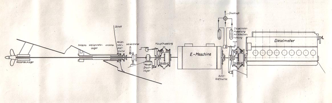
|
|||||
FORMER GERMAN SUBMARINE TYPE IX-C |
|||||
PROPELLERS |
|||||
SUMMARY |
|||||
| Twin three-bladed screw propellers of standard design are installed on the IX-C. Only limited information as to their design and operating characteristics is available. | |||||
May, 1946 |
|||||
PORTSMOUTH NAVAL SHIPYARD, PORTSMOUTH, N. H. |
|||||
- 1 - |
|||||
9C-S44 |
||
C O N F I D E N T I A L |
||
PROPELLERS |
||
| 1. INTRODUCTION | ||
| Instruction books and general arrangement plans form the only readily available source of information on the IX-C propellers. The data contained in this report is therefore limited to that contained within these sources. | ||
| 2. GENERAL DESCRIPTION | ||
| The IX-C submarine is propelled by twin screws. They are solid three-bladed propellers made from cast bronze having a specified tensile strength of 71,000 psi and an elongation of 20%. The propeller diameter as measures from available plans is 71.0 ins. The pitch or exact blade shape is not known. The center of the propeller hubs are 46.4 ins. from the centerline, 49.1 ins. above the base line, and approximately 28.9 ft. forward of the stern. The approximate minimum distance from blade tip to ship's hull is 5.9 ins. Each propeller develops a thrust during surface operation of 33,000 lbs. at 500 rpm and when going ahead turns outboard. | ||
| The screws are secured to the shaft on a tapered surface with a standard lockwasher and nut. The propeller cone is filled with tallow. A special rubber gasket is set between the propeller hub and the rubber coating on the shaft to prevent leakage of sea water into the hollow shaft. | ||
| 3. CONCLUSIONS | ||
| There are no particular noteworthy features peculiar to the design or installation of the propellers on this type of submarine. | ||
- 2 - |
||
|
|||||
FORMER GERMAN SUBMARINE TYPE IX-C |
|||||
LUBRICATION |
|||||
SUMMARY |
|||||
| On the IX-C submarine the diesel engine and its associated machinery have a forced lubrication system and an oil purifying arrangement while each of the remaining propulsion components requiring lubrication, namely, the main motor bearings and the main thrust bearings, has a self-contained gravity system. | |||||
| The lub oil system used with the diesel engine and its components is for the most part standard. Piping layouts are similar to those on Electric Boat Company designs, especially with regard to an extensive use of central manifolds. Filters, strainers, oil purifiers and oil coolers are similar to available U.S. commercial equipment. Total storage tank capacity is equivalent to U.S. submarine standards; however, individual diesel engine sump tanks are much shorter and of only half the storage capacity. The major differences from U.S. submarine practice are in the installation on the German vessels of a contaminated oil system, and the use of portable hose and interchangeable pipe connections to permit use of the hand and power driven detached pumps with fuel oil or other systems. In addition, salt water cooling of the main engine lubricating oil is used, compared with the more elaborate fresh water system for that purpose on U.S. submarines. | |||||
June, 1946 |
|||||
PORTSMOUTH NAVAL SHIPYARD, PORTSMOUTH, N. H. |
|||||
- 1 - |
|||||
9C-S45 |
||
C O N F I D E N T I A L |
||
LUBRICATION |
||
| 1. GENERAL DESCRIPTION | ||
| The forced lubrication system on the IX-C submarine is tied in with an oil purifying arrangement in a manner similar to U.S. submarine practice. However, within both the lubrication and purifying systems, i.e: in tank design and in piping layouts, several basic and numerous minor differences exist. | ||
| On each IX-C there are three lub oil storage tanks containing a total of 2620 gals. when 95% full, two diesel engine sump tanks containing a total of 418 gals. when 75% full, and a contaminated oil tank of 296 gals. capacity. Two of the storage tanks are in the forward end of the pump room and the third is on the after port side of the battery room. They are of light construction and tested at 11.4 psi. The port and starboard engine sumps are set low within the pressure hull, extend beyond the centerline of the compartment in a transverse direction and run fore and aft less than one-third the length of the diesel engine (6.5 ft.). The contaminated oil tank is 9.8 ft. long and is set aft of the sump tanks in the center of the compartment. On late Electric Boat and Portsmouth designs each main engine sump is built the full length of the engine and contains 382 gals. and 442 gals. respectively - nearly double the IX-C sump capacity, although the diesel engine is smaller and of lower rating then the German diesel. | ||
| The fuel oil is transferred from the storage tanks to the individual sumps by a lub oil transfer pump or, in emergencies, by a hand lub oil pump. Three distribution manifolds are located in the engine room adjacent to the pumps - one manifold to select the storage tank to be used, a second one to permit use of the hand or transfer pump for flushing of the main engines and a third master manifold tying in the pumps with the above two manifolds, the lub oil filling line and the individual engine sumps. On the suction and discharge sides of the transfer pump there are two short sections of lub oil piping that can be removed and replaced by two sections of different shape which tie directly into the fuel oil transfer system, thereby permitting the use of the pump for transferring either lub or fuel oil. Portable hose connections on the | ||
- 2 - |
||
9C-S45 |
||
| suction and discharge side of the hand lub oil pump permit the additional use of the pump with the fuel oil and circulating water systems. | ||
| The forced lubricating system is very similar to the corresponding U.S. system and differs only in minor details. The system is similar to U.S. practice in that the attached pump take a suction from the sump through a stop-check valve and discharges the oil through an oil cooler and knife-edge filter to the engine. Also, there is a relief valve (set at 42.6 psi.) on the pressure side of the pump and a bleed off line to the transfer pump and oil purifying system. However, in addition, the systems on the IX-C are cross-connected (a former U.S. practice when only two diesels were installed) and a second pressure relief valve (set at 56.8 psi.), with a discharge to the sump and located on the discharge side of the lub oil cooler, limits the pressure of the oil entering the engine. (The circulating water pressure is at all times kept below that of the lub oil.) No pressure bypass around the coolers is used and the differential pressure gauge normally around both coolers and filter is placed only around the knife-edge filter. "Cuno" type filters and circular tube, multi-pass oil coolers are used. The IX-C coolers have much less total cooling surface area then the U.S. submarine coolers, mainly because of the use of fresh water cooling on the latter. | ||
| The oil purifying system on the IX-C is of much lower capacity and is arranged to function in a somewhat different manner from the system as set up on U.S. submarines. A single, standard DeLaval purifier, rated at 79.2 gals./hour is installed, while on U.S. vessels two 250-gals./hour purifiers are used. The piping, pumps and heaters on the IX-C purifier system form an independent system and the units are selected with only that one service in mind, whereas the purifier pump and heater on U.S. vessels are of greater capacity than required for purification alone and are piped so as to be used also for transferring and heating oil from storage of sump tanks. This dual service requires the installation of a "flow" regulating valve that isn't required with the IX-C arrangement. A further difference exists in that the German purifier functions on a separator principle requiring a separate salt water feed line and salt water heater that need be kept in constant use and adjustment. The Sharples purifier on U.S. vessels is presently used only as a clarifier and does not require a separate salt water feed line. The German purifying arrangement with temperature and flow regulation on both the lub oil and salt water | ||
- 3 - |
||
9C-S45 |
||
| lines requires more attention during operation then on the U.S. setup with only temperature regulation on the lub oil line. | ||
| The contaminated oil system installed is tied into the lub oil purifying and transfer systems. In addition to the tank previously mentioned, a hand pump is also provided. There are four separate pipes connected to the contaminated oil tank, namely, discharges from the purifier and auxiliary drain pump, a common suction and discharge to the lub oil transfer line, and a vent line. The hand pump can take suction from the transfer line or directly from either of the engine sump tanks and discharge it to the contaminated oil tank. The oil can be removed from the tank by the hand pump, purifier pump of the transfer pump. | ||
| The diesel engine is the only unit having forced lubrication, the remaining units of the propulsion system have independent built-in lubricating oil arrangements and require individual servicing. | ||
| The main motor bearings have small individual lub oil sumps (not interconnected). Fixed oil rings rotating with the shaft and bearing against radial white metal surfaces built into the bearing carry the oil to the top of the bearing. Small knife-like wipers at the top of the bearing remove the oil, whence it flows by gravity to the bearing surfaces. To provide means for cooling the bearing, circulating water tubes are imbedded into both the longitudinal and radial white metal bearing surfaces of the lower bearing shells. The thrust of the motor arising from excessive trim angles is taken by the radial bearing surfaces through the medium of the fixed oil rings. | ||
| The propeller thrust bearing has a much larger lub oil sump than that for each motor bearing. Two set of copper-nickel cooling cells, one in the sump and the other close to the under part of the bearing, are used for cooling. The oil is carried to the upper part of the bearing by the thrust collar where it is removed by wiper plates and fed by gravity to the bearing surfaces. The excess oil flows through a drain pipe to the lower part of the sump, thereby providing a desired amount of circulation. | ||
| In the German lubricating systems there are numerous places wherein salt water can enter the lub oil from leakage in the cooling water piping. The German designers were evidently aware of this prevalent source of trouble and have taken certain steps to keep it to a minimum. Their maintenance instructions call for continual inspections and | ||
- 4 - |
||
9C-S45 |
|||||||||||||||||||||||||||||||||||||
| oil sampling to detect its presence; also, corrosion of salt water piping is held in check by using anti-corrosion oil in it when machinery os left idle for short periods of time. The specifications for the type of lub oil to be used call for an oil that will not emulsify with salt or fresh water. This permits ready separation of the water from the lub oil if detected in a sump or storage tank. | |||||||||||||||||||||||||||||||||||||
| 2. INDIVIDUAL COMPONENTS | |||||||||||||||||||||||||||||||||||||
| a. Lub oil transfer pump | |||||||||||||||||||||||||||||||||||||
|
|||||||||||||||||||||||||||||||||||||
| b. Attached lub oil pump | |||||||||||||||||||||||||||||||||||||
|
|||||||||||||||||||||||||||||||||||||
| c. Lub oil coolers | |||||||||||||||||||||||||||||||||||||
|
|||||||||||||||||||||||||||||||||||||
| d. Lub oil purifier | |||||||||||||||||||||||||||||||||||||
|
|||||||||||||||||||||||||||||||||||||
- 5 - |
|||||||||||||||||||||||||||||||||||||
9C-S45 |
||||||||||||||
| e. Lub oil purifier pumps | ||||||||||||||
|
||||||||||||||
| f. Lub oil specifications | ||||||||||||||
|
||||||||||||||
| 3. CONCLUSIONS | ||||||||||||||
| The lubrication of the propulsion units on the IX-C is accomplished in a very basic manner and with the use od a minimum of weight and space. Reliance on gravity feed lubrication for all units but the diesel engines decreases the weight requirements for the lubrication of these units to a very minimum; the use of salt water cooling and simple purifying arrangements in the diesel engine lubricating system keeps the weight and space requirements of this system also at a minimum. Much care, however, is required to prevent salt water leakage into the lub oil. The simplicity, ruggedness and slow R.P.M. of the propulsion units, in particular the diesel engine, make possible the installation of such a simplified arrangement. The design and rotating speeds of corresponding U.S. equipment, however, do not permit a similar setup. | ||||||||||||||
| The use of smaller engine sumps, utilizing the space saved for a contaminated oil tank is recommended for adoption on U.S. submarines. | ||||||||||||||
| Further exploitation of the lub oil system on this type is not recommended as there are no features warranting it. | ||||||||||||||
- 6 - |
||||||||||||||
|
|||||
FORMER GERMAN SUBMARINE TYPE IX-C |
|||||
CONDENSERS |
|||||
SUMMARY |
|||||
| This section is inapplicable and the page is inserted only for record purposes. | |||||
July, 1946 |
|||||
PORTSMOUTH NAVAL SHIPYARD, PORTSMOUTH, N. H. |
|||||
- 1 - |
|||||
|
|||||
FORMER GERMAN SUBMARINE TYPE IX-C |
|||||
PUMPS |
|||||
SUMMARY |
|||||
| All pumps are considered under the systems which they serve. As for those few pumps which are specified by the Navy Filing Manual as being treated separately under this heading, the following is the situation: | |||||
| a) Fire Pumps - there are no such pumps, the fire main being served by one of the auxiliary drain pumps. | |||||
| b) Fresh Water Pumps - these are small oscillating force pumps, hand operated, of no exploitational interest, and have been considered under the description of the fresh water system. | |||||
July, 1946 |
|||||
PORTSMOUTH NAVAL SHIPYARD, PORTSMOUTH, N. H. |
|||||
- 1 - |
|||||
|
||||||||||||||||||||||||||
FORMER GERMAN SUBMARINE TYPE IX-C |
||||||||||||||||||||||||||
PIPING |
||||||||||||||||||||||||||
GENERAL REFERENCE PAGE |
||||||||||||||||||||||||||
| The piping systems appropriate to this group are discussed under their own separate sub-group headings. | ||||||||||||||||||||||||||
|
||||||||||||||||||||||||||
| It will be noted from the foregoing that certain sub-groups under S48 have not been used. This is accounted for by either the absence of such systems, or by the fact that the components discussed are integral parts of other systems discussed under other "S" groups. | ||||||||||||||||||||||||||
July, 1946 |
||||||||||||||||||||||||||
PORTSMOUTH NAVAL SHIPYARD, PORTSMOUTH, N. H. |
||||||||||||||||||||||||||
- 1 - |
||||||||||||||||||||||||||
|
|||||
FORMER GERMAN SUBMARINE TYPE IX-C |
|||||
PUMPING AND DRAINAGE SYSTEMS |
|||||
SUMMARY |
|||||
| A trim and drainage system similar in many respects to the system on U.S. submarines has been installed on the IXC submarine. The main drain, and auxiliary drain and trim pump in the control room correspond to the U.S. trim and U.S. drain pumps, respectively, although their basic functions are reversed. Some additional flexibility and capacity have been provided on the German arrangement, however, by the installation of separate centrifugal drain pumps, of limited discharge head, in the forward and after torpedo rooms. | |||||
July, 1946 |
|||||
PORTSMOUTH NAVAL SHIPYARD, PORTSMOUTH, N. H. |
|||||
- 1 - |
|||||
9C-S48-1 |
||
| 1. General Description | ||
| The German trim and drainage arrangements on the IXC submarine are divided into two interconnected systems, a main drainage system and an auxiliary drainage and trimming system. | ||
| The main drainage system is serviced by a relatively high powered four stage centrifugal pump in the control room. The pump can be operated with the four stages in series to discharge against designed submergence heads or with two pairs of stages in parallel to deliver high capacities against heads up to 50 meters (164 ft.) This pump has a small built-in centrifugal vacuum pump that can be cut in to remove air from the suction piping and obtain greater suction heads. Specifications in the pump instruction book state that the pump shall be able to place a vacuum of approximately 12 inches on a 198 gallon container in one minute. During series operation the water enters the main suction valve, passes through the first two stages (in series), then passes via an external pipe and cut-out valve to the remaining two stages. During parallel operation a cut-out valve within the pump housing is opened to permit parallel flow to the first and third stages. A second shut-out valve within the pump housing is opened to connect the discharges from the second and fourth stages. The pump is directly connected to the driving motor by a flexible coupling. | ||
| The main drain pump can take a suction from the main drain piping that services all compartments, from sea, from the auxiliary ballast tanks or from the auxiliary trim and drainage suction piping. The main drain line from each compartment leads into a master manifold in the control room. A line leads from this manifold to the main suction manifold for the drain pump. The pump can discharge to an auxiliary ballast tank, directly to sea, to No. 5 starboard ballast tank or to the auxiliary drainage and trim discharge piping. Stop-check valves that may be operated from adjacent compartments are installed on the suction piping of all compartment drain lines. Stop-check valves are also on the discharge side of the drain pump. Portable hose connections are of the suction piping in the engine room and galley. | ||
| The auxiliary drain and trimming system is divided into two independent sections, one section that is serviced by the auxiliary drain and trim pump located in the control room and the second that is serviced by the | ||
- 2 - |
||
9C-S48-1 |
||
| two small auxiliary drain pumps that are located in the forward and after torpedo rooms. | ||
| The auxiliary drain and trim pump is a ruggedly built 2-piston reciprocating pump that corresponds closely in size and service to the Gardner-Denver drain pump used on U.S. Submarines. The German pump is double acting while the U.S. one is single acting. The capacity of the German pump is materially higher than the U.S. pump while the pressure is somewhat less (150/200 psi.). The main differences are in the cylinder, and in the power transmission to the piston from the crankshaft. The IXC design has a crosshead between the piston and crankshaft. Because of this the cylinder can be sealed by packing around the piston rod. Also, the double action feature requires an additional suction and discharge valve for each cylinder. On the U.S. drain pump the piston rod connects directly to the crankshaft, which, in turn, necessitates a seal between the cylinder liner and the piston. The volume over the piston is the working surface in this case. The motor for the U.S. and the German pumps are coupled alongside and above the pump, respectively. | ||
| The pump's service is essentially as its name implies. It is used primarily as a trim pump and acts as an auxiliary pump for use on the main drain system (up to designed submergence). The pump can take a suction from either trim tank or from the main drain suction. It can discharge to the opposite tank or from the main drain suction. It can discharge to the opposite trim tank or to the main drain discharge piping. Portable hose fittings, for deck washing and for emergency service, are also on the discharge line from this pump. A flow meter is installed in the trim line. Also, a reversible exchange valve is in the trim line between the two trim tanks. This valve when set in one position sets up one tank on the suction side of the pump and the other tank on the discharge side of the pump; in the second position the operation is reversed. Several of the IXC submarines have been rigged for blowing the trim tanks. In this case a by-pass line and stop valve have been installed around this exchange valve. | ||
| The two small auxiliary drain pumps are single stage centrifugal pumps. They are meant primarily for use during surface or shallow submergence as their maximum discharge head and test pressure is limited. The pump is fitted with a similar vacuum pump as built in the main drain pump. Instruction book specifications call for this pump to develop a vacuum of approximately | ||
- 3 - |
||
9C-S48-1 |
||
| 12" in one minute in a 66 gallon container. | ||
| These drain pumps are used mainly for drainage of the forward WRT tanks, the torpedo rooms and the compartments adjacent to them. This pump discharges directly to sea through a stop-check and a hull valve. A cross connection exists between both the forward and the after auxiliary drain pump suction lines and the main drain suction line, giving added flexibility to the entire drainage system. | ||
| Additional drainage in the engine room is provided by a bilge suction connection to the standby circulating water pump. | ||
| 2. Operation | ||
| The reciprocating drain pump acts as a general service pump for handling small quantities of water. Its ruggedness makes it suitable for this duty. However, it is a comparatively noisy pump and was not to be used when in contact with the enemy. | ||
| The centrifugal drain pump in the control room was used to handle larger quantities of water. When in operating areas and subject to sound detection this pump was invariably used in lieu of the noisier reciprocating pump. To prevent slicks the contaminated water was pumped into No. 5 starboard ballast tank (this tank has been fitted with flood valves). | ||
| The small centrifugal pumps in the forward and after rooms can be used for discharging small quantities of water from the torpedo and adjacent compartments in addition to their use for pumping WRT tanks. Although they are silent pumps and can take a ready suction from these after compartments they are limited in operation by two features of design. The pumps discharge directly to sea so cannot be used to pump contaminated bilge water when the vessel is in operating areas. Furthermore, the pumps cannot discharge against heads in excess of 100 - 150 ft. (dependent on battery voltage) so that they cannot be used to take a ready suction from the forward and after compartments with a large angle on the boat when the control room pumps would lose suction on these compartments. | ||
| The centrifugal pumps can be used with air pressure to pump against heads in excess of those designed submergence (100 meters, 328 ft.). This was found necessary as the submarines were forced below this depth | ||
- 4 - |
||
9C-S48-1 |
||
| on numerous occasions. Bilge water first had to be pumped into the auxiliary ballast tank, and then pumped overboard after placing the necessary "boosting" air pressure on this tank. The machinery information book (M u E Kunde fur U Boote Bauart IXC) states that the most favourable pressure differential between intake and discharge on the main drain pump when pumping from the regulating tank at greater depths is 114 p.s.i., and that the variable tank pressure must be adjusted accordingly. The pressure given is the one at which the drain pump motor takes maximum power. | ||
| The use of the drain system is further described in the book on special wartime experience (Besondere Kriegser fahrungen - Abschmitt Maschine), in parts II and XVII, and on page 102. | ||
| In part II, devoted to depth control, mention is made of the necessity to pump while increasing depth to avoid falling beyond the desired point and a figure of 3/4 to 1 (metric) ton for 20 meters is given. This is 2520 to 3360 pounds per hundred feet, which confirms the findings of the Woods Hole Oceanographic Institution reported in their confidential letter of 14 June 1946 to the Bureau of Ships. In that letter they report that information from the Germans gave 1000 liters pumped to dive 100 meters, whereas the vessels IXC, IXD and XB they had experimented with ran, respectively 1850, 2930 and 2750 pounds for 100 feet. These figures would give, for U.S. submarines, 3600, 3900 and 3000 lbs. equivalent. | ||
| Further mention is made in the same section to the need for operating the drain pump to the limit of practicable rating "when approaching a heavy depth", and to the difficulty of draining with compressed air alone because of noise and the possibility of straining bulkheads. Recommendation is made that a pressure of 10 to 12 atmospheres be maintained on the regulating tank to relieve the head on the drain pump. | ||
| Section XVII further amplifies this operation by mention of the fact that where vessels have multiple regulating tanks available, two tanks should be rigged for drain, of which one is under a pressure of 10 to 12 kg/cm2 as a deep drain regulator and the other is carried at about 2.5 kg/cm2 for use at periscope depth. | ||
| Both section II and section XVII mention the need to apply pressure to the regulating bunkers and the negative tanks if pressures higher than 14 atmospheres are placed on the regulating tank, in order to relieve the pressure on the end bulkheads of the regulating tank, which lies between the other two. | ||
- 5 - |
||
9C-S48-1 |
||||||||||||||||||||||||||||||||||||||||||||||||||||||||||||||||||||||||||||||||
| Section II also mentions that some vessels tend to become heavy aft at greater depths and that water in the after bilges is to be pumped into the regulating tank or bunker which is not under pressure by using hose connections to the main drain or the auxiliary drain and trim pump. | ||||||||||||||||||||||||||||||||||||||||||||||||||||||||||||||||||||||||||||||||
| Page 102 of the war experience book states that the flooding of the main drain line in order to take suction from the forward or after compartments is a necessary evil, and that if proper operation is not followed the vessel can be enhazarded by flooding the battery compartment or maneuvering room. The time taken to flood the line must be known, and if it is not flooded by the end of that time there must be a leaky valve somewhere. The instructions also include a direction to watch the battery and maneuvering room bilges all during the time the main fore-and-aft drain line is flooded. | ||||||||||||||||||||||||||||||||||||||||||||||||||||||||||||||||||||||||||||||||
| 3. Individual Components | ||||||||||||||||||||||||||||||||||||||||||||||||||||||||||||||||||||||||||||||||
| (a) Main drain pump characteristics | ||||||||||||||||||||||||||||||||||||||||||||||||||||||||||||||||||||||||||||||||
|
||||||||||||||||||||||||||||||||||||||||||||||||||||||||||||||||||||||||||||||||
| (b) Auxiliary drain pump characteristics | ||||||||||||||||||||||||||||||||||||||||||||||||||||||||||||||||||||||||||||||||
|
||||||||||||||||||||||||||||||||||||||||||||||||||||||||||||||||||||||||||||||||
- 6 - |
||||||||||||||||||||||||||||||||||||||||||||||||||||||||||||||||||||||||||||||||
9C-S48-1 |
||||||||||||||||||||||||||||||||||||||||||||||||||||||||||||||||||||
| (c) Auxiliary drain and trim pump | ||||||||||||||||||||||||||||||||||||||||||||||||||||||||||||||||||||
|
||||||||||||||||||||||||||||||||||||||||||||||||||||||||||||||||||||
| 4. Conclusions | ||||||||||||||||||||||||||||||||||||||||||||||||||||||||||||||||||||
| The Germans have provided the IXC with relatively greater pumping capacity for both shallow and deep submergence than is provided on late U.S. submarines. The pumps, however, have somewhat less maximum discharge heads than in U.S. practice. The centrifugal main drain pump is of similar, but inferior, design to the U.S. Gould pump. The latter is more compact and simpler of operation. The reciprocating auxiliary drain and trim pump, however, is considered superior in design to the Gardner-Denver pump selected for use on U.S. submarines. The German pump has more than double the delivery at 3/4 the discharge pressure although the pump is lighter in weight and approximately equal in size. Packing and piston troubles are materially less with the use of the shorter piston and of piston rod packing on the German pump in lieu of the long piston and of cylinder packing on the U.S. pump. However, valve troubles will be enhanced with the use of the additional suction and discharge valves. | ||||||||||||||||||||||||||||||||||||||||||||||||||||||||||||||||||||
| The greater pumping capacity is related to the unfavorable compression ratio and to the division of the drain system into small segregated units not all of which may be available at a given moment. | ||||||||||||||||||||||||||||||||||||||||||||||||||||||||||||||||||||
| The centrifugal pumps in the forward and after compartment provide additional capacity and flexibility to the drainage system for surface and shallow submergence. However, they do not fulfill a desired function of insuring pumping facilities to these compartments when the vessel takes and appreciable angle and suction is lost by the control room pumps. Also, they could be made more effective by the provision of a discharge to a "contaminated" water ballast tank. | ||||||||||||||||||||||||||||||||||||||||||||||||||||||||||||||||||||
- 7 - |
||||||||||||||||||||||||||||||||||||||||||||||||||||||||||||||||||||
|
|||||
FORMER GERMAN SUBMARINE TYPE IX C |
|||||
CIRCULATING WATER SYSTEMS |
|||||
SUMMARY |
|||||
| Two interconnected salt water circulating systems, one for use with the diesel engines and the other with the main motors, are provided on the IX-C submarine. Salt water is used directly for cooling engine components and lubricating oil without intermediate fresh water. All parts of both systems subject to circulating water pressure are built to withstand a test pressure of at least 142 psi (corresponding to the design depth of the vessel). Certain fittings and piping are subject to higher test pressures. | |||||
| A minimum of pumps is used with the systems. Each diesel has an attached circulating water pump that services the diesel engine, its lub oil cooler, and all parts of the exhaust system; and then discharges to the compensating system head box. The main motor components requiring cooling receive their circulating water from one detached circulating water pump. The latter services the air coolers, main motor bearings, thrust bearings, Junkers air compressor, stern tube glands and distiller; and then discharges to sea. The standby pump in the engine room can service either of the systems. A separate attached pump is used to supply the circulating water to the electric air compressor. A small hand circulating pump has also been connected to the systems. | |||||
June, 1946 |
|||||
PORTSMOUTH NAVAL SHIPYARD, PORTSMOUTH, N. H. |
|||||
- 1 - |
|||||
9C-S48-5 |
||
| 1. Introduction | ||
| Some of the details of the circulating water arrangements that are associated with lub oil cooling have been covered under the S45 section, lubricating oil systems, of the IX-C report. | ||
| 2. General Description | ||
| Very simple salt water circulating systems are installed on the type IX-C submarine. All units requiring cooling are cooled by these systems as the separate fresh water cooling arrangements used with the diesel engines on U.S. submarines have not been installed. | ||
| The cooling water for the diesel engine comes from one of two sea suctions in the engine room. The sea chests are fitted with blow and venting connections. The water passes through a strainer to a common suction line for the attached, standby, and hand circulating water pumps. The discharges from all four pumps feeds into a common distribution manifold. | ||
| The discharge from each attached pump also leads directly to the lub oil cooler and thence to the diesel engines. The water passes through the water jacket on the engines, through the inboard and outboard exhaust valves, the muffler, the exhaust throttling valve, the spark arrester and thence to the head box. A recirculating line runs from the water jacket discharge to the pump suction line. A "hot" salt water line for showers, etc. leads from the inboard exhaust piping. | ||
| The distribution manifold permits one of any of the circulating water pumps on either diesel engine system or by means of the cross-connection line on the units in the maneuvering room. A hull valve at the bulkhead isolates the circulating water piping in the two rooms. | ||
| The salt water for the main motor and compressor circulating water pumps comes from a separate sea suction in the maneuvering room. The sea chest is fitted with a blowing connection. A wire mesh filter is installed in the suction line. | ||
| The main motor circulating water pump discharges to a common supply line. All units to be cooled, with one exception, receive their circulating water direct from this line. The cooling water piping for the Junkers compressor and its inboard exhaust valve is in series while | ||
- 2 - |
||
9C-S48-5 |
||
| that for the air coolers, main motor bearings, main thrust bearing, stern tube gland and distiller forms a parallel arrangement. The supply to all units is controlled by individual suction and discharge stop valves. The discharge from all units runs into a common discharge line that, in turn, leads through a stop-check and a hull valve to sea. | ||
| The circulating water from the pump on the air compressor services the compressor and then passes via a sight gauge and check valve to the common discharge line. A safety valve is placed between the gauge glass and check valve. | ||
| Several direct leads, as well as portable hose fitting, are provided in the salt water piping to permit complete flushing of the entire system with anti-corrosive oil. The details of this flushing arrangements are covered under the S19 section of the IX-C Report. | ||
| In addition to the sight gauge on the electric compressor discharge piping, gauges have also been fitted on the salt water line leading from the Junkers compressor and on a lub oil cooler vent line. These permit ready detection of leakage from the units serviced to the salt water piping. | ||
| All parts of the circulating water system are designed to withstand a basic test pressure of 142 psi, the designed depth pressure. This requires that circulating water to the main motors must be secured before this depth is reached as a pressure in excess of the above is reached at designed depths by the differential pressure of 21.3 psi from the main motor circulating water pump. The test pressure on the standby, compressor and main motor circulating water pumps on the air coolers is 142 psi or greater, while that of the piping, inboard valves, filters, safety valves and other fittings is set at the lower value. Hull valves and the connecting piping are designed to withstand a test pressure of 2-1/2 times the designed depth or 355 psi. | ||
| For the most part, salt water piping and fittings are made from galvanized steel. Hull valves in some cases are made from a special brass composition. "Warm" salt water piping used with the main motors is made from half hard copper. | ||
- 3 - |
||
9C-S48-5 |
||||||||||||||||||||||||||||||||||||||||||
| 3. Individual Components | ||||||||||||||||||||||||||||||||||||||||||
| a) Attached cooling water pump (Diesel) | ||||||||||||||||||||||||||||||||||||||||||
|
||||||||||||||||||||||||||||||||||||||||||
| b) Standby cooling water pump (engine room) | ||||||||||||||||||||||||||||||||||||||||||
|
||||||||||||||||||||||||||||||||||||||||||
|
||||||||||||||||||||||||||||||||||||||||||
| c) Main motor circulating water pump | ||||||||||||||||||||||||||||||||||||||||||
|
||||||||||||||||||||||||||||||||||||||||||
|
||||||||||||||||||||||||||||||||||||||||||
| d) Main motor air coolers | ||||||||||||||||||||||||||||||||||||||||||
|
||||||||||||||||||||||||||||||||||||||||||
- 4 - |
||||||||||||||||||||||||||||||||||||||||||
9C-S48-5 |
|||||||||||||||||
| e) Circulating water piping | |||||||||||||||||
|
|||||||||||||||||
| f) Salt water filters | |||||||||||||||||
|
|||||||||||||||||
| 4. Conclusions | |||||||||||||||||
| There are no particular noteworthy features in the circulating water systems installed on the IX-C. Although the system layout is simple in most respects, it provides a desired wide flexibility in the use of the four main circulating water pumps. Detection of leakage from several prevalent sources of trouble is possible from the installation of sight gauges on the discharges from these units. | |||||||||||||||||
| The limitation imposed on the use of the main motor circulating water system by the test pressure is a weakness in the system. Not only must the system be secured when going to deep submergence, but pressures arising from leaky valves after it is secured may readily cause rupture of vital inboard piping. This is particularly true with the piping used for cooling the main motor and main thrust bearings. | |||||||||||||||||
| The use of salt water cooling for the diesel engines and the lub oil cooler is more hazardous and subject to less temperature control than is the use of fresh water for this purpose. A measure of compensation arises from the fact that the diesel engines are of lower speed and more rugged design, and that lub oil operating pressures exceed circulating water pressures on the lub oil cooler. | |||||||||||||||||
- 5 - |
|||||||||||||||||
|
|||||
FORMER GERMAN SUBMARINE TYPE IXC |
|||||
SCUPPERS AND DRAINS |
|||||
SUMMARY |
|||||
| Drains are of standard type and generally well laid out. Tank top drains have been retained, however, and a hazard to tank integrity is thereby introduced. | |||||
July, 1946 |
|||||
PORTSMOUTH NAVAL SHIPYARD, PORTSMOUTH, N. H. |
|||||
- 1 - |
|||||
9C-S48-8 |
||||||||||||||||||||||||
| Piping from washbasins and heads is discussed in the S36 section of the report. | ||||||||||||||||||||||||
| Deck drains are provided as follows: | ||||||||||||||||||||||||
|
||||||||||||||||||||||||
| Bilge drains from equipment and fittings are provided as follows: | ||||||||||||||||||||||||
|
||||||||||||||||||||||||
| The conning tower drains, and the great majority of all other drains, are equipped with funnels to avoid siphoning suction or return flow. The only drains not so equipped are those which are well down in the ship where there is no possibility of introducing self perpetuating fluid columns or possibility of endangering equipment as a result of the drainage flow. | ||||||||||||||||||||||||
- 2 - |
||||||||||||||||||||||||
9C-S48-8 |
||
| Drains from fuel oil and lubricating oil venting and drain points are provided with funnel, piping from which leads to collecting tanks or oil cans. | ||
| The waterway between the tank tops and the pressure hull is drained by scuppers extending through the tank tops. The piping through the tanks is given an S curve to avoid making it act as part of the structure. | ||
| COMMENT | ||
| Deck drains are complete and properly located. The use of the battery wells as bilges is avoided at the expense of carrying certain drain lines through bulkheads into adjacent compartments. | ||
| Bilge drains from equipment are otherwise complete. The extensive use of pans, cans and lines to collecting tanks are evidence of the attempts made to conserve oil and prevent it from getting into the bilges. | ||
| The tank top drains do not appear to have been considered by the Germans as a hazard to tank integrity, although the installation was in effect similar to the one removed from U.S. submarines, with the same consideration for expansion. | ||
- 3 - |
||
|
|||||
FORMER GERMAN SUBMARINE TYPE IXC |
|||||
SOUNDING TUBES AND VENTS |
|||||
SUMMARY |
|||||
| Sounding and venting arrangements are normal and present nothing unusual except for the sounding tubes on drinking water tanks. | |||||
July, 1946 |
|||||
PORTSMOUTH NAVAL SHIPYARD, PORTSMOUTH, N. H. |
|||||
- 1 - |
|||||
9C-S48-9 |
|||||||||||||||||||||||||||||||||||||||||||||||||||||||||||||||||||
| Sounding tubes and vents are used, sometimes individually and sometimes with combined functions. | |||||||||||||||||||||||||||||||||||||||||||||||||||||||||||||||||||
| Arrangements installed are as follows: | |||||||||||||||||||||||||||||||||||||||||||||||||||||||||||||||||||
|
|||||||||||||||||||||||||||||||||||||||||||||||||||||||||||||||||||
| In addition, inboard vents with sight glasses and mufflers are provided for the negative and auxiliary ballast ("regel zelle" and "regel bunker") tanks. | |||||||||||||||||||||||||||||||||||||||||||||||||||||||||||||||||||
| Vents are provided inboard for each normal fuel oil tank and fuel ballast tank and for fuel oil pumps, as described under the section devoted to the fuel oil system. | |||||||||||||||||||||||||||||||||||||||||||||||||||||||||||||||||||
| Piping vents are provided at the ends of the vessel and at the suction manifold on the main drain systems and a vent is provided for each torpedo tube. | |||||||||||||||||||||||||||||||||||||||||||||||||||||||||||||||||||
| Main vents are discussed under S29 and S49 sections. | |||||||||||||||||||||||||||||||||||||||||||||||||||||||||||||||||||
| Comments: | |||||||||||||||||||||||||||||||||||||||||||||||||||||||||||||||||||
| Sounding tubes and vents appear normal in all respects except that the installation in drinking water tanks is open to question. It is of interest that the sounding tubes only in the WRT and sanitary tanks are arranged to permit suction hose connections to the drain pumps. | |||||||||||||||||||||||||||||||||||||||||||||||||||||||||||||||||||
- 2 - |
|||||||||||||||||||||||||||||||||||||||||||||||||||||||||||||||||||
|
|||||
FORMER GERMAN SUBMARINE TYPE IX-C |
|||||
PIPING |
|||||
SUMMARY |
|||||
| Valve design is conservative and simple. Basic policy evident in hull valve design is to have valves close with pressure. | |||||
| The only valve type of interest from the standpoint of exploitation locally is the high pressure air valve with the lapped collar type stem in lieu of packing. Reports on this and on other types of valves which have been sent away for analysis will presumably amplify this section when they become available. | |||||
March, 1946 |
|||||
PORTSMOUTH NAVAL SHIPYARD, PORTSMOUTH, N. H. |
|||||
CONFIDENTIAL |
9C-S48-24 |
||
| General | |||
| German valve design has been considered of sufficient interest to become subject of a separate report. Samples of certain types of valves have been forwarded to Naval Industrial Association for exploitation and report by that agency. | |||
| This report will deal solely with those aspects of the different types of valves which can be determined by local inspection and by reference to details of piping systems. | |||
| Discussion will be primarily devoted to special valves and certain standard valves for which specifications are available. | |||
| Standard Valves | |||
| 1. These are classified by the Germans under the following heads: | |||
| A. Screwed valves (including use with soldered fitting) | |||
| B. Flanged valves | |||
| Under each of these headings appear the following: | |||
| I. Stop valves | |||
| II. Stop-check valves | |||
| III. Cocks | |||
| Under the heading of flanged valves only, the following additional types appear: | |||
| IV. ORZ (open-check-close) valves | |||
| V. Gate valves | |||
| Separate from the foregoing is the following: | |||
| VI. Gauge valves (manometer valves) | |||
| 2. Valves are further classified by material and by service (character of fluid and temperature), and within each classification there is the customary division into types, i.e., through, angle, three-way, etc. Further, because of differences between gland nuts and stems, | |||
- 1 - |
|||
9C-S48-24 |
||
| valves with handwheels or cranks are distinguished from those with removable key handles. | ||
| 3. Pipe fittings are similarly classified. | ||
| 4. Characteristics of the standard globe valves up to 32mm (1.26") size and 32 kg/sq.cm2 (356 psi) pressure (40 kg - 586 psi for steel valves) are: | ||
| a. Minimum use of material | ||
| b. Use of multiple materials in assembly to conserve critical types. | ||
| c. The conical seat combined with the spherical section disc. | ||
| d. Rising spindle, with inside screw, a conical apron to limit travel in the open position, and on stop valves a peripheral groove at the lower end for the double-pin disc retainer. | ||
| e. Separate male threaded bonnet with keeper. | ||
| f. Female threaded nut and separate packing retainer for valve bonnet stuffing box. | ||
| 5. Characteristics of globe valves in the group from 40 to 150 mm (1.6" to 5.9") nominal size for pressures up to 10 kg/cm2 (142 psi) and from 160 to 300 mm (6.3" to 11.8") normal size for pressures up to 6 kg/cm2 (85 psi) are as follows: | ||
| a. Minimum use of material, with web stiffeners to reinforce strength on through valves. | ||
| b. Use of multiple materials to conserve, while using, critical materials. | ||
| c. A flat seat, with or without gasket. | ||
| d. Rising spindle, with outside screw, a conical apron to limit travel in the open position, and three different arrangements at the lower end of the stem (see e, f, g). | ||
| e. On stop valves, a peripheral groove at the lower end, a ring disc retainer with a lock nut and lock washers. | ||
| f. On stop check valves, four longitudinal slots at the lower end of the stem, to permit release or admission of fluid for proper functioning of the lift-check feature. | ||
| g. On open-check-close (ORZ) valves, a stem with a shoulder at the lower end, and a disc arranged to permit free travel from the closed position to the top of the "check" position, and provide | ||
- 2 - |
||
9C-S48-24 |
||
| for lifting the disc by having the shoulder in contact with the disc retainer nut. | ||
| h. Bolted bonnet with integral yoke. | ||
| i. Gland nut without separate packing retainer. | ||
| j. The shape of the end of the valve spindle identifies the general type of valve and material. | ||
| 6. It is of interest that none of the standard valves described above has a removable valve seat. On valves for particular services, copper alloy or austenitic steel deposited seats are provided, but in all cases the seat is integral with the valve body. | ||
| 7. Characteristics of flanged gate valves of types for which specifications are available are: | ||
| a. Minimum use of material, with webs to reinforce the body and bonnet. | ||
| b. Solid wedge gates. | ||
| c. Inside screw on spindle. | ||
| d. Non-rising spindle. | ||
| e. Open-and-closed indicator operating on a traveling nut principle on the spindle. | ||
| f. Spindle gland flange integral with gland, and with two eye bolts. | ||
| 8. For certain services, brass seatings are provided in the gate valves, which are secured by means of copper alloy solder. In no case is a removable seat ring provided, and in no case is a split wedge, double disc outside screw or rising spindle employed. | ||
| 9. The standard gate valves considered include cast bronze, iron and steel and welded steel assemblies. Size range is from 40 to 1000 mm (1.6" to 39.4") and pressure range is from 142 psi to 14 psi, varying inversely with the size of the valve. | ||
| 10. Cocks of many types and sizes are employed. Characteristics of cocks are: | ||
| a. Conical plug. | ||
| b. All screwed through, drain and tap cocks up to 32 mm (1.26") have external spring loading to maintain surface contact within the cock, and none of these has a stuffing box, although nominal pressures in smaller sizes run as high as 227 psi. | ||
- 3 - |
||
9C-S48-24 |
||
| c. Spring loading on three-way cocks is only carried to the 13 mm (.51" size), which is rated for 142 psi. | ||
| d. All through cocks over 1.26" size, and all angle and three-way cocks beyond .51" size, are provided with stuffing boxes with separate glands and gland nuts. Compression of the packing maintains the surfaces of the cock body and plug in contact. | ||
| e. Screw and soldered cocks run as large as 1.26" nominal size. | ||
| f. Flanged cocks begin at .78" normal size and run as large as 3.54". Pressures vary inversely with size, smaller sizes being rated at 142 psi, while the largest size is rated at 43 psi. | ||
| g. The end of the stem on all cocks indicates the position of the cock, and whether it is a through, angle, corner or three-way cock. | ||
| 10. Comparisons of German and U.S. valve weights have been omitted, as the factor of safety on the rating pressure, and direct comparison of material quality, are not available. Superficially, the valves appear to be lighter size for size, but a comparison of weights for comparable ratings indicates that the German valves are heavier. In the absence of complete information, the comparison is inconclusive. | ||
| SPECIAL VALVES | ||
| 11. The special valves on board include the following: | ||
| a. Ballast tank vent valves, and flood valves where fitted. | ||
| b. Negative tank flood valves. | ||
| c. Compartment, air induction and exhaust, and engine air induction valves. | ||
| d. Engine exhaust valves. | ||
| e. All other hull and back-up valves. | ||
| f. All other steel globe valves for services of higher pressure than 40 kg/cm2 (586 psi) and size greater than 32 mm (1.26"), composition globe valves for services of higher pressure than 25 kg/cm2 (356 psi) and size greater then 1.26". | ||
| g. All gate valves and cocks for services of higher pressure then the graduated scale of pressures applicable to the valves of these types. | ||
| h. All manifolds. | ||
- 4 - |
||
9C-S48-24 |
||
| 12. The ballast tank vent valves are of two types: | ||
| a. Normal vent valves. These are outboard opening mushroom valves with gasketed flat seats which are operated either singly or in groups by means of a vertical shaft extending down into the hull, where it is connected through linkage to two single-acting air pistons, one of which raises the shaft and opens the valve, and the other of which lowers the shaft and closes the valve. A hand lever is also connected to the linkage in order to permit hand operation in the absence of air pressure. Where groups of valves are operated by a single shaft, the head of the shaft is provided with a yoke which also connects to the valve discs, and lifts all of them simultaneously. Where only a single valve is operated, however, the shaft extends down through the hull from the center of the disc. The size of the air cylinders and shafts is dependent upon the size and the number of individual mushrooms operated simultaneously. One of each pair of air cylinders is equipped with an apron in which there is a hole. A pin can be inserted through the operating gear housing and through the hole in the apron to secure the valve in a closed position. The linkage is of such character as to introduce an appreciable bending moment on the valve operating shaft when the valve is opened, and is on dead center only when the valve is closed. | ||
| b. Emergency vent valves. These are hinged flapper type valves with gasketed flat seats which close the tank end of the vent ducts. They are inboard opening, and are operated from within the vessel by means of linkage and a threaded spindle turned by a handwheel. The size corresponds to the size of the vent ducts. | ||
| 13. In addition to the foregoing, gate valves are installed in the vent lines of fuel ballast tanks. These are standard gate valves with steel body, bronze spindle and permanent bronze wedge bearing surface. | ||
| 14. The ballast tank flood valves are counterweighted rectangular hinged valves in the bottom of fuel ballast tanks and of one main ballast tank. The open inboard. One or more valves are installed, depending on the size of the tank and the flooding area desired. Where two or | ||
- 5 - |
||
9C-S48-24 |
||
| more valves are installed in one tank, the linkage connections are made in parallel to a common traveling nut and worm in the tank. The worm mechanism is connected by means of shafting and bevel gears to a crank within the vessel. Hand operation of the crank opens or closes all flood valves on the one side of the tank. The valves are steel, with oil-resistant rubber gaskets. The operating gear is part steel, but chrome steel and bronze are used for rotating and bearing parts. | ||
| 15. The negative tank flood valve is a mushroom valve opening outboard. The valve disc is provided with a screw thread, and is raised or lowered by rotating the valve spindle which is threaded into the stem portion of the disc casting. The spindle is fitted with a collar and ball bearings to serve as a carrier for the vent valve disc. When turning the spindle, guides prevent the disc from turning. The valve is operated by means of a hand crank from within the vessel. | ||
| The materials are steel, with chrome steel spindle and disc, bronze carrier and 18/8 screw bushing. | ||
| 16. The outboard compartment air induction and exhaust and engine air induction valves are mushroom valves with bevel seats and gaskets. They are operated by handwheels within the vessel, which, via screw threads on the stem, raise or lower the mushroom head as desired. The inboard end of the stem is also threaded for a traveling nut which indicated whether the valve is open or closed. The valves are steel, with chrome steel and bronze working parts. | ||
| 17. The inboard compartment air and diesel intake valves are also rising stem, outboard opening mushroom valves with bevel seats and gaskets, which are operated by means of handwheels on screw threaded stems. Materials, here too, are steel, with bronze working parts and chrome steel stems. | ||
| 18. The engine inboard exhaust valve is an outboard opening, counterweighted, hinged flapper valve with a water jacket. The valve disc is secured to the hinge by means of a pin at the center of the disc, and is further provided with gear teeth on the periphery which engage a worm aligned and concentric with the hinges. Operation is by means of a handwheel through a screw and forked lever arm to the valve hinge. The gagging device provided acts to increase the torsional load on the hinge, thereby increasing the | ||
- 6 - |
||
9C-S48-24 |
||
| pressure of the valve on the seat. | ||
| 19. The worm and the gear teeth on the valve disc permit rotation of the disc by means of a ratchet at the end of the worm shaft. The intention of this is to assist in removal of carbon deposits and provide a tight valve seat. | ||
| 20. The outboard exhaust valve is an outboard opening, unbalanced, hinged flapper valve with a water jacket. Like the inboard valve, the center of the disc is secured to the hinge mechanism, and arranged to permit rotation of the disc about the securing pin. | ||
| 21. Operation is by means of a handwheel operating through a worm, gear segment and linkage to the hinge lever on the valve. Gagging is accomplished by rigging an extension bar in holes in the rim of the handwheel, taking up as far as possible, and then closing a screw clamp on the operating shaft. | ||
| 22. Material are steel, but corrosion-resistant material (bronze and monel) are used for rotating and bearing parts. | ||
| 23. An additional flapper valve is fitted in the exhaust piping outboard, for the purpose of controlling back pressure when using exhaust gases to blow ballast tanks. This is like the other two exhaust valves arranged to permit rotation of the valve disc. It is operated within the vessel by a handwheel equipped with a ratchet which retains the wheel, and thereby the disc, in any desired position between "open" and "closed". | ||
| 24. Other hull and back-up valves are for the most part special. Of the 101 different valves types and sizes shown in the Hull Closures (Bordwandabaschlüsse) book, only 8 are standard, and none of the eight is a primary valve. | ||
| 25. There are 42 types or sizes of hull valves opening against sea pressure, and 19 opening inward. Those opening inward are special service valves or valves with plug closures at the end of the line, e.g., ballast tank flood valves, and sea chest blow lines closing with air pressure. | ||
| 26. In addition, through cocks are used as the WC overboard discharge valves. The remaining cocks exposed to sea pressure are confined to grease lines or drain lines. | ||
| 27. Distribution is as follows: | ||
- 7 - |
||
9C-S48-24 |
||||||||||||||||||||||||||||||||||||||
|
||||||||||||||||||||||||||||||||||||||
|
||||||||||||||||||||||||||||||||||||||
| 28. The angle and globe valves used in connection with hull openings differ from these for which standards are available. Generally they are cast or welded body, rising stem (descending stem for outboard-opening valves) valves with outside screw, and with the yoke cast integral with the valve bonnet. Flat seats are common, but a few bevel seats are found on valves in blow lines. The only non-rising stem, inside screw valve noted is one hull valve in the fuel oil system which is used for measuring, draining and pressure equalizing purposes in the external normal fuel oil tank. | ||||||||||||||||||||||||||||||||||||||
| 29. Most of the angle and globe valves on seawater lines have an extra opening in the valve body, which is closed by means of a blank flange. Inside the valve body, and mounted on the blank flange, is a zinc waster block. In lieu of this, on certain valves, a pipe plug is fitted, with a zinc cylinder projecting into the valve body from the inner end of the plug. All valves exposed to exhaust gases are fitted for rotation of the disc on its seat from within the vessel. The hull valves in the high pressure blow lines are peculiar in that they are spring-loaded, open with air | ||||||||||||||||||||||||||||||||||||||
- 8 - |
||||||||||||||||||||||||||||||||||||||
9C-S48-24 |
||
| pressure and closed with sea pressure, operate on a stop-check principle, and are not packed, but rely on a gasket or lap on the valve stem collar for tightness. | ||
| 30. Materials are steel, with corrosion resisting material for seats, for discs where metallic contact with the seat is called for, and for working threaded parts. Gaskets, were provided, are either flat with metal retainers, or trapezoidal section cemented into a groove in the valve disc. | ||
| 31. The gate valves appear to be similar to the standard valves, with solid wedges, inside screws and non-rising stems. | ||
| 32. Cocks all have lapped conical plugs. Those for the WC discharge retain pressure between the plug and the valve body by pressure on the valve stem packing. Those for the voice tube have only a nut on the end of the valve stem to prevent the plug from pulling out. | ||
| 33. The interior valves which are larger than 1.26" or operate at higher pressures than 568 psi are generally similar in construction to the hull valves in their respective systems. Valves with interior screws are generally confined to the fresh water, fuel oil, lubricating oil and air systems. Outside screws are provided on valves in salt water lines. Flat seats for fluids, and conical seats with spherical discs for gases, are the general rule. In the case of air valves, replaceable valve seats have been fitted, but other services have seats of the same material as the valve body, or deposited seats of corrosion resisting material. | ||
| 34. Few gate valves, but many cocks of all sizes, are employed within the vessel. No special gate valves have been noted, but cocks of all types are provided on air and fluid systems. Through cocks, angle cocks, three-way, four-way and combination through and four-way cocks are found on the following systems: | ||
| ballast tank vent valve operating | ||
| trimming | ||
| torpedo tube flooding and draining | ||
| fuel oil transfer and supply | ||
| circulating water | ||
| lub oil | ||
| fresh water | ||
| voice tube | ||
| They are used in lieu of other types of quick-acting valves, | ||
- 9 - |
||
9C-S48-24 |
||
| and as combination valves permitting simultaneous interlocking operation, for example, putting air pressure on a WRT tank while opening a torpedo tube vent line, or vice versa. | ||
| 35. All of the cocks are of simple construction, but superior fit. The smaller sizes maintain contact between plug and body by means of an exterior spring, while the larger sizes depend on packing compression. | ||
| 36. Manifolds are constructed by assembling individual valves as desired, by welding onto a pipe the fittings necessary to permit use of most of the parts of a standard valve assemblies, or by by casting a common body into which the valves are built. The last mentioned is the most common, but the pipe with individual valves welded thereon is the only type used on the air systems. | ||
| 37. Where cast manifold bodies are employed, any desired combination of valves of different types and sizes are combined in the one manifold. Stop valves, stop-check valves, and open-check-close valves are the three types which are used in combination. In at least one case, a strainer is also incorporated into the manifold casting. | ||
| 38. Materials for manifolds correspond to those for individual valves. Steel is generally used for manifold bodies. Seats are usually deposited corrosion-resistant material. Discs are also corrosion resistant, as are also the screw parts and disc lock nuts where provided. | ||
| COMMENT | ||
| 1. Design indicates great efforts to conserve critical material, while giving little consideration to the practicability of replacing worn seats in any other manner than by redepositing additional seat material and remachining the valve or manifold. | ||
| 2. The use of hull valves opening against pressure is a survival, and in large valves such as the negative tank flood valve necessitates another small valve in parallel with the main valve to admit sea pressure to the inboard side of the valve seat. | ||
| 3. The high pressure air valve with the gasketed or lapped stem collar in lieu of packing is of interest. Experience locally is that stems are tight, that the valves are easily operated, and that leakage past the seat presents no problem as long as the valve is not forced down on the seat. This type of valve is currently being experimented with at the | ||
- 10 - |
||
9C-S48-24 |
||
| Naval Shipyard, Portsmouth, and will become subject of a separate report if experiments indicate its adaptability to U.S. submarine practice. | ||
| 4. The use of easily replaceable zincs is of theoretical interest only, for many of the valves so fitted are located where a docking of the ship would be required in order to permit access for replacement of the zinc wasters. | ||
| 5. The extensive use of cocks is of interest, in that it provides an intrinsically simple method of reducing the number of valves by combining interrelated functions, and of obtaining quick operation. At the same time, the construction of the cocks is such that they remain tight only so long as the lap fit is unimpaired. | ||
- 11 - |
||
|
|||||
FORMER GERMAN SUBMARINE TYPE IX-C |
|||||
COMPRESSED AIR PLANT |
|||||
SUMMARY |
|||||
| The compressed air installation consists of a high pressure (2920 psi) and a low pressure (171 psi) system, with individual operating units on each system operating at other pressures. The low pressure system is used for a wide variety of purposes. | |||||
| Some of the arrangements provided are very flexible and others are quite rigid. Cocks are used on the low pressure system to provide a means of quick opening and closing and for interlocking operations, but all other valves are screw operating. | |||||
| The construction of the normal type air valve is of interest and has been the subject of review. | |||||
July, 1946 |
|||||
PORTSMOUTH NAVAL SHIPYARD, PORTSMOUTH, N. H. |
|||||
- 1 - |
|||||
9C-S49 |
||
| General | ||
| 1. What would be the compressed air system on a U.S. submarine is, in the case of the German vessels, divided into two parts. | ||
| a) A combination of systems which are approximate counterparts of the high and intermediate pressure air systems in U.S. naval practice. | ||
| b) A portion of the main engine exhaust system which is the counterpart in U.S. naval practice of the low pressure blow system. | ||
| Because these two parts are related in some measure, and because the Navy Filing Manual locates the low pressure blow system in this "S" group, both parts will be discussed herein. | ||
| 2. On this type of vessel, the compressed air plant consists of an electric and a diesel air compressor, several banks of air flasks, connecting piping, valves and manifolds. | ||
| 3. This basic plant is connected directly to the high pressure blow system with its related equipment, and to the torpedo charging equipment and torpedo impulse fittings in the torpedo rooms. | ||
| 4. By way of pressure reducing valves and piping the high pressure air system is connected to the low pressure system, the starting air system, the variable tank and negative blow arrangements, the hydraulic system and the windlass motors. | ||
| 5. The high pressure blow system manifolds, piping and valves supply air for blowing main and fuel ballast tanks, and the bow and stern buoyancy tanks. | ||
| 6. The torpedo charging equipment consists of a manifold and piping in each torpedo room, for charging torpedo air flasks. | ||
| 7. The low pressure air system manifolds and piping supply air to operate ballast tank vent valves, to blow, flood and drain torpedo tubes, to blow sea chests, to operate engine shaft couplings, to operate diving plane clutches, to raise and lower radio and radar antenna masts, to cool the gyro compass, to provide air impulse for marker buoys when released, to pneumatic tools and to the horn. | ||
| 8. The starting air system supplies air for starting the main engines and the diesel air compressor. | ||
- 2 - |
||
9C-S49 |
||
| 9. The variable (regulating) tank air arrangements provide air for list control by blowing variable water from one side of the vessel to the opposite side, and for blowing the regulating tanks. | ||
| 10. The negative tank arrangements supply air for blowing the negative tank. | ||
| 11. The air connection to the hydraulic system supplies air to the hydraulic accumulator. | ||
| 12. The air arrangements to the windlass motors permit these to operate. | ||
| 13. The exhaust gas blow systems, by means of piping, a manifold and valves in the superstructure, supplies exhaust gas in lieu of low pressure air to blow main and furl ballast tanks. In other respects it is a part of the main engine outboard exhaust gas piping system. | ||
| 14. Salvage air arrangements, while shown in sketch books and text material were not actually installed in surrendered vessels. | ||
| Compressed Air Plant - Description | ||
| 15. This consists of one four-stage reciprocating air compressor driven by an electric motor, one Junkers free piston engine operating a four-stage air compressor, and related flasks, piping, manifolds and valves. Both compressors are located in the maneuvering room. The manifold is located in the control room. | ||
| 16. The motor weighs 1700 kg (3750 lb.) and is rated at .56 to 62 kw on a voltage range of 110 to 170 volts, with a related speed range of 535 to 600 rpm. | ||
| 17. The direct-connected compressor weighs 1155 kg (2440 lb.) takes 76 to 84 PSe (75 to 83 H.P.) depending on revolutions and is rated at 14 to 15.4 liters per minute (.493 to .543) cu. ft. per minute). The discharge pressure of the air is 205 kg/cm2 (2920 psi). | ||
| 18. The Junkers compressor consists of a free piston diesel engine and compressor in a common housing. The assembled weight is 560 kg (1234 lb.) excluding muffler, tail pipe and insulation. It operates at 780 to 840 rpm, and is rated at approximately 50 horsepower. | ||
- 10 - |
||
9C-S49 |
||
| 19. The related compressor is rated at an effective air intake of 2 cu. maters per minute (70.6 cu. ft. p.m.) and a discharge of 10 liters per minute (.353 cu. ft. p.m.). | ||
| 20. The air flasks have a total capacity of 6200 liters (219 cu. ft.) at 2920 p.s.i. This is sufficient air to evacuate all main ballast, fuel ballast and bow and stern buoyancy tanks once at a depth of 180 feet, or 5.65 times the free air volume of these tanks. Most of them are located in the superstructure, but six flasks which are part of four banks are located in the maneuvering room and engine room. | ||
| 21. The maximum operating pressure of the system, as has been stated, is 2920 psi. | ||
| 22. The electric compressor motor and controller are further described under the heading of electric auxiliaries. | ||
| 23. Detail of materials, manufacturing clearances and adjustments is contained in the compressed air system instruction book (Beschreibung und Betriebsvorschrift für die Druckluftanlage auf U Boote Bauart IXC u IXD2) | ||
| 24. The high pressure air manifold is a steel housing to which steel valve housings are welded. Valve bonnets are a special bronze, spindles steel, discs steel, springs phosphor bronze and threaded seat insert is 18/8 chrome nickel steel. Air piping is cooper plated steel. Materials for valves are the same as those for the manifold. | ||
| Compressed Air Plant - Operation | ||
| 25. To start the system from empty tanks it is necessary either to operate the electric compressor, or to obtain air from shore of another ship via the transfer connection in the superstructure. | ||
| 26. The electric compressor takes free air from the maneuvering room, compresses it and discharges it by way of a water separator and filter either to air bank No. 1 or to the manifold from which it can be distributed to other banks. | ||
| 27. The diesel compressor requires compressed air for starting so cannot be started until sufficient pressure is available to set the starting pressures in the different compressor stages, and to start the diesel pistons. This should be about 427 psi. When started, the diesel compressor also drains air from the maneuvering room, compresses it and discharges it via the same water separator and air filter as the one used by the electric compressor. | ||
- 4 - |
||
9C-S49 |
|||||||||||||||||||||||||||||
| 28. The manifold and air bank piping is so arranged that if it is necessary to shut down the manifold to effect repairs the vessel is not without air. Air bank No. 1 has a direct connection to the L.P. torpedo air manifold in the after torpedo room, from which there is another connection to the main low pressure air manifold. Air bank No. 6 can be connected to either the high pressure blow manifold, to the variable tank blowing and list control manifold or to both. Air bank No. 8 has a direct connection to the low pressure torpedo air manifold in the forward torpedo room, which, like the corresponding manifold in the after torpedo room, has a connection to the main low pressure air manifold. | |||||||||||||||||||||||||||||
| High Pressure Blow System - Description | |||||||||||||||||||||||||||||
| 29. This consists of a main and stand-by supply line from the high pressure manifold, each with its own regulating valve, which are brought together, fitted with a pressure gauge and relief valve, beyond which the piping branches and connects to four manifolds, each with its own regulating valve and pressure gauge. A valve on one manifold connects via piping and a stop-check hull valve to one tank. In the amidships group, however, one valve leads to one side of one tank. The manifolds are all located in the control room. | |||||||||||||||||||||||||||||
| 30. The tanks are grouped as follows on the manifolds: | |||||||||||||||||||||||||||||
|
|||||||||||||||||||||||||||||
| The stop-check valves at the hull, the valves connecting the manifolds to the tanks, and the main manifold valve for the amidships group are normally locked open. | |||||||||||||||||||||||||||||
| High Pressure Blow System - Operation | |||||||||||||||||||||||||||||
| 31. Opening of the main blow valve or stand-by main blow valve, without other operation, will blow the amidships group alone. By opening the valves to the after, forward and buoyancy manifolds as desired, these may be blown in any desired combination with the amidships group. | |||||||||||||||||||||||||||||
- 5 - |
|||||||||||||||||||||||||||||
9C-S49 |
||
| 32. Individual tanks may be blown separately, but to do so it is necessary to close all valves on the same manifold which do not connect to the tank to be blown, and if the tank is not in the amidship group, close the valve to the amidships group manifold as well. | ||
| High Pressure Torpedo Charging Air - Description | ||
| 33. This consists, in the forward torpedo room, of a main and stand-by supply line from the high pressure air manifold, to one of which is a direct connection to one air bank, and to the other of which is a direct connection to the low pressure air manifold. These two lines are brought together and enter a manifold in the forward torpedo room which has the following connections: | ||
| a) A torpedo charging connection. | ||
| b) A connection, through a filter and reducing valve, to the anchor windlass motor. | ||
| c) A Mae West filling connection. | ||
| 34. In the after torpedo room the same dual service is provided, but there is no manifold. Instead, there is merely a lead to the torpedo charging connection. | ||
| 35. By opening the appropriate valve on the manifold on the forward torpedo room it is possible to supply high pressure air to torpedoes, to the windlass motor, or to inflate life jackets. In the after torpedo room, opening of the valve supplies air for charging torpedoes. In an emergency, it is possible, in either room, to use the alternate supply from the main high pressure manifold, or to obtain air from one air bank. | ||
| Torpedo Impulse Air | ||
| 35. This is obtained, in the forward torpedo room, from a branch on the line connecting the main high pressure manifold and the No. 7 air bank. Valves are fitted in the line which permit the No. 7 air bank to be used as a separate supply if air via the manifold is not available. | ||
| In the after torpedo room, a similar arrangement is provided. In this case the branch comes off the line to the No. 2 air bank, which can be made to serve as an emergency supply if desired. | ||
| As the torpedo air system beyond this point is a function of the torpedo tube operation, no further description is provided at this point. The reader is referred to the section on torpedo tubes for further information. | ||
- 6 - |
||
9C-S49 |
||
| Low Pressure Air System - Description | ||
| 36. This system begins with a lead from the high pressure manifold which branches, each branch passing through a 205 to 12 atmosphere (2920 psi to 171 psi) reducing valve and is then brought to the low pressure manifold in the control room. In addition to this source of supply there is a separate line connecting the low pressure manifold to the low pressure torpedo air manifolds in the forward and after torpedo room which, in turn, have connections to the high pressure air system. | ||
| 37. The manifold has one valve for each of the following: | ||
| a) Vent valve operating. | ||
| b) Torpedo low pressure manifold forward (which also can serve as supply) | ||
| c) Torpedo low pressure manifold aft (which also serves as supply) from which branches leads to the engine clutch operating gear and two sea-chest blow connections. | ||
| d) Diving plane clutch operating gear. | ||
| e) RDF mast hoist. | ||
| f) Radar mast and radio antenna hoist. | ||
| g) Bilge pump sea-chest blow connection. | ||
| h) Gyro compass cooling. | ||
| i) Pneumatic tools. | ||
| j) Horn. | ||
| All the valves on the manifold are normal stop valves except the one to the tool connections, which is a regulating valve. | ||
| 38. The pressure reducing valves are regular Draeger valves. They operate on a counterbalanced spring and diaphragm basis. One spring on the high pressure side of the line pushes a gasketed valve piston onto a seat. Another spring, separated from the low pressure chamber of the valve by a membrane, is provided with a bearing plate and a pin in the low pressure chamber, which last, bears on the center of the valve piston. If there is no compression of the low pressure spring, the valve is closed by the high pressure spring pushing the piston onto its seat. By compressing the low pressure spring, pressure offsetting that of the high pressure spring is placed on the valve piston, which is forced off its seat, thereby, admitting air to the low pressure chamber. This increases the pressure in the low pressure chamber, thereby, deforming the diaphragm membrane and compressing the low pressure spring further, taking the outer pressure off the center of the valve piston which is reseated by pressure | ||
- 7 - |
||
9C-S49 |
||
| from the high pressure spring, thereby, stopping the flow of air. As the air pressure in the low pressure chamber falls, the low pressure spring takes charge and pushes the pin against the valve piston sufficiently to unseat it. The valve is basically a commercial type unit and comes in a number of different sizes, with varying arrangements of springs, but the principle on which all operate is the same. It relies for satisfactory operation on proper spring balance between a very large spring and a very small spring. The large one, on the low pressure side, is readily accessible, but fatigue of the small spring has the effect of introducing increasingly higher pressure into the low pressure side of the valve, and the valve must be disassembled to do any work on the small spring. The amount of maintenance probably accounts for the two reducing valves in parallel. | ||
| 39. The line to the ballast tank vent operating gear leads via a main valve and another pressure gauge, to three four-way cocks in parallel, in the control room. Each of these cocks connects, by way of two lines and a second four-way cock, to an air cylinder in which is the piston for opening and closing one group of vent valves. | ||
| One of the three cocks first mentioned above control the air to separate operating gear for MBT 1 and FBT 3, one controls the air to a common unit actuating vents for FBT 4 and MBT 5, and one controls two units for vents on FBT 6 and 7, and MBT 8. | ||
| 40. The two torpedo low pressure manifolds are each provided with a connection for pneumatic tools. a line to the marker buoy stowage, and a line to the group of valves which control the flooding, blowing and draining of the torpedo tubes. This last group of valves, for each tube, consists of a stop valve, a relief valve and pressure gauge, a four-way cock which admits air to the torpedo tube on the WRT tank while venting the other one of the pair, and a three-way cock to permit selective venting of either or both ends of the torpedo tube. There is also an individual cock in the vent line of each WRT tank and a common three-way cock which permits selective use of either WRT tank by any torpedo tube. | ||
| 41. The sea-chest blow arrangements merely provide a connection to the sea side of certain sea valves for the purpose of clearing clogged strainers. They are all operated from the adjacent compartment. | ||
| 42. The connection to the engine clutch operating gear leads, by way of a stop valve and a pressure gauge, to a four-way cock at each engine. The cock has one line to each of two | ||
- 8 - |
||
9C-S49 |
||
| air-oil cylinders, and can introduce air pressure on one of then while venting the other, threby forcing oil into one end or the other of a cylinder in which is a piston which operated the main engine shaft clutch. | ||
| 43. The line to the bow and stern diving plane clutches branches at the diving stations, with a separate valve for each set of planes, and runs fore and aft to the torpedo rooms where it connects to the clutch operating gear. | ||
| 44. The lines to the masts connect to air cylinders for raising and lowering the masts. | ||
| 45. The line to the horn leads, by way of a lever-operated back-up valve and a stop valve at the hull, to the horn. | ||
| Low Pressure Air System - Operation | ||
| 46. It is possible to operate the ballast tank vent valves in either of two ways: | ||
| a) by setting the three cocks for the operation desired and then admitting air from the adjacent stop valve, or - | ||
| b) opening the stop valve and then operating the cocks serially to obtain the desired operation. It is also possible, if the secondary cock adjacent to the air cylinder for the vent valve is rotated to vent both ends of the cylinder, to operate the vent valves directly by means of a lever. Note, however, that there is a minimum of selectivity, for the three primary cocks in the control room are permanently piped to specific air cylinders, and the air cylinders control specific tanks in fixed combinations. | ||
| 47. The only tributaries of the torpedo low pressure air manifolds which call for description are the combination of valves related to the torpedo tube filling and draining. On this combination, operation of one four-way cock admits air under pressure either to the WRT tank or to the torpedo tube with which the cock is associated. Related operation of a cock on the tube drain line then permits flow of water from the WRT tank to the tube, or vice versa, as desired. Further, the operation of an additional three-way cock in the air line permits blowing or venting one or both ends of the tube. A further three-way cock in the sir line to the WRT tank, when operated together with a three-way cock on the common drain line to the WRT tanks, permits a choice of draining to or flooding from either the port or starboard WRT tank. | ||
| 48. There is no special operating indicated for the sea-chest blow connections. | ||
- 9- |
||
9C-S49 |
||
| 49. The main engine clutch operating gear is all located in the engine room. The description covers the operation and need not be amplified. | ||
| 50. The lines to the plane clutch operating gear terminate at a cylinder with a single-acting piston in each of the two torpedo rooms. Admission of air through the valve at the after diving plane station causes the piston at the stern plane mechanism to be displaced, thereby disconnecting the electric motor and connecting the hand drive shafting which leads forward to the control room. The operation for the bow planes is similar. In the absence of air, either clutch is operable by hand, and restoration of power operation must be accomplished by hand for the affected planes. | ||
| 51. In the case of the radio, RDF and radar mast, opening of the valve in the air line adjacent to the mast to be operated admits air below an air piston in a cylinder connected to the base of the mast. The mast is raised by the air pressure acting on the lower face of the piston. When the mast is fully raised, it is mechanically secured in position, and the air pressure is released. To lower the mast, air pressure is again applied, the mechanical securing is released, and the cylinder is then vented, the weight of the mast being sufficient to push the air from the cylinder and restore the mast to its stowed position. | ||
| 52. The line to the horn has a spring-loaded, lever-operated piston valve in the conning tower, which is operable by an extension rod from the bridge. When the hull valve has been opened, operation of the piston valve admits air to the horn. | ||
| Starting Air System - Description and Operation | ||
| 53. The starting air system consists of a line from the high pressure air manifold which leads, by way of a stop valve, a filter, a 205 to 75 atmosphere (2920 to 1066 psi) reducing valve and a relief valve to a starting air flask with a pressure gauge. The 1066 pound line to the air bottle also has a branch to each engine, which reaches the engine by way of a pressure gauge, a stop valve, the main engine starting valve, a 75 to 30 atmosphere (1066 to 427 psi) reducing valve, a second gauge and the air starting and reversing arrangements on the engine. The reducing valves are similar in principle to those described under the low pressure air system. | ||
| 54. The starting air flask is normally kept charged to 1066 psi, acts as a volume tank and supplies air which is admitted to the desired engine by opening the related main starting valve. It also serves as an emergency source of air in case air from the high pressure manifold is not available. | ||
- 10 - |
||
9C-S49 |
||
| 55. Starting air for the diesel compressor is supplied when a starting air flask for the main engines is installed, from a branch on the discharge line from the compressor to the high pressure air manifold, which in this case acts as a supply line to the diesel compressor, and is fitted with a stop valve, filter, a 205 to 30 atmosphere (2920 to 427 psi) reducing valve and a relief valve. Opening of the stop valve admits air to the air starting mechanism of the diesel compressor. | ||
| 56. In lieu of the arrangements described in the foregoing three paragraphs, some vessel of this type have no starting air flask for the main engines, but instead have a line from the high pressure air manifold which leads, via a reducing valve, a filter and a parallel arrangement of two 205 to 30 atmosphere reducing valves (2920 to 427 psi) with stop valves on the high and low side of each reducer, to a common line serving the main engines and the diesel compressor. In this case one reducer acts as a standby for the other, and, if the system is in operation, the opening of the starting valve to an engine or the compressor admits air to the desired unit for starting. | ||
| Regulator Tank Piping - Description and Operation | ||
| 57. The piping leads from the high pressure air manifold, by way of a regulating valve, a gauge and a relief valve, to a manifold in the control room. The manifold has four connections, one to each half of the regulating tank and one to each half of the regulating bunker. Piping from each lead runs to port and starboard and connects to the vent line of the related tank. By opening one or more of the manifold valves, which are all stop valves, and opening the regulating valve, air is admitted to either half of either tank. If, in addition, valves on the seawater piping to the tanks are opened, a differential pressure between one half and the other of one tank, or between half of one tank and half of the other tank, will cause a flow of water which provided compensation for a list, trim compensation, or both simultaneously. Further it is physically possible to blow to sea via the regulating tank flood valve. | ||
| Negative Blow Piping | ||
| 58. This piping from the high pressure air manifold connects, by way of a regulating valve, pressure gauge and relief valve to the negative tank inboard vent line. By opening the port or starboard hull valve in the vent line, it is possible to put pressure on either half of the negative tank and, if the flood valve is then opened, to blow the negative tank to sea. | ||
- 11 - |
||
9C-S49 |
||
| Hydraulic Air Piping | ||
| 59. This piping leads from the high pressure air manifold, by way of a 205 to 48 atmosphere reducing valve (2920 to 682 psi), a filter, and water separator and a stop valve, to the top of the air-oil flasks which store oil under pressure for the hydraulic system. The air is used to provide an initial pressure for the hydraulic pumps to operate against, and as a source of make-up air for the flasks if and as necessary. Further description is provided in the section on hydraulic systems. | ||
| Windlass Air Piping | ||
| 60. This piping leads from the torpedo high pressure air manifold in the forward torpedo room, by way of a filter, a parallel arrangement of a 205 to 4 atmosphere (2920 to 57 psi) reducing valve, a gauge and a relief valve, to an air motor which operates on a multiple screw basis similar to that of an IMO pump. Opening of the supply valve, either in the forward torpedo room or air deck, starts the motor. Further description is provided in the section on mooring arrangements. | ||
| Low Pressure (Exhaust Gas) Blow System - Description and Operation | ||
| 61. The exhaust gas blow system consists of a pipe extending forward from a point between the inboard and outboard main engine exhaust valves port and starboard, which is joined together and led forward to a manifold in the superstructure over the control room. There is a stop valve in the pipe to the manifold which serves as a main blow valve. | ||
| 62. From the manifold, individual piping runs extend to MBT 1, FBT 3, FBT 4, each half of MBT 5, to FBT 6, FBT 7 and MBT 8. The eight associated valves at the manifold are normally open, although they are operable from within the control room. | ||
| 63. Normal operation involves starting the main engines as soon as the vessel surfaces, and by throttling the exhaust gas line diverting all or part of the exhaust gas via the main blow valve and the manifold to the tanks listed above, which are blown simultaneously when the main blow valve is opened. Pressure gauges in the engine room and at the main blow valve assist in controlling the exhaust gas pressure, which is not supposed to exceed 10 psi. | ||
| Comments: | ||
| The compressed air storage capacity is smaller than that on U.S. submarines. The diesel compressor, while it was | ||
- 12 - |
||
9C-S49 |
||
| installed as an auxiliary to the electric, in later types of vessel became the principal compressor with the electric compressor as a standby unit. The diesel compressor is a compact, efficient unit which the Germans found very reliable, although there has been some informal report of maintenance difficulty by American crews which may be in large part caused by unfamiliarity and lack of adequate instruction material in english. The extensive use of cast iron on the electric compressor is unfortunate. In other respects the compressor is like the Hardie-Tynes type currently used by the Navy. | ||
| The high pressure air system is designed to provide alternate paths for some essential services in case of a need to secure the high pressure manifold. Air for blowing tanks, however, is not available unless the manifold is in operation. | ||
| The valves on the manifold are of considerable interest, for they are of the non-packed stem type with a lapped fit between the collar on the stem and the related shoulder inside the valve bonnet, and with conical discs and seats. One of these valves has been cycled 30000 times at the Naval Shipyard, Portsmouth without developing a leak either through the stem or seat. It was easily operable at all times, and required no forcing to seat properly at any time. Informal information from members of U.S. Naval crews on German vessels does not bear out the test described, for they report considerable trouble with leaky manifold valves. It is possible that, from the standpoint of the effect of depth charges, the ease of operation encountered could be a disadvantage if there were any tendency for the valve to back off the seat under shock conditions. | ||
| The arrangement and operation of the high pressure blowing arrangements is not entirely satisfactory. Screw type valves are used throughout, and a change in set-up cannot be made instantaneously, as it requires operation of two or more valves to effect the change and start blowing. | ||
| The vent valve operating arrangements are also relatively inflexible, although the mechanics of the individual vent valves and their operating gear are extremely simple. The extensive use of cocks is of interest. | ||
| The torpedo tube draining and filling system is also simple but effective. Here too, cocks play a major role. | ||
| The one-way plane clutch operating gear is understood to be accounted for by the fact that corrective work is necessary at the location of the plane operating gear in any event, so a return line to reverse the clutching operation is unnecessary. This does not appear satisfactory, for the reestablishment of power operation with the existing | ||
- 13 - |
||
9C-S49 |
||
| arrangements requires a certain amount of interlocking operation between the torpedo room and the control room. Without such interlock, the planesman may find himself with a dead handwheel. | ||
| The exhaust gas blow system has both good and bad points. | ||
| Use of exhaust gas for blowing tanks on the surface eliminates the need to install a low pressure blower with its related piping and fittings. The location of the piping and manifold in the superstructure saves space within the pressure hull, and eliminates the need for high pressure fittings. | ||
| At the same time, the system as engineered permits water and/or air to siphon from one tank to another, as the only valves which separate one tank from another are the ones at the manifold, which are normally left open. | ||
| The Germans have been at great pains to specify that blowing with the low pressure system should be done only when there is no angle on the boat. In addition to the instructions contained in the instruction books on the exhaust gas piping system, part VI of the special war experiences book - machinery section - is devoted to discussion of the hazards. Mention is made of running under, caused by lack of teamwork between the control and engine rooms, difficulty of maintaining tight valves with the small handwheels provided, and uncontrollable masses of water in the blow piping caused by lack of valve tightness and the effect of this water on trim and weight. Further remarks on the influence of heating and cooling on the tightness of the valves is covered on page 106 of the same publication. Still further notice is given on page 112 of the publication with reference to inadvertent blowing of ballast tanks when snorkeling, caused by lack of tightness in the exhaust gas blow system valves, and the resultant difficulty in controlling depth. | ||
| With reference to the need to retain an "0" angle mentioned above, this is related to the method employed for blowing in which all tanks are blown simultaneously. The effect of any pronounced angle is to introduce an appreciable difference in pressure between one tank and another at the point where the blow line enters the tank. The result of blowing with a pronounced trim angle would be that the exhaust gases, taking the path of least resistance, would blow the highest tank first and, in a dynamic state where the trim angle was changing, could permit tanks previously blown to flood again by way of the open blow lines. | ||
- 14 - |
||
|
|||||||
FORMER GERMAN SUBMARINE TYPE IXC |
|||||||
|
|||||||
SUMMARY |
|||||||
| These sections are inapplicable and the page is inserted only for record purposes. | |||||||
July, 1946 |
|||||||
PORTSMOUTH NAVAL SHIPYARD, PORTSMOUTH, N. H. |
|||||||
- 1 - |
|||||||
|
|||||
FORMER GERMAN SUBMARINE TYPE IX-C |
|||||
FUEL OIL STOWAGE AND EQUIPMENT |
|||||
SUMMARY |
|||||
| The fuel oil stowage facilities and piping arrangements on the IX-C submarines contain numerous design differences and are in many details simpler than the installations on U.S. submarines. | |||||
| The tankage layout if different in that four of the fuel tanks lie within the pressure hull and that two of the variable ballast tanks are fitted for carrying fuel. No expansion tanks are provided; however, their function is accomplished by small salt water compartments in the lower sections of the normal fuel tanks. The functions of the collecting tank and clean oil tank are accomplished by the two gravity feed tanks located in the engine room overhead. | |||||
| Filling of oil tanks and transfer of oil from storage tanks to the gravity feed tank is accomplished through a manifold arrangement. Test pressures on inboard piping is limited to 28.4 psi. Pumping arrangements are provided with portable connections to the lub oil transfer pump. | |||||
| Fuel oil purification is dependent upon settling and filtration processes; no purifiers are installed. To detect water in the oil of dirty oil, numerous sight glasses and settling gauges on sampling lines are installed. | |||||
| The fuel oil service arrangements are essentially similar to those on U.S. submarines. However, no permanently connected standby pump is provided; the functions of the latter are for the most part accomplished by the gravity head on the feed tank. It is also possible to use the lub oil transfer pump on the service system, if necessary | |||||
June, 1946 |
|||||
PORTSMOUTH NAVAL SHIPYARD, PORTSMOUTH, N. H. |
|||||
- 1 - |
|||||
9C-S55 |
||
C O N F I D E N T I A L |
||
FUEL OIL STOWAGE AND EQUIPMENT |
||
| 1. GENERAL DESCRIPTION | ||
| The fuel oil systems on the IX-C German submarine have been set up to service two, comparatively slow speed, diesel engines; the tank capacities are such as to provide a maximum cruising range of approximately 13,500 miles. The piping and plumbing arrangements with the service and transfer systems are for the most part kept simple. Some additional emergency service is provided through use of numerous portable hose and pipe connections to other piping systems. | ||
| The IX-C can carry but a small percentage of its total fuel capacity in the normal fuel tanks. Four of the normal fuel tanks are outside of the pressure hull and four, of less capacity, are inboard. The remaining capacity is carried in the eight fuel ballast tanks and in the two variable ballast tanks fitted to carry fuel oil. In each case port and starboard tanks are considered as individual tanks. | ||
| A compensating water system is used with all fuel carrying tanks with the exception of the auxiliary tanks. Pressure on the compensating system is through the medium of a head box in the superstructure. The compensating lines to the individual fuel ballast tanks run directly to the bottom of the tank while the line for the outboard normal fuel tanks leads into the small salt water niche (1.5% of fuel tank's volume) in the bottom of the tank; a line then leads from the top of the niche to the bottom of the fuel tank. The main compensating line to the inboard tanks feeds a distributing manifold that has individual lines running to the bottom of the tanks. Safety valves with leak-offs to the bilge are on both the branch line to the manifold and the manifold. All tanks have the necessary inboard vents, backed up by two valves. Test piping with an overboard discharge leads from the bottom of all the normal fuel tanks, and from a point approximately 4 inches above the top of the flood opening on the fuel ballast tanks. These test lines are normally used as salt water discharge lines when fueling - not only to indicate when the tank is filled with oil - but mainly to prevent possible contamination of the compensating water lines with fuel oil. All piping runs external | ||
- 2 - |
||
9C-S55 |
||
| to the pressure hull. | ||
| A simple yet accurate, type of measuring arrangement is installed on one of the outboard and on both starboard inboard normal fuel tanks. The principle on which this operates can be obtained from reference to plate 1. On sketch 3, cock b is set to equalize the oil level in both the measuring line and the tank. Then changing the cock to the position shown in sketch 4 permits draining off of the oil in the standpipe into a measuring glass, which when properly calibrated gives a true measurement of the oil within the tank. | ||
| The fuel piping arrangements on the variable ballast tanks that carry fuel are designed so that while removing all of the fuel oil from the tank it is only necessary to compensate for half of the tank's capacity. The port and starboard tanks are interconnected; the oil suction line on the starboard tank is at the tank's bottom while the line on the port side is about 3-1/2 inches above half tank capacity. On emptying half of the tank, water is then led in to again fill the tank; then the remaining oil is led off through the port suction line. A by-pass relief is on this piping to prevent excessive pressures being put on the transfer line; in addition, a small inboard venting connection is fitted so that excessive pressures can not get on the transfer piping (because of leaky valves) when the variable ballast tank is used for compensating purposes. | ||
| A portable hose connection has been fitted on one of the outboard normal fuel tanks to provide a means for pumping out the contents of the tank; no fitting, however, has been provided to permit the use of air in this regard although it was originally contemplated. | ||
| Conversion of six of the eight fuel ballast tanks to main ballast tanks is accomplished from inboard. All valves on the outboard vent lines, compensating lines and fuel lines are operated from inboard. Blank flanges are not used on the main vent lines. | ||
| The transfer of fuel oil is accomplished through a manifold arrangement. Individual manifolds servicing two tanks are located inboard of the fuel ballast and outboard normal fuel tanks. The inboard fuel tanks and the variable ballast tank fitted for carrying fuel, however, have individual cut-outs. (Back-up valves are installed on all piping leading inboard from the outboard fuel tanks.) Two main fuel oil manifolds are located in the engine room. One acts as a central fuel tank manifold and the other acts as a main distributing manifold. The latter receives oil from | ||
- 3 - |
||
9C-S55 |
||
| the tank manifold and discharges it either directly to the gravity feed tanks, via a fuel oil meter, or via the lub oil transfer pump. Wire mesh strainers are situated on the suction side of the meter and in the transfer piping leading directly to the gravity feed tank. A four-way cock is used on the connection to the feed tanks which lines up one tank for filling and at the same time lines up the other with the fuel oil service piping. A special test connection and a sampling connection are on the line leading to the feed tanks. A portable pipe can be used to by-pass the feed tanks so that oil can be fed directly to the service piping from the storage tanks. | ||
| Emergency pumping of fuel oil with the use of the hand cooling water pump is provided. A selector valve is fitted on both the suction and discharge sides of this pump to permit it to be used directly with the transfer piping. | ||
| The capacity of the gravity feed tanks is appreciably less than the capacity of clean oil tanks on U.S. submarines. The tanks have overflow pipes, drainage lines and sampling lines with standpipes (to detect water in the oil); all of these lines have leads to a small fuel oil pump tank. One tank is used to furnish oil to the main fuel pumps while the other acts as a settling tank. This operation is switched when the "service" tank is emptied and is refilled. | ||
| The layout of fittings and pumps in the service piping is for the most part similar to U.S. practice. The main difference lies in the provision of a fuel oil meter and in the installation of a sampling line with a sight glass on the fuel pump's suction. The fuel oil is led from the gravity feed tank through the meter (or its by-pass) to either or both attached feed pumps from where it is delivered through a knife-edge filter to the individual cylinder fuel pumps. The attached feed pumps can be by-passed; also, a pressure relief valve and a safety valve are fitted on the pump's discharge piping. All leak-off oil from the diesel engine as well as from the sampling lines leads to the fuel sump tank. | ||
| The fuel oil meter used is of particular interest. Inasmuch as the same type of meter is used for other services as well, it has been described under the S48 section of the IX-C report. | ||
| A separate system is set up to service the Junkers compressor. Oil is fed by gravity from the gravity feed tank to a small Junkers service tank. A fuel pump then takes its suction from this tank to feed the Junkers. A by-pass is installed around the tank so that the Junkers fuel pump can | ||
- 4 - |
||
9C-S55 |
||||||||||||||||||
| take a suction direct from the diesel engine service piping. | ||||||||||||||||||
| 2. INDIVIDUAL COMPONENTS | ||||||||||||||||||
| a) Fuel oil tanks | ||||||||||||||||||
|
||||||||||||||||||
| b) Fuel oil service pump (attached) | ||||||||||||||||||
|
||||||||||||||||||
| c) Filters | ||||||||||||||||||
|
||||||||||||||||||
| d) Fuel oil meters | ||||||||||||||||||
|
||||||||||||||||||
| e) Fuel oil piping | ||||||||||||||||||
| 1. Annealed steel characteristics | ||||||||||||||||||
|
||||||||||||||||||
| 2. Test pressures | ||||||||||||||||||
|
||||||||||||||||||
- 5 - |
||||||||||||||||||
9C-S55 |
||
| 3. CONCLUSIONS | ||
| From an overall standpoint the fuel oil system and stowage arrangements on the IX-C do not provide for the continued reliability and safety of operation as well as is provided on the U.S. submarines. Much additional reliance on observations by operating personnel is required to insure that the engines do not receive oil contaminated with water. The possibility of leaving oil slicks through the medium of the compensating water system, although not readily possible, is more probable with the German arrangement. Emergency and standby arrangements, although provided, require much additional time and work to be placed in operation than is required on U.S. submarines. | ||
| Several details of the system, however, are of particular note. The fuel oil meters are an improvement over U.S. designs. The simple tank capacity measuring device requires little piping and at the same time indicated actual contents whereas the one on U.S. vessels gives approximate contents while using much additional piping. The small fuel oil sump tank that is used as a collecting agent from all relief valves, sampling lines, etc. is of merit. The salvage tank on U.S. submarines performs this function to a lesser degree. | ||
- 6 - |
||
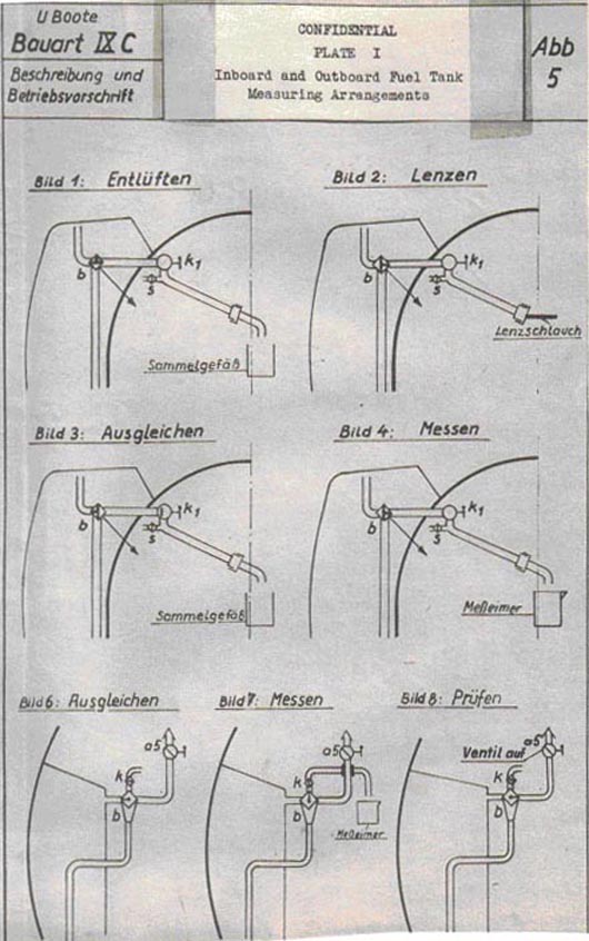
|
|||||
FORMER GERMAN SUBMARINE TYPE IX-C |
|||||
BOILER FEED-WATER EQUIPMENT |
|||||
SUMMARY |
|||||
| This section is inapplicable and the page is inserted only for record purposes. | |||||
July, 1946 |
|||||
PORTSMOUTH NAVAL SHIPYARD, PORTSMOUTH, N. H. |
|||||
- 1 - |
|||||
|
|||||
FORMER GERMAN SUBMARINE TYPE IX-C |
|||||
DISTILLING PLANT |
|||||
SUMMARY |
|||||
| Facilities for the manufacture and stowage of distilled water on the IX-C vessels are considered most inadequate. One distilling unit, with a designed rating of 63.5 gallons per day, supplies all replacement battery water and fresh water for drinking or washing purposes. The total batter water stowage capacity is limited to 160 gallons. | |||||
| The distiller functions on a vapor compression cycle with vaporization taking place under a small vacuum | |||||
June, 1946 |
|||||
PORTSMOUTH NAVAL SHIPYARD, PORTSMOUTH, N. H. |
|||||
- 1 - |
|||||
9C-S58 |
||
C O N F I D E N T I A L |
||
DISTILLING PLANT |
||
| 1. Introduction | ||
| This section will cover the formation of the distillate and its distribution to the battery water tanks and fresh water "distribution" tank. The drinking water system is covered under the S36 section in the IX-C report. | ||
| 2. General Description | ||
| One small low-capacity distiller is installed in the maneuvering room on the IX-C for supplying the ship with its drinking and battery power. The distilled water formed is pumped from the main distillate tank by a hand pump to a gravity feed distillate tank in the overhead from where it is distributed either by a portable hose connection to individual battery water tanks, direct to No. 1 drinking water tank, or via a special filter, to "harden" the water, to No. 1 drinking water tank. | ||
| The still functions in most respects similar to the Kleinschmidt still. A basic difference, however, exists in that evaporation takes place under a vacuum whereas in the U.S. still, it takes place essentially at atmospheric pressure. | ||
| The feed water for the still is supplied to a feed regulating tank from the circulating water main. From here it passes to a feed water level regulator external to the distiller. No pump is needed because of the distiller vacuum The feed enters the distiller at the bottom where it picks up heat from the condensate and brine return coils. A set of electric heating coils is located above a simple baffle arrangement and provides the basic source of heat to the still. Evaporation takes place at approximately 206°F. A positive displacement vacuum pump at the top of the distiller draws in the vapor formed, after it passes over baffles to prevent carry-over, and discharges it at atmospheric pressure to a condenser in the top of the distiller. The heat removed from the vapor thus passes to the salt water feed in the same manor as in the U.S. distiller. The feed water is agitated by a paddle wheel arrangement (geared to the motor drive shaft). The hot condensate then | ||
- 2 - |
||
9C-S58 |
||||||||
| passes through the above-mentioned coils to a small receiver and thence to the distillate tank by gravity. A salinity indicator is at the intake to the distillate tank. A vent and equalizing line runs from the condenser to the receiver and acts to maintain the pump discharge at atmospheric pressure. A vapor bypass is located on the vacuum pump discharge; it is used mainly during starting to reduce the load on the pump as it builds up a vacuum A brine discharge pump, geared to the vacuum pump drive, discharges the brine to the bilge via a regulating valve. A safety valve that lifts between 3.5 to 4.2 psi is fitted to the distiller casing. | ||||||||
| The heating coils installed provide a wide range of heat input to the distiller. The six individual coils have the necessary switching arrangements so that by proper parallel or series setups heat inputs can be varied in steps from .17 KW to 3.36 KW at 110 volts, or .40 KW to 8.00 KW at 170 volts. As a result of the comparatively high heat input possible for such a small unit initial heating of the feed water can be accelerated. During steady operation, only one coil is required to provide the necessary heat. | ||||||||
| The still is in most respects a well-designed and compact unit. All heat exchanger sections are placed within the one shell, thereby limiting the need for much external piping. The condenser, electric coils, and condensate and brine return coils can be readily removed as individual units for servicing. However, no steam trap is provided on the condensate lines so that continued attention must be given to condensate level during operation. | ||||||||
| Test date available shows that this still has attained capacities in excess of the designed rating. On one test approximately 100 gallons/day were produced. | ||||||||
| 3. Individual Components | ||||||||
| a. Distiller (includes heat exchanger) | ||||||||
|
||||||||
- 3 - |
||||||||
9C-S58 |
||||||||||||||||
| b. Tank capacities | ||||||||||||||||
|
||||||||||||||||
| c. Vacuum vapor pump | ||||||||||||||||
|
||||||||||||||||
| 4. Conclusions | ||||||||||||||||
| The capacity of the distilling unit and of the battery water tanks on the IX-C submarine is far below the corresponding U.S. standards for submarines. This results in considerable hardship on the crew during long patrols and necessitates extreme measures to limit battery water consumption. | ||||||||||||||||
| The distiller unit itself is of little exploitation value because of its low capacity. However, its compactness is of merit. By placing all of the elements within the one shell and at the same time making them easily accessible, the designers have provided a unit that requires a minimum of work for its installation and upkeep, and keeps to a minimum the weight and space requirements for the complete installation. | ||||||||||||||||
| A comparison from an output and efficiency standpoint of the two cycles, i.e., the one with vaporization taking place at atmospheric and the other with vaporization taking place under a slight vacuum, can not be readily made because of the many variables associated with the problem. However, it appears that any advantage gained by the requirement for less input heat on the vacuum cycle is lost by the additional power required to compress the greater vapor volume. | ||||||||||||||||
- 4 - |
||||||||||||||||
|
|||||
FORMER GERMAN SUBMARINE TYPE IXC |
|||||
REFRIGERATION |
|||||
SUMMARY |
|||||
| The IXC German Submarine has a limited amount of refrigeration capacity. The only refrigerated space provided is that in the small galley refrigerator. The unit is no larger then a domestic refrigerator, and is not adequate in terms of US vessel practice. | |||||
July, 1946 |
|||||
PORTSMOUTH NAVAL SHIPYARD, PORTSMOUTH, N. H. |
|||||
- 1 - |
|||||
9C-S59 |
||
| 1. General Description | ||
| A comparatively small refrigeration unit is installed on the port side of the pantry. It consists of an icebox normally kept between 35-39°F. and a small ice cuber capable of making 13.2 lbs of ice per day. The compressor, its motor and the condenser are on a common bed plate on top of the ice box. Two sets of cooling coils, one rated at 250 Kg cal/hr (.0826 tons) and the other at 85 KG cals.hr (.0281 tons), are set in series within the ice box. | ||
| The ice box has a wooden frame and is built of sheet metal on the sides, top and bottom and of aluminum on the rear. Aluminum foil and "Torfat" (a granulated cork compound) are used for insulation between the wood and metal. The outside dimensions of the ice box are 41.5 x 51.2 x 53.1 ins. | ||
| Freon is used as the cooling agent in a more or less standard refrigerant cycle. The path of freon through the cycle is as follows: | ||
| 1. Compressed in the compressor | ||
| 2. Cooled and liquefied in an air cooled condenser | ||
| 3. Settles into freon collecting tank | ||
| 4. Passes through freon strainer and h.p. side of a small freon heat exchanger where it is further cooled by the low pressure freon. | ||
| 5. Enters the thermo - controlled expansion valve where it expands to vapor. | ||
| 6. Passes through the largest set of cooling coils and then through a second smaller set. | ||
| 7. Flows through the l.p. side of the freon heat exchanger and then passes to the suction side of the compressor. | ||
| Low and high pressure cut out switches are installed in the compressor motor circuit. The former is activated by the suction pressure at the compressor and the latter by the pressure in the collecting tank. | ||
- 2 - |
||
9C-S59 |
|||||||||||||||||||||||||||
| The units within the circuit are of standard design and in most cases do not represent the latest developments. The compressor has two single acting pistons and is air cooled. A rather complicated shaft seal is used wherein oil pressure greater than the suction pressure of the freon is used to prevent freon leakage out along the shaft. An obsolete type of thermostatically controlled expansion valve is used. Regulation of valve setting is controlled through the medium of expanding bellows, whereas on better designs, diaphragms are used. | |||||||||||||||||||||||||||
| 2. Individual Components | |||||||||||||||||||||||||||
| a. Compressor | |||||||||||||||||||||||||||
|
|||||||||||||||||||||||||||
| b. Cooling Coils | |||||||||||||||||||||||||||
|
|||||||||||||||||||||||||||
| 3. Conclusions | |||||||||||||||||||||||||||
| The refrigeration system on the IXC submarines is not considered adequate for extended patrols. No cold storage box was installed and the capacity of provision stowage ice box is small for the relatively large crew carried on the vessel. The refrigerant cycle is standard in nature and offers nothing of particular interest. | |||||||||||||||||||||||||||
- 3 - |
|||||||||||||||||||||||||||
|
|||||
FORMER GERMAN SUBMARINE TYPE IX C |
|||||
ELECTRICAL SYSTEM - GENERAL |
|||||
SUMMARY |
|||||
| The electrical plant follows conventional German submarine practice with storage batteries, main electric machines usable as either motors or generators, electrically operated auxiliaries and accompanying controls and distribution systems. In general, most equipments are compact and designed to be accessible for maintenance, although in some cases the location in the vessel interfered with accessibility. Greater temperature rises appear to be permitted then is current USN practice. Efforts to conserve copper and other critical materials were evidenced. | |||||
March, 1946 |
|||||
PORTSMOUTH NAVAL SHIPYARD, PORTSMOUTH, N. H. |
|||||
- 1 - |
|||||
9C-S60 |
||||||||||||||||||
TABLE OF CONTENTS |
||||||||||||||||||
|
||||||||||||||||||
- 2 - |
||||||||||||||||||
9C-S60 |
||
C O N F I D E N T I A L |
||
ELECTRICAL SYSTEM - GENERAL |
||
| A. Descriptive | ||
| (a) Introduction | ||
| This report of the electrical system is written to present in a general way the type of system installed, its employment, and methods of distribution as well as some of the characteristics of the auxiliary power equipment. For detailed information regarding these components reference should be made to the applicable detail reports. | ||
| (b) Description | ||
| This type of vessel is provided with two main double armature electric machines, one port and one starboard, which can be mechanically and electrically connected for use either as motors for the ship's propulsion or for use as generators for charging the batteries. | ||
| Split main cubicles are installed, one port and one starboard, for the control of the main power. These cubicles can be isolated from the batteries by means of double pole air circuit breakers. | ||
| Two batteries are provided, one forward (No. 2) and one aft (No. 1). These are German type 44MAL740 each consisting of 62 cells. The cells are of the pasted plate type designed for a "life" of 15 to 21 months. Neither individual cell voltmeters nor hydrogen detectors are installed. Switching arrangements provide for use of the batteries individually, in series, or in parallel. Voltage variations between 110 to 170 and 220 to 340 are possible. | ||
| Auxiliary power requirements can be selected from either battery or can be divided between both batteries. Auxiliary machinery operates from voltages of 110 to 170. Two auxiliary power switchboards are provided on which the auxiliary machinery circuits are connected. Individual circuit switches are not generally provided on these boards, the circuits being fused only. | ||
| Regulated 110 V DC for purposes listed below is obtained through the use of voltage sensitive relay actuated regulators. | ||
- 3 - |
||
9C-S60 |
||
| (1) Ship's Illumination. | ||
| (2) Dial Light Illumination. | ||
| (3) I.C. Transmitter-Indicator Systems. | ||
| (4) I.C. Hull Opening & Vent Valve Indicating Systems. | ||
| (5) Control Circuits for Motor Generators. | ||
| (6) Electronic Equipments as required. | ||
| (7) Standby Torpedo Charging Power Supply. | ||
| (8) Running & Signal Lights. | ||
| Controllers for motors and motor generators are generally located adjacent to the unit to be controlled. Manual starters are used in most applications. These provide for across the line starting, resistance starting and for starting series field connected windings. Magnetic controllers are only employed for motor generators, steering and hydraulic pump motors. | ||
| Interior Communication Circuits, Fire Control Circuits and A.C. motor generator control circuits are not grouped to be controlled from common switchboards as is generally done in USN practice. | ||
| A common fused board located in the Radio Room provides for the distribution of A.C. power and 110 V. regulated D.C. power for the electronic equipment. The A.C. power requirements are not as great in this system primarily because most I.C. equipment is designed to operated on 110 Volt D.C. and the electronic installation is not as extensive as in present USN submarines. | ||
| Cable and lead designations in the form of cable tags and stamped terminals or fibre tags are not as widely used or required as in present USN practice. See report 2G-9C-S28 for detailed information. | ||
| Practically all cable is provided with synthetic rubber insulation around which is woven a protective metal covering. For a given cross section current densities are generally greater than is present in USN practice. | ||
| Common stuffing boxes are used for cable banks passing through water-tight bulkheads, as many as forty to fifty cables including main power cables are led through one stuffing box. | ||
| Methods employed for supporting cable banks and cable entrances to equipments are somewhat similar to methods currently being used on USN submarines. Circular rubber packing of rectangular cross section not | ||
- 4 - |
||
9C-S60 |
||
| vulcanized to the cable is used in tube terminals and stuffing tubes. | ||
| Captive screws are used extensively on covers, subassemblies, and other components in all systems. | ||
| The trend of German design particularly in I.C., F.C. and electronic equipment is to have the components of the various equipments so constructed that they may be readily removed for replacement or maintenance without disconnecting the system wiring. Considerable emphasis is placed on designs that minimize the possibility of incorrect assembly. | ||
| In general, electrical clearances and insulation are considered as being inferior to present USN requirements. | ||
| The design contemplates use of electrical energy for the following purposes: | ||
| a. Submerged propulsion, except when snorkeling | ||
| b. Surface propulsion in emergency | ||
| c. Steering and depth control | ||
| d. Ship's heating and ventilating | ||
| e. All pumps excepting fresh water | ||
| f. Fresh water stills | ||
| g. Torpedo heating and charging | ||
| h. Galley equipment | ||
| i. Galley refrigerator | ||
| j. Motor generators to provide A.C. power for various purposes | ||
| k. Air compressor (Note there is in addition a Diesel air compressor installed) | ||
| l. Ship's lighting | ||
| m. Interior communication equipments | ||
| n. Signalling and indicating systems, telegraphs, and gyro compass | ||
| (c) Conclusions | ||
| The overall design of the electric plant installed in this type vessel reflected the German need to conserve labor and material and additionally to have systems and methods that were readily adaptable for mass production of submarines to an extent that only the barest essentials with regard to present USN operating doctrine are incorporated in his systems, thus placing increased responsibility upon operating personnel for the successful operation of these plants. | ||
- 5 - |
||
9C-S60 |
||
| The above considerations required the acceptance of practices in design and installations not presently acceptable to USN designers. | ||
| The simplicity of the installations and the German method of presentation is such that operating personnel can readily become acquainted with all phases of the installation. | ||
| Interrogation of USN personnel who operated and are operating this type electrical installation indicates that electrical maintenance is negligible and that the equipments operate satisfactorily. | ||
- 6 - |
||
|
|||||
FORMER GERMAN SUBMARINE TYPE IX C |
|||||
AUXILIARY GENERATORS |
|||||
NOTE: |
|||||
| See Section S63 for discussion of generators. No auxiliary generators were provided on this type of vessel. | |||||
March, 1946 |
|||||
PORTSMOUTH NAVAL SHIPYARD, PORTSMOUTH, N. H. |
|||||
- 1 - |
|||||
|
|||||
FORMER GERMAN SUBMARINE TYPE IX C |
|||||
ELECTRIC POWER DISTRIBUTION |
|||||
SUMMARY |
|||||
| In general, the auxiliary power distribution circuit layout installed in Type IX-C vessels corresponds with the present USN system. However, the application of protective, switching and isolating components making up these circuits differs appreciably from current USN practices. Creepage clearances and insulation values are at lower levels. External shock protection is more widely employed. | |||||
| Individual cases of particularly good and bad workmanship and design are evidenced throughout the system although the installations are reasonably uniform with respect to German practices. | |||||
March, 1946 |
|||||
PORTSMOUTH NAVAL SHIPYARD, PORTSMOUTH, N. H. |
|||||
- 1 - |
|||||
9C-S62 |
||||||||||||||||||||||||||||||||||
TABLE OF CONTENTS |
||||||||||||||||||||||||||||||||||
|
||||||||||||||||||||||||||||||||||
- 2 - |
||||||||||||||||||||||||||||||||||
9C-S62 |
||
| A. DESCRIPTIVE | ||
| (a) Introduction | ||
| The scope of this report is to present the type of auxiliary power distribution circuits employed and the components installed in those circuits on type IX-C vessels. In order that the report may be more effectively utilized, it is divided into the various subgroups, S62-1, S62-2, S62-3, and S62-4, in conformance with the Navy Filing Manual. Each subgroup is written as a separate report and incorporated as an integral part of the overall S62 group. | ||
| For detail information regarding the circuit layout with regard to the compartmentation localization of the various components reference should be made to the German Instruction Book "Skizzenbuch für die Maschinenmannsachaft für U-Boote Typ IX-C40, Band E, Allgemeine E Anlagen" (Sketch book for the Machinery for U-boats Type IX-C40, Volume E, General-Electrical Systems). | ||
| (b) Description | ||
| The auxiliary power distribution system installed in Type IX-C vessels corresponds in general to current USN system layout with the following noted exceptions: | ||
| (1) Instead of using a bus tie switch mounted on the after switchboard to provide for connecting both switchboards to the same battery, the German uses separate transfer switches, one for each switchboard to provide for connecting the switchboard to the desired battery. Both of these transfer switchboards are located in the control room, which is considered a poor practice due to the fact that a casualty in the control room jeopardizes the safety of the entire vessel since a possibility of losing all auxiliary power exists. | ||
| (2) Air circuit breakers are not used in any auxiliary power circuits for protective devices. | ||
| (3) The auxiliary power load is connected to the batteries ahead of the battery breaker. Disconnect switches are not provided, the circuits being fused only. Since the total auxiliary load can be connected to one battery, the protective value of the fuse is rather dubious when operating under normal conditions of auxiliary load being divided between both batteries. | ||
| (4) Feeder circuits at the distribution boards are not provided with disconnect switches, the circuits | ||
- 3 - |
||
9C-S62 |
||
| being fused only. These circuits usually feed branch distribution boxes which in turn are fused to protect the given auxiliary equipment. Disconnect switches are not installed in the branch distribution boxes. | ||
| (5) Creepage clearances between polarities and ground and polarity are frequently found to be 50% of the required values for comparable USN design. | ||
| (6) External shock mounting in form of bonded rubber mounts used in compression, tension, and shear are employed throughout on the various components. It is possible that this secondary means of shock protection was employed so extensively because of the Germans' inability to develop high shock components to the satisfactory level attained by USN designers. | ||
| (c) Conclusions | ||
| There is nothing to recommend complete adoption of the German distribution system installed in this type vessel for installation in American submarines. USN specifications require an installation engineered at a much higher level with respect to circuit protective devices and safety of the vessel as a whole. | ||
- 4 - |
||
|
|||||
FORMER GERMAN SUBMARINE TYPE IXC |
|||||
SWITCHBOARDS |
|||||
SUMMARY |
|||||
| The switchboards installed in this type vessel are of rigid self-supporting construction providing only a minimum of equipment with respect to circuit design. The individual feeder circuits are not provided with disconnect switches but are fused only. Neither Interior Communication or Fire Control Circuits are grouped to be controlled from common switchboards. | |||||
March, 1946 |
|||||
PORTSMOUTH NAVAL SHIPYARD, PORTSMOUTH, N. H. |
|||||
- 5 - |
|||||
9C-S62-1 |
||||||||||||||||||
TABLE OF CONTENTS |
||||||||||||||||||
|
||||||||||||||||||
- 6 - |
||||||||||||||||||
9C-S62-1 |
||
| A. DESCRIPTIVE | ||
| (a) Introduction | ||
| The scope of this report is to present in a concise manner, the German practices incorporated in the construction of the auxiliary power switchboards. For detailed information regarding construction and circuit details. reference should ben made to the German Instruction Books, "Beschreibung und Betriebvorschrift für E-Maschinen, Haupt und Hilfschalttafeln", (Descriptive and Operational Data for the Electric Machines, Main and Auxiliary Switchboards), and to the applicable detail reports on the various components. | ||
| (b) Description | ||
| The voltages controlled by these switchboards are 110-170 V. D.C. for main and auxiliary power and regulated 110 V. D.C. for ship's lighting, I.C. equipment and various other purposes. The number of panels incorporated in a board varies depending upon its function. | ||
| The switchboards are of rigid, self-supporting angle iron and flat bar arc welded construction, hinged and bolted front and top covers, bolted perforated sheet steel side and rear covers. The hinges are of continuous Veeder Root design (Piano hinge). No attempt is made to isolate the various sections, bus, fuse, metering, etc. from each other. The units are drip-proof and are designed for natural ventilation. Supply and distribution leads are generally led in either the top or bottom at the rear of the units. The switchboards are mounted on bonded rubber mounts in compression for shock protection. Components are readily accessible and removable from the structure. No effort has been made to keep resistor units as high in the structure as possible to minimize the heating effect on other components. Circuits do not appear to be segregated into vital and non-vital classifications and identification of cable and circuits is kept to the minimum consistent with the German method of presenting the systems to the operating personnel. (The German method of presenting the various systems will be discussed in detail in Report 2G-9C-S28 on Type IXC vessels). | ||
| Ammeters and voltmeters are provided for measuring the input current and voltage of the 110-170 V panels and for measuring the output voltage and current of the voltage sensitive relay actuated regulator provided for | ||
- 7 - |
||
9C-S62-1 |
||
| the regulated 110 V D.C. There is no provision made for using the installed voltmeter to check ground voltages. Controllers in the main control switchboard are manually operated being provided with levers for vertical motion. Controllers are mounted directly behind the front panel. Socket type, porcelain body, sand filled fuses with blown fuse indicators are used throughout. Tube type terminals soldered to the cables are bolted to terminal board or buses as required. Riser buses are installed on either side at the rear of the structures to which the individual feeder circuits are connected either by cables or by copper bars. A thin coat of red glyptol-like paint is applied to the copper bars to minimize corrosion. Application of silver painted contact surfaces is sporadic. Insulating materials are kept to a bare minimum, none of which appears to be molded to the copper bars. | ||
| Inspection of the bus work indicates that labor was considered secondary to copper conservation as is evidenced by the following example. | ||
| Where the cross sectional area and geometry of a connection bar for a given maximum current did not permit drilling for the desired size connection bolt and still provide sufficient surface contact, the Germans frequently welded "ears" to the bar on both sides at each end in way of the contact area. | ||
| In general, greater current densities are permitted for bus and connection bars and cables than is current USN practice. | ||
| Neither I.C. nor Fire Control Circuits are grouped to be energized at common switchboards. Considerable disadvantage occurs from this practice in that if in the control room the operating personnel are in a hurry to perform their various duties, there would be a tendency to get in each other's way in moving about to actuate the I.C. and F.C. circuits. | ||
| (c) Conclusions | ||
| The German need for economy in labor and critical materials is reflected in the design and manufacture of these switchboards. There is nothing of interest in the structures as a whole. The salient features of the various components will be discussed in detail under the applicable "S" group reports. | ||
- 8 - |
||
|
|||||
FORMER GERMAN SUBMARINE TYPE IXC |
|||||
WIRE AND WIRING APPLICANCES |
|||||
SUMMARY |
|||||
| The German installation of wire and wiring appliances reflect the need for conserving labor and material to an extent that in many applications his standards are well below USN requirements. In many cases it would appear that standards are lowered in order to adopt mass production methods. | |||||
June, 1946 |
|||||
PORTSMOUTH NAVAL SHIPYARD, PORTSMOUTH, N. H. |
|||||
- 9 - |
|||||
9C-S62-2 |
|||||||||||||||||||||||||||||||||||||||||||||||||||||||||||||||||||||||||||||||||||||||||||||||||||||||||||
TABLE OF CONTENTS |
|||||||||||||||||||||||||||||||||||||||||||||||||||||||||||||||||||||||||||||||||||||||||||||||||||||||||||
|
|||||||||||||||||||||||||||||||||||||||||||||||||||||||||||||||||||||||||||||||||||||||||||||||||||||||||||
- 10 - |
|||||||||||||||||||||||||||||||||||||||||||||||||||||||||||||||||||||||||||||||||||||||||||||||||||||||||||
9C-S62-2 |
||
| A. Introduction | ||
| The scope of this report is to present in a general manner the German practices observed in type IXC vessels. | ||
| Individual components have been shipped to the Bureau of Ships, Code 660, Washington D.C. for detailed exploitation and reference should be made to their reports when they become available. These components are listed below. | ||
| 1. Main Battery Air Circuit Breaker. | ||
| 2. Lighting Voltage Regulators. | ||
| 3. Watertight receptacles and Plugs. | ||
| 4. Rotary Type Snap Switches (to 600 A. capacity). | ||
| 5. Fuses and Fuse Retainers. | ||
| 6. Torpedo Charging Panel with associated equipment including motor-generator with controls. | ||
| 7. Torpedo Heating Panel with associated equipment. | ||
| In addition considerable information may be obtained from the German instruction book "Grundzuge für Electriche Unlagen - Berlin 1940 - Oberkommando der Kriegsmarine" (Outline for electrical Systems - Berlin 1940 - Navy High Command). | ||
| A separate section in this book is devoted to practices to be followed for submarine installations in which may be found discussions of the following subjects. | ||
| 1. Fundamental definitions. | ||
| 2. Tests for motors, generators and transformers. | ||
| 3. Practices with regard to sound silencing equipments including design concepts. | ||
| 4. Cable descriptions and ratings including one hour ratings. | ||
| 5. Fuse size application. | ||
| 6. Miscellaneous other information with regard to practically all electrical shipboard installations. | ||
| B. Descriptive | ||
| I. General | ||
| The German installation in this type vessel reflects the German need for economy of labor and material. Standards are lowered to attain these ends. | ||
- 11 - |
||
9C-S62-2 |
||
| To amplify the above the following illustrations are presented. | ||
| (a) Cables of a given cross section are given two ratings - one for continuous duty and a one hour rating. The latter being 50% more than the continuous duty rating. | ||
| (b) In order to take labor saving advantage of a community stuffing box and its inadequate methods of sealing for passing cables thru watertight bulkheads, the German lowered his compartment air test from 15 pounds to 3 pounds. | ||
| II. Air Circuit Breakers | ||
| For detailed information with regard to Breakers and Controllers reference should be made to the German Instruction Book "E. Maschinen Haupt und Hilfsschalttafeln" (Electric Machinery - Main and Auxiliary Switchboards) which contains a detail description of the various breakers and contactors employed including pictures and detail drawings of the operating mechanism. | ||
| In addition, a circuit breaker has been shipped to the Bureau of Ships, Code 660 for detailed exploitation. | ||
| Observations at the Shipyard indicate that contactors and breakers are not as well designed as USN breakers and contactors both as to space and weight and to operating mechanism design. Electrically operated breakers or contactors are not installed, the majority being manually operated although provision is made for tripping battery breakers from the Maneuvering Room. A voltage coil is employed for this purpose. | ||
| III. Conduit | ||
| Galvanized steel piping is used for conduit in the few applications made by the German. These conduits are installed in circuits led from the Conning Tower to the Bridge. Cone type fittings are used with the conduit. | ||
| IV. Controllers | ||
| Controllers are discussed in detail in Report 2G-9C-S63. | ||
| V. Distribution Boxes | ||
| The German distribution boxes are of no better design than present USN designs and in most cases would | ||
- 12 - |
||
9C-S62-2 |
||
| not meet USN requirements. | ||
| Designs vary to incorporate watertight, non watertight, and drip-proof features. | ||
| Housings and covers are either cast or fabricated from sheet metal. When cast, tube terminals are cast integral with the housing. | ||
| Socket type rubber gaskets of rectangular cross section are used in watertight designs. Captive screws are used thru out. | ||
| Quick opening fuse and distribution boxes are widely used. In design these are somewhat similar to those used by USN in the V class submarines. | ||
| VI. Fuses and Fuse Retainers | ||
| A description and drawings of German fuse design may be found on pages 9, 10, and 11 of German Instruction Book "Funklehrbuch der Marinenachrichtenschule, Teil I" (Radio Instruction Book - Naval Communication School Part 1.) | ||
| The fuse and fuse retainer shown on page 10 of the above reference is used in ninety percent of the applications. These fuses are designed in various desired capacities from 6 to 600 amperes. The practice employed is to use up to five different ratings in one size fuse body. For example, two, fifteen, and twenty ampere capacity fuses are mounted in a fuse body of the same size, hence one size retainer is required for fuses of those capacities. However, in order to minimize the possibility of misapplication, the fuse retainer is provided with a small phenolic washer at the bottom. For each different fuse rating in that particular body size, the diameter of the hole in the washer differs to mate with the diameter of the pin cap at the bottom of the fuse. | ||
| The pin cap also serves as one contact of the fuse to which the fuse element is secured. The top of the fuse is provided with a larger cap which is cemented to the fuze body. Thus the fuse element is secured between the two caps. In addition, provision is made for blown fuse indication. In the larger sizes an additional small wire is secured to the lower cap and to a small colored cap which seats in the upper cap, when the fuse blows the colored | ||
- 13 - |
||
9C-S62-2 |
||
| cap falls from its seat. The colors differ for each fuse size to provide means for ready identification of the fuse size. | ||
| The main weakness of the German fuses lies in the use of porcelain for the body, due to its inability to withstand high-impact shock. | ||
| The threaded ferrule on the fuse retainer cap is serrated to minimize the possibility of its becoming lose due to vibrational disturbances. | ||
| External shock mounting is not employed. | ||
| Fuses and fuse retainers of this type offer interesting possibilities for further development, particularly with regard to their space requirements. Several have been shipped to the Bureau of Ships, Code 660 with the battery breaker for detailed exploitation and reference should be made to their report when it becomes available. | ||
| VII. Insulating Materials | ||
| Materials for insulation are of the usual types varying from friction tape to molded bakelite products. Observations made at the Shipyard indicate that the German had not advanced as far in this field as had the USN. The German limited his application to relatively small parts, due primarily to his apparent inability to develop high shock insulating material. | ||
| "Melemine" or its equivalent has not been observed. | ||
| VIII. Rheostats | ||
| Rheostats exist in various sizes and shapes, most of which are similar in design to present USN designs with the exception that porcelain is used extensively as an insulating material with its inherently weak shock characteristics. | ||
| A voltage regulator has been shipped to the Bureau of Ships, Code 660 for detailed exploitation, and reference should be made to their report when it becomes available with regard to the characteristics of German resistor wire. | ||
| IX. Stuffing and Terminal Tubes | ||
| (a) Tube terminals. | ||
- 14 - |
||
9C-S62-2 |
||
| German tube terminal designs are similar to USN design, the major difference being in the packing seat. The German seat is normal to the cable as contrasted with USN practice of having the packing seat at 45° to the cable. | ||
| The German packing consists of a single circular rubber washer of rectangular cross section. (Rubber insulation is used extensively in German cables). | ||
| Tube body, washers and gland nuts are plated steel. Provision is made in the gland nut on three surfaces of the hexagon shaped nut for small screws, one of which is used for grounding the armour of the cable. | ||
| Where portable cables are used, a phenolic gland nut is substituted for the steel gland nut. Otherwise the practice is the same. | ||
| (b) Stuffing Tubes | ||
| The German method of taking cable banks through watertight bulkheads is to use a community stuffing box. Banks containing up to sixty cables, including main power, are passed thru the bulkhead in this manner. | ||
| Its weakness lies in the fact that due to the interstices of the armor on the cable it is not possible to obtain a uniformly solid mass in way of the stuffing box, thus increasing the difficulties in obtaining a satisfactory compartment air test. | ||
| In those cases where individual cables leave the pressure hull, stuffing tubes somewhat similar in design to USN stuffing tubes are employed. The major difference is in the length of the tube which is greater due to the German's inability to attain a satisfactory pressure proof cable entrance. | ||
| German practice in this case is to use armoured cable which is run thru conduit on the outboard side. | ||
- 15 - |
||
9C-S62-2 |
||
| The sealing is installed on the inboard side of the stuffing tube. It consists of pouring about 1-1/2" depth of sealing compound which is backed up by a standard circular rubber washer, a gland washer and finally the gland nut. | ||
| On the outboard side the conduit is welded to the stuffing tube. | ||
| On each stuffing tube of this type, a separate drain line and petcock is installed in such manner that it it outboard of the packing but it is located within the vessel. This provides a means for checking the integrity of the conduit fittings. | ||
| In the several cases where coaxial cables are run thru watertight bulkheads or the pressure hull, shear valves are employed. These are rather elaborate affairs requiring two wrenches to be stowed near them for actuating the valve. They can be operated from one side only, hence their value in watertight bulkheads is dubious. | ||
| Two designs are used, one for single cables, the cutting edge of which operates as a petcock, the other a three cable unit, the cutting edge of which operates as a rotary knife. | ||
| X. Individual Switches | ||
| By far and large, the German preferred rotary type switches. These are found in capacities up to 600 amperes. | ||
| Simple spring and star wheel (spring loaded) operating mechanisms are used extensively. | ||
| In the smaller sizes, the German parts, except for the operating mechanism, are interchangeable with corresponding parts on USN switches. The major difference being in the ratings given the switches, the German being 250 V 10 Amps D.C. USN rating being 250 V, 5 Amps D.C. The above USN switch is plan No. 9-S-4718. | ||
| Life tests made on the above German switch resulted in mechanism failure of the spring after an average of 12,475 cycles as compared with USN requirements of 37,500 cycles. | ||
- 16 - |
||
9C-S62-2 |
||||||||
| In addition, rotary type switches of the following ampere capacities have been shipped to the Bureau of Ships, Code 660 for details exploitation and reference should be made to their reports when they become available. | ||||||||
|
||||||||
| XI. Voltage Regulators | ||||||||
| Two regulators are installed to obtain regulated 110 V D.C. from a variable power supply of 110 to 170 V. D.C. | ||||||||
| Provision is made for manual and automatic operation. A voltage sensitive relay controls two relays, which in turn control the direction of current flow in the armature of the drive motor. The unit is similar to USN regulators currently being installed in submarines, being of approximately the same KW output. | ||||||||
| For information with regard to its installation, reference should be made to report 2G-9C-S61. | ||||||||
| In addition a voltage regulator has been shipped to the Bureau of Ships, Code 660 for detailed exploitation and reference should be made to their report when it becomes available. | ||||||||
| XII. Watertight Receptacles and Plugs | ||||||||
| The German design W.T receptacle and plug consists of a molded phenolic housing in which the necessary metal inserts are provided for securing the covers. Tube terminals are moulded integral with the housing. | ||||||||
| Phenolic gland nuts and circular rubber washers of rectangular cross section are employed in the tube terminal. A separate ground strap is mounted on the bottom of the housing to which the cable armor is grounded. | ||||||||
| Suitable rubber gaskets are employed in way of the cover to obtain watertight integrity. | ||||||||
| The standard German rotary snap switch is employed in the housing. | ||||||||
- 17 - |
||||||||
9C-S62-2 |
||
| The receptacle consists of an assembly of porcelain and brass parts. Polarization is obtained by rotating the grooved contacts as desired, then locking them in position. The use of porcelain is considered poor due to its shock characteristics. | ||
| Watertight receptacles and plugs have been shipped to the Bureau of Ships, Code 660 for detailed exploitation and reference should be made to their report when it becomes available. | ||
| XIII. Wire and Cable | ||
| German cables exist in various sizes and number of conductors, both armour, shielded, and portable. In nearly all cases rubber or synthetic rubber is used for insulation of the individual conductor and for the outer sheath. | ||
| All the rubber type insulation burns readily, thus minimizing any interest in German cables. | ||
| It would appear that standard methods of manufacture are employed. However, it is presumed that detail information may be found in Nav Tech Report No. 78-45 of April 1945. This report is not available in the Shipyard. | ||
| Detail information with regard to cable type and application is contained in the German instruction book references in the introduction. | ||
| The German practice of assigning one hour ratings to cables os an indication of his desire to conserve critical materials, and is worthy of consideration for war use particularly, in view of the fact that copper shortages forced electrical manufacturers to resort to copper plated steel for current carrying parts in many applications with its attendant increase in labour required for manufacture. | ||
| A description of a German watertight cable is contained in Report 2G-9C-S68. It is used in conjunction with underwater sound installations and is the only cable of its type observed. | ||
| XIV. Wiring & Wiring Appliances for Switchboards and Power Leads | ||
| The German application of wiring and wiring appliances is of simple design and in many cases considerably inferior to USN specification for comparable installations. German practices include the following: | ||
- 18 - |
||
9C-S62-2 |
||
| (a) Soldered Terminals on larger cables. | ||
| (b) No attempt made to seal the cable insulation at the terminal entrance. | ||
| (c) Slotted stud with cap type screws securing the connection to the bottom of the slot. These studs are usually assembled on porcelain bases in form of terminal boards. | ||
| (d) No wiring troughs are employed to protect and facilitate switchboard wiring. | ||
| (e) Leads connecting stationary components to instruments on hinged panels are run directly with a loop formed at the hinged side as contrasted with USN practice of using double sets of terminal blocks. | ||
| (f) Wire used in switchboard installation is provided with rubber insulation which does not have heat and flame characteristics. | ||
| (g) A minimum of hardware such as jam nuts, lock washers, flat washers is used thus increasing the possibility of losing the continuity of the circuit due to vibrational disturbances. | ||
| XV. Hangers | ||
| The German design with regard to cable hangars is somewhat similar to USN designs. The major differences lie in the fact that his hanger straps are generally thirty percent lighter in gauge and are usually spaced 10 to 25% further apart than required by USN specifications. | ||
| In most cases, except for main power cable banks his installations are similar to those shown as A2 on sheet 3 of 9-S-3980, Alt. 25 with the following exceptions. The step hanger is tapped for 1/4" screws, round head screws are used in these holes to secure the strap hanger to the hanger support. Jam nuts, lock or safety washers are not used to minimize the possibility of the strap becoming loose due to vibrational disturbances. | ||
| In main power cable banks which were run with auxiliary power and I.C. cable banks, the hangers are similar to that shown on Sheet 12 drawing 9-S-3980, Alt. 25 with the following exceptions. | ||
- 19 - |
||
9C-S62-2 |
||
| (a) Piece X stiffener is not used. | ||
| (b) The dimension from the step hanger to the hull is usually 2-1/2" rather than the 3/4" used in USN practice. | ||
| (c) 1/4" round head screws in tapped holes secure the strap hangar to the step hanger. | ||
| In all cases strap hangers are formed to suit the cable lay. Workmanship observed indicated that the forming was done at the cable lay rather then in the shop as is USN practice. | ||
| Arc welding is employed to secure cable hangers to the hull. Zinc chromate was applied to the step hanger and weld to minimize corrosion. Strap hangers are all galvanized for corrosion protection. | ||
| The effectiveness of the above corrosion protection is dubious. Observation of cable supports in way of compartments in which plastic sheathing is employed for drip proof protection indicates that considerable corrosion was occurring due either to lack of application or the quality of the materials used. | ||
| Resistance or arc welded studs are not employed. | ||
| XVI. Ship's Electric Heater Units | ||
| These units of 750 and 1000 watt capacities are portable radiant type heaters made from suitably formed sheet metal to which aluminum paint had been applied. They corroded readily and are considered very inefficient for the purpose intended. The power supply is obtained from the battery at 110 to 170 volts D.C. | ||
| For detailed information reference should be made to the German Instruction Book "Beschreibung und Betriebvorschrift für die Kuhlanlage Eletrische Kocheinrichtung auf U-805. (Description and Operating Instructions for the Refrigerant and Cooking Equipment on U-805). | ||
| These heaters were not returned to the vessels after overhaul but were replaced with suitable USN heaters. | ||
- 20 - |
||
9C-S62-2 |
||
| XVII. Ship's Galley Equipment | ||
| There is nothing unique or desirable about the galley equipment. It has been removed during overhaul of the vessel and replaced with USN equipment. | ||
| For detailed information reference should be made to the German Instruction Book. "Beschreibung und Bertriebvorschrift für die Kuhlanlage Electrische Kocheinrichtung" (Description and Operating Instructions for the Refrigerant and Cooking Equipment on U-805). | ||
| C. Conclusions | ||
| The German installations described herein reflect the German need to conserve material and labor and in general may be considered inferior to comparable USN installations. The exceptions to this may be determined from the reports on individual components as they become available from the Bureau of Ships, Code 660. | ||
- 21 - |
||
|
|||||
FORMER GERMAN SUBMARINE TYPE IX-C |
|||||
BATTERIES (ELECTRIC POWER DISTRIBUTION) |
|||||
NOTE |
|||||
| Batteries other than the main storage batteries are not employed for electric power distribution in German submarines. | |||||
| Dry cells are used for various purposes such as portable radio receivers, flash lights, etc. These cells are simpler in shape, size, and design to those available commercially in U.S. Voltages observed are 1, 5, 3, 6, 45, 90 and 120. | |||||
| Wet cell batteries are used in the following circuits: | |||||
| (1) The resistance thermometer with the main motor bearing temperatures. This battery is a six volt battery designed and constructed much the same as U.S. automobile batteries. | |||||
| (2) The emergency lighting circuit employs a 4.5 volt wet cell at each lighting fixture. Several of these cells have been sent to BuShips, Code 660 for detailed exploitation, and reference should be made to their report when it becomes available. | |||||
| A small constant potential battery charging panel is installed for charging the above batteries. There is nothing unique in its construction or design. This panel is also used for charging torpedo batteries which have been removed from the torpedo thus serving as a standby | |||||
- 22 - |
|||||
|
|||||
| torpedo charging panel and additionally for charging batteries of torpedoes not stowed in the torpedo rooms. | |||||
July, 1946 |
|||||
PORTSMOUTH NAVAL SHIPYARD, PORTSMOUTH, N. H. |
|||||
- 23 - |
|||||
|
|||||
FORMER GERMAN SUBMARINE TYPE IXC |
|||||
BATTERIES, STORAGE, SUBMARINE PROPELLING |
|||||
NOTE |
|||||
| The German battery, type 44MAL740, installed in this class vessel has been the subject of special interest by the Bureau of Ships, Code 660s and the Nav Tech Mission Europe. | |||||
| At the direction of the Bureau cells of this type have been shipped to various Naval and commercial activities for detailed exploitation. Report have not been received by the Shipyard for incorporation in this report, however, it is expected that detailed reports will be forwarded to the Bureau of Ships and reference should be made to them when they become available. The following activities have been studying these batteries. | |||||
| Bureau of Ships, Code 660s | |||||
| Naval Research Laboratory, Anacostia, D.C. | |||||
| Material Laboratory, New York Naval Shipyard | |||||
| Exide Storage Battery Company | |||||
| National Storage Battery Company | |||||
| In addition it is understood that Nav Tech Report 210-45 of August 1945 pertains to German batteries of various types, their construction and methods employed in their manufacture. This report is not available in the shipyard. | |||||
| The German practice with regard to battery installation is discussed in detail in Nav Tech Report 310-45 of August 1945. | |||||
| In addition German Instruction Books listed below contain considerable information with regard to installation and operation of these batteries: | |||||
| (a) Beschreibung und Betriebvorschrift für die Akkumulatoranlage. (Description and Operation for the Battery system). | |||||
- 24 - |
|||||
9C-S62-4 |
||
| (b) Beschriebung und Betriebvorschrift der Batterie U Boote Type IXC (Description and OPerating Instructions of the Battery Submarines Type IXC). | ||
| (c) Beschriebung und Betriebvorschrift der Batterie auf U Booten Bauart IXD1 und 2. (Description and Operating Instructions for the Battery of Submarine Types IXD1 and 2). | ||
July, 1946 |
||
PORTSMOUTH NAVAL SHIPYARD, PORTSMOUTH, N. H. |
||
- 25 - |
||
|
|||||
FORMER GERMAN SUBMARINE TYPE IX-C |
|||||
MOTORS AND CONTROLLERS |
|||||
SUMMARY |
|||||
| The German application of auxiliary motors and their associated controls is of rugged and simple design which requires increased responsibility on the part of ship's personnel for starting and operating his equipments. | |||||
| Simple compact manual controllers are used extensively for motors regardless of size. Magnetic controllers are seldom employed. | |||||
| The German motors are of the usual D.C. types normally found in U.S.N. Submarines, being compact and light in unit weights. | |||||
| A novel feature of motor design with regard to U.S.N. submarine practices past and present incorporates the use of a series starting field for minimizing inrush currents rather than external starting resistors and their associated accelerating relays as is present U.S.N. practice in submarines. | |||||
| External shock mounting in form of bonded rubber mounts both in compression and shear was used extensively | |||||
May, 1946 |
|||||
PORTSMOUTH NAVAL SHIPYARD, PORTSMOUTH, N. H. |
|||||
- 1 - |
|||||
9C-S63 |
|||||||||||||||||||||||||||||||||||||||||||||||
TABLE OF CONTENTS |
|||||||||||||||||||||||||||||||||||||||||||||||
|
|||||||||||||||||||||||||||||||||||||||||||||||
- 1a - |
|||||||||||||||||||||||||||||||||||||||||||||||
9C-S63 |
||
C O N F I D E N T I A L |
||
AUXILIARY MOTORS AND CONTROLLERS |
||
| A. Descriptive | ||
| (a) Introduction | ||
| The scope of this report is concerned primarily with the ideas and manner of application rather than a detailed discussion of the physical structures installed. Without reservation, the German structures at best are of no better design than corresponding present U.S.N. equipment. For detailed information regarding the individual circuit connections, reference should be made to the German Instruction Book, "Stromlauf und Auschlusspläne für die Hilfschalttafeln und Kraftstromverbraucher auf U Booten Typ IX C and IX D2" (Circuit and Connection Plans for Auxiliary Switchboards and Auxiliary Machinery for U-Boats Type IX C and IX D2). Assembly drawings of several types of motors and controllers including magnetic controllers are contained in German Instruction Book "Beschreibung und Betriebvorschrift für Elektrische Unlagen" (Description and Operating Instructions for Electrical System). | ||
| In addition, reference should be made to German Instruction Book "Grundzuge, für Electriche Unlagen - Berlin 1940" (Outline for Electrical Systems) in which a separate section is devoted to submarine installations. In it is outlined the necessary shipboard tests for auxiliary equipments including detailed tests required for motors. | ||
| A magnetic type steering controller has been sent to BuShips, Code 660 for detailed study and reference should be made to the Bureau's report when it has been written. | ||
| (b) Description | ||
| I. Controllers | ||
| A study of German motor and controller application leads one to observe the following basic difference between his concept and present U.S.N. practice. In the extensive use of simple manual controllers, the German places considerably increased reliance on his operating personnel to start and operate his motors and at the same time, due to the simplicity of his installations, requires | ||
- 2 - |
||
9C-S63 |
|||||||||||||||||||||||||||||||||||||||||
| considerably less skilled electrician's mates to maintain them. In addition, his units take up less space and weigh less than U.S.N. units. When integrated over the vessel as a whole, weight and space reductions are of considerable magnitude. To amplify these statements, a comparison of controllers for High Pressure Air Compressor Motors is presented. | |||||||||||||||||||||||||||||||||||||||||
|
|||||||||||||||||||||||||||||||||||||||||
| In the few cases where magnetic controllers are used, they are of much smaller size and simpler design than present U.S.N. practice. This is due primarily to the German replacement of starting resistances with series starting windings in the motor. The operation of the magnetic controller will be more fully discussed further along in the report. At this time it is desired to show the space and weight relationship between the German magnetic controllers and present U.S.N. units; for this purpose, a comparison between the German magnetic controller for the Hydraulic Pump Motor and the corresponding U.S.N. controller is presented. | |||||||||||||||||||||||||||||||||||||||||
- 3 - |
|||||||||||||||||||||||||||||||||||||||||
9C-S63 |
|||||||||||||||||||||||||||||||||||||||||
|
|||||||||||||||||||||||||||||||||||||||||
| Inspections of controller structures revealed that: | |||||||||||||||||||||||||||||||||||||||||
| (1) Standard methods of manufacture have been employed, special tooling to manufacture parts being kept to a bare minimum, with an emphasis on designs that might readily be manufactured in any shop. | |||||||||||||||||||||||||||||||||||||||||
| (2) The final assembly is composed of several well grouped subassemblies. | |||||||||||||||||||||||||||||||||||||||||
| (3) In general, the housings are made of simple sheet metal structures, with varying degrees of drip-proof effectiveness, attained primarily by proper shaping of the sheet metal. Watertight or pressure-proof controllers do not appear to have been used nor was their use anticipated in plans available. | |||||||||||||||||||||||||||||||||||||||||
| (4) The units are designed for maximum accessibility for maintenance and renewal of parts; however, this feature has been frequently lost when installed in the vessel due to the location with respect to other installed equipments. | |||||||||||||||||||||||||||||||||||||||||
| (5) Captive screws are used extensively and various methods are incorporated in the components to minimize the possibility of incorrect reassembly when taken apart for maintenance. | |||||||||||||||||||||||||||||||||||||||||
| (6) In many cases, contacts have been designed to be reversible. By removing two securing screws, the damages contact surface may be turned over, secured, and put in service without recourse to a spare parts box. | |||||||||||||||||||||||||||||||||||||||||
- 4 - |
|||||||||||||||||||||||||||||||||||||||||
9C-S63 |
||
| (7) Bolted patch plates are used extensively on which the necessary tube terminals were secured. The plate can be removed, sent to the shop, while the controller is being installed. This feature resulted in a saving of installation time at the shipyard in that the controller does not have to be disassembled to install the tube terminals in the controller housing as is frequently the case in U.S.N. controllers. In some cases it appears the German has assembled the tube terminals at place of manufacture. | ||
| (8) The manual controllers are provided with a star wheel spring loaded actuating mechanism, and a return spring. Holding coils are provided to minimize the possibility of opening the circuit under shock conditions. These coils also serve as blowout coils. In addition, nearly all controllers are provided with low voltage protective devices (relays) which short out the holding coil when the protective device drops out. They are usually set to drop out at 75 volts. The controllers must be manually reset if tripped due to low voltage. The circuit fuses provide the only overload protection for the equipment. | ||
| (9) The controllers are usually inserted in only one leg of the circuit between the supply switch and the motor. No attempt is made to designate one leg as being more desirable than the other, as either one has been used. In some cases on smaller motors, the controller serves as a disconnect switch as well, both legs of the circuit being broken in those applications. | ||
| (10) In several cases, particularly controllers for motor generator sets, the units are designed to operate from either 110-170 volts or from 220-340 volts by making the desired external connections. A built-in dropping resistor reduces the 220-340 volts to 110-170 volts. | ||
| (11) Louvers and "hat" type ventilators were used to increase natural ventilation in the various controllers. | ||
| An example of the operation of German manual and magnetic controllers is presented for record purposes. | ||
| a. Manual Controller for High Pressure Air Compressor Motor: | ||
| The electric air compressor motor is the largest auxiliary motor installed (approximately 82 H.P.) This motor is provided with a series connected starting winding as the only means of limiting the inrush currents. The controller is provided | ||
- 5 - |
||
9C-S63 |
||
| with seven positions including an "off" position. Between positions 1 and 5 inclusive the electrical connection is not changed in any manner. The additional steps providing a mechanical time lag before the motor is connected across the line, thus minimizing the possibility of insufficient acceleration before placing the motor across the line. It is finally connected as an adjustable speed shunt motor. | ||
| b. Magnetic Controller and Selector Switch Installation for Main and Standby Hydraulic Pump Motors. | ||
| There are two hydraulic pump motors controlled, a main and a standby. The standby pump motor is considerably smaller than the main pump motor. The following controls are supplied for the two motors: One magnetic controller, one manual controller, and a four-position rotary selector switch. This last is for the purpose of manually selecting the motor to be used and the type of control, either automatic (magnetic) or manual. In addition, the selector switch is provided with a mechanically operated interlock switch which prevents the use of the selector switch while the circuit is energized. | ||
| In addition to its normal function, the magnetic controller is provided with a shaft extension and handwheel which permits use as a manual controller when the mechanically operated interlock switch is placed on "off" so that the control circuit is not energized. | ||
| When the plant is in use with either the manual or the emergency controller, the length of time the plant is in operation and hence the pressure in the system is governed by the operator. | ||
| The circuit fuses provide the only overload protection for the system. The magnetic controller is provided with a low voltage release relay and the manual controller is provided with a low voltage protective relay. In addition, the manual controller is provided with a holding magnet which also serves as a blowout coil. | ||
- 6 - |
||
9C-S63 |
||
| The magnetic controller is provided with two main contactor relays which function as follows: the coils of both relays are energized simultaneously upon the closure of the low voltage relay which in turn is energized or deenergized by the action of the contact makers associated with the accumulator. One of these relays is provided with a time delay device which operates on the oil dashpot principle and is adjustable between 4 and 10 seconds, remaining fixed at the desired setting. Thus, one contactor puts the motor across the line through the series connected starting field winding in the case of the main motor or the starting resistance in the case of the standby motor. When the time delay device allows the other contactor to close the motor is then connected across the line in its normal operating connection as a compound motor. A long wipe auxiliary contact on the second contactor deenergizes the first contactor and removes the starting component from the circuit. The long wipe contact prevents the circuit from being interrupted when transferring from the starting to the running position. | ||
| (b) Description | ||
| II. Motors | ||
| German motors are of the usual D.C. types, that is, constant speed shunt, adjustable speed shunt, constant speed compound and adjustable speed compound manufactured to operate over a voltage range of 110 to 170 volts. The design of a motor for a given load is less conservative than present U.S.N. practice. Full advantage is taken of the following factors which contribute materially to conserve space and weight required for his motors and controllers. | ||
| (1) He has designed his intermittent motor load requirements with considerably less factor of safety than present U.S.N. practice. | ||
| (2) He has taken full advantage of higher inrush currents, acceptable due to the use of a battery as a power supply (U.S.N. submarine auxiliary motor and controller specifications appear to be based on surface vessel practice in which the power supply of obtained from rotating equipments and it is desirable to limit the instantaneous loads to minimize the possibility of the control circuits opening.) | ||
- 7 - |
||
9C-S63 |
||||||||||||||||||||||||||||||||||||||
| A comparison of several German motors with the U.S.N. motors used on the corresponding systems is presented to bring out the differences in intermittent load practices as well as weight and space requirements of both equipments. | ||||||||||||||||||||||||||||||||||||||
Hydraulic Pump Motors |
||||||||||||||||||||||||||||||||||||||
| Mote: German accumulator capacity 14,300 cubic inches, for use at variable pressures, U.S.N. accumulator capacity 2500 cubic inches, for use at constant pressure. | ||||||||||||||||||||||||||||||||||||||
Main Pump Motor |
||||||||||||||||||||||||||||||||||||||
|
||||||||||||||||||||||||||||||||||||||
- 8 - |
||||||||||||||||||||||||||||||||||||||
9C-S63 |
||||||||||||||||||||||||||||||||||||||
Standby Hydraulic Pump Motors |
||||||||||||||||||||||||||||||||||||||
|
||||||||||||||||||||||||||||||||||||||
High Pressure Air Compressor Motor |
||||||||||||||||||||||||||||||||||||||
|
||||||||||||||||||||||||||||||||||||||
| In the foregoing comparisons it is to be remembered that low voltage motors are ordinarily expected to be heavier than higher voltage motors due to the necessary increase in length of the commutator and increased size of armature copper. | ||||||||||||||||||||||||||||||||||||||
- 9 - |
||||||||||||||||||||||||||||||||||||||
9C-S63 |
||
| Contributing to the favorable balance of unit weights of the German motors are the following factors. | ||
| (1) Use of aluminum (or other light weight metals) for motor ventilation blowers, terminal boxes, and bells, etc. | ||
| (2) Working coppers and magnetic iron at higher densities. | ||
| (3) Paying detailed attention to the ventilation of all parts of the motor. Practically all motors are provided with blowers, and various methods including built-in ducting, directing vanes, etc. are used to insure air flow to all parts of the motor. | ||
| (4) Using smaller electrical clearances between polarities, polarities and ground, as well as apparently decreased factors of safety with regard to dielectric strengths of insulating materials by reducing thickness applied. | ||
| Counterbalancing some of the above items which should tend to make German motors heavier per unit weight are: | ||
| (1) Operating at voltages of approximately one-half those of U.S.N. motors. | ||
| (2) The use of built-in series starting windings which serve no useful purpose after the motor has accelerated, being cut out of the circuit. | ||
| Inspection of German motors reveals the following physical characteristics: | ||
| (1) The motors were of compact design, being either drip-proof or watertight as the installation required. | ||
| (2) Brush rigging is considered poor in that brush holders were usually mounted as a cantilever. The brushes are mounted radially, tension being obtained by use of flat spiral springs. Brush tension is adjustable by means of a keyed washer, the effect being much the same as in U.S.N. practice. Brushes are of the short "life" type, being less in length than U.S.N. brushes. This "shortness" minimizes the effect of rocking (hence, arcing) due to external vibrational disturbances. Brush stops to prevent loss of contact with the commutator under shock conditions are not used. | ||
- 10 - |
||
9C-S63 |
||
| (3) All motors are provided with capacitors connected across the brushes, two being connected in series across the brushes. The midtap between the capacitors is connected to the motor frame, which was grounded. These serve the purpose of arc suppressors at the brushes to minimize the wear on the commutator and to minimize the interference effect in electronic circuits. | ||
| (4) All motors are provided with terminal boxes installed at the point of manufacture. These boxes provide easy access for installation and maintenance. As nearly as can be determined, present U.S.N. submarine motors are delivered for installation requiring external connections. However, the installing yards usually add terminal boxes that correspond to the German application. In addition, the German terminal boxes are provided with patch plates on which the tube terminals are attached. The advantages of this feature are the same as for controllers. | ||
| (5) The German method of taking the leads from the terminal box within the motor frame is poor in that the phenolic bushing intended to protect the leads from the sharp edges of hole in the frame has frequently been found to have vibrated free, thus exposing the insulation of the leads to abrasive action. | ||
| (6) For quick stopping of a motor the dynamic braking principle is employed. | ||
| (7) Molded commutators are used more extensively than in U.S.N. practice and on motors up to 10 H.P. capacity. U.S.N. practice seems to limit this application to fractional H.P. motors. | ||
| (8) The physical spacing of the main poles and interpoles is such that only mechanical clearance is provided. In addition, there appears to be less iron in the core bodies for comparable motors. The physical spacing of the main poles and interpoles in close proximity to each other effectively increases the mass effect of motor frame with regard to the vibratory forces acting upon it due to the rotation of the armature and magnetic forces. This would tend to make the German motors operate more quietly with regard to the level of the sound energy transmitted to the hull and hence to the water. | ||
| (9) The thickness of the magnet frame is much less than on most U.S.N. motors of comparable size. | ||
- 11 - |
||
9C-S63 |
||
| (10) In many cases, the insulation used on armature windings is asbestos based (similar to our Delta Beston) relatively high operating temperature type. | ||
| (11) In general, ball bearings have been used throughout; however, a trend toward sleeve bearings is observed, this being desirable with regard to reducing the vibration sound transmitted to the water. Report 2G-9C-S40 points out that the German was familiar with this fact from a silencing viewpoint; in addition, he was aware that ball bearings become increasingly noisier with wear. | ||
| (12) There were no motors observed with herringboned armatures or pole pieces to minimize the possibility of the rapidly varying magnetic forces existing between the armature and pole pieces coming into resonance with one of natural frequencies of the motor frame. This feature was incorporated in individual cases on later type vessels, as described in the appropriate section for such vessels, and is used in U.S.N. submarine main motors. | ||
| (13) Practically all motors are mounted on bonded rubber mounts for sound isolation purposes. These mounts are generally used in compression; however, some are used in sheer, surprisingly, from the overhead. Snubbers or locking devices are not employed. Under shock conditions the load is borne by the bond of the rubber in one or more directions. | ||
| (14) Aluminum alloys were used extensively for end bells, blower fans, terminal boxes, covers, etc. where possible. These parts were either sand cast, fabricated or die cast. However, as late as 1940 the German plans and specifications indicate these parts were to be composed of black or grey cast iron, indicating that shock conditions had not been studied too seriously. Later specifications require the use of light-weight aluminum alloys for these parts. The alloys specified are German Navy specification numbers KM9302 to 9306 inclusive. | ||
| (15) The blower fans are usually mounted on the back of the motor (End opposite commutator). | ||
| (16) Grease cups and various types of rubber, or in some cases felt, retainer assemblies provide for the lubrication of the various bearings used in motors. | ||
| With regard to the German use of the series connected starting winding, the following is quoted from page 185 of "Control of Electric Motors" by P.B. Harwood (2nd Edition). | ||
- 12 - |
||
9C-S63 |
||
| "If rapid acceleration is desired, and relatively constant running speed, a compound motor should be used, and the series field might be cut out of the circuit after the motor has accelerated. This is the usual practice for elevator installations". | ||
| The German has incorporated the above described feature in many of his motors with the following exception; he does not limit himself to ending up with a shunt motor. In most cases, in fact, his motors operate as compound motors. In these motors a suitable starting winding is built in the motor which after the motor has accelerated sufficiently, is cut out of the circuit by means of the associated controller either manually or automatically while, at the same time the series winding for giving the desired compounding under the operating conditions is cut in. The starting winding serves no useful purpose during the operating period. | ||
| Shop tests were run on several German motors and controllers to determine the effectiveness of the series starting winding. These tests indicate that the starting winding performs satisfactorily, the motor accelerating smoothly without excessive arching between the commutator and brushes. | ||
| A starting test on a German hull ventilation blower motor and controller rated at 10.2/16.7 H.P.; 110/170 V; 89/90 Amps; 2400/3400 R.P.M. was made using 116 V DC power supply. (The blower housing was not in place, thus causing the motor to start under approximately 25% overload). | ||
| Starting with a maximum shunt field the motor accelerated to a final running speed of 1992 R.P.M. in 2.5 seconds. The flush current cycle was 150 to 45 amperes on the starting winding then 150 to 110 amperes on the running winding after the starting winding was cut out. The flush currents decayed in less than .25 of a second. | ||
| A shunt field rheostat was added to get an indication of the starting condition with less than full field. The rheostat was set to start the motor so as to attain a final speed of 2500 R.P.M. | ||
| The motor accelerated smoothly to this speed in 5 seconds. The flush current cycle was 150 to 35 amperes on the starting winding then 150 to 110 amperes on the running winding after the starting winding was cut out. The flush currents delayed in less than .25 of a second. | ||
- 13 - |
||
9C-S63 |
||
| The ohmic resistance of the starting winding in the motor is on the order of one quarter of an ohm. | ||
| Observation of motors removed for cleaning and general overhaul in the yard indicated that the motors are in no worse condition than comparable U.S.N. auxiliary motors removed for cleaning and overhaul; nor are they any more difficult to work on. | ||
| Interrogation of U.S.N. personnel who operated the German vessels indicated that electrical maintenance with regard to motors and controllers has been negligible and that the equipments operated satisfactorily. | ||
| (c) Recommendations | ||
| It is recommended that several German motors and controllers be given laboratory tests to more fully determine the causes for the light unit weights and compactness, as well as their limitations. In such tests it would be desirable to determine the actual flux densities used in their magnetic circuits and if these findings are favorable, to analyze the steels used. | ||
| In addition, it is believed that the series starting winding for rapid acceleration could be considered to advantage in connection with future designs using a battery for a power supply, since the relatively small instantaneous added load on the batter should not be objectionable. | ||
| (d) Conclusions | ||
| Basically, the German application of auxiliary motors and their associated control differ from present U.S.N. practice in that he depends to a much larger extent upon ship's personnel for satisfactory starting and operating his equipments. This basic difference has led to greater simplicity in circuit components with attendant decreases in maintenance, probabilities of failures, and - additionally - , by paying strict attention to small details - space and weight savings which when integrated over the entire auxiliary system are of considerable magnitude. | ||
| The ideas employed are not necessarily new - however, he has grouped them successfully to his advantage. | ||
| If one were to accept his concept of controller and motor application as being desirable, the German had advanced to a degree worthy of detail study as a guide from | ||
- 14 - |
||
9C-S63 |
||
| which equipments could be built to U.S.N. specifications. Particularly noteworthy is his willingness to accept high inrush currents (flush) during the starting cycle. This contributes heavily to the smallness of his controllers both manual and magnetic. | ||
| (e) Main Motors | ||
| The propulsion plant built in these vessels is a direct drive arrangement as opposed to electric drive. The Diesel engines and motors are clutched directly to the line shaft. Several design and construction details, both as to general arrangement and as to manufacture of the individual motors offer interesting points for study. These features are discussed in detail in Nav Tech Report 303-45 and in the German instruction book "Beschreibung und Betriebvorschrift der E Antriebanlage U Boote Typ IXC/40" (Descriptive and Operational Data of the Electrical Machinery, U Boats Type IXC/40) THe above information when correlated with the reports to be written by the USN operating personnel of the U-858 and the Board of Inspection and Survey should enable one to completely evaluate the electrical portion of this propulsion plant. | ||
May, 1946 |
||
PORTSMOUTH NAVAL SHIPYARD, PORTSMOUTH, N. H. |
||
- 15 - |
||
|
|||||
FORMER GERMAN SUBMARINE TYPE IXC |
|||||
LIGHTING |
|||||
| The lighting distribution system installed in this type vessel corresponds in general to the distribution system installed in current U.S.N. design. However, the number of different components used is less than on U.S.N. submarines. This factor has contributed to the relatively low level of illumination throughout the vessel. | |||||
| Regulated 110 volt D.C. power supply for the system is obtained from the battery voltage of 110-170 volt D.C. by means of a voltage sensitive relay actuated regulator. | |||||
| Upon complete loss of 110 volt D.C. power supply, the permanently installed emergency relay operating lighting is cut in. | |||||
| Low level illumination for dark adaptation is not provided. Control instruments have been treated with relatively long persistence phosphorescent material. | |||||
| Except for the regulator and distribution panels no shock mounting of any kind is employed. Reference should be made to the separate Bureau reports on voltage regulators, rotary snap switches and emergency lighting fixtures when they become available. | |||||
May, 1946 |
|||||
PORTSMOUTH NAVAL SHIPYARD, PORTSMOUTH, N. H. |
|||||
- 1 - |
|||||
9C-S64 |
|||||||||||||||||||||||||||||||||||
TABLE OF CONTENTS |
|||||||||||||||||||||||||||||||||||
|
|||||||||||||||||||||||||||||||||||
- 2 - |
|||||||||||||||||||||||||||||||||||
9C-S64 |
||
| A. INTRODUCTION | ||
| The scope of this report is concerned primarily with presenting in a general way the lighting installation incorporated in this type vessel. | ||
| For detailed information with regard to circuit layout and component design and dimensions reference should be made to the following German instruction books. | ||
| 1. Beschreibung und Betriebsvorschrift für E-Maschinen, Haupt und Hilfschalttafeln (Description and Operation Data for Electric Machines, Main and Auxiliary Switchboards). | ||
| 2. Skizzenbuch für die Maschinenmannschaft für U-805, Band E, Allgemeine E Anlagen (Sketch Book for the Machinery Installations for U-805, Band E, General Electrical Systems). | ||
| 3. Sander und Verbrauschsstoffsoll für Elektrische Anlagen (Special and Necessary Material for Electrical System). | ||
| A lighting voltage regulator and several sizes of rotary snap switches have been sent to BuShips, Code 660, for detailed study and reference should be made to this report when it has been written. In addition, the physical description of the lighting switchboard has been incorporated in Report 2G-9C-S62-1 and reference should be made to that report. | ||
| B. DESCRIPTION | ||
| Voltage Regulator | ||
| The battery voltage of 110-170 volts is manually or automatically regulated to attain a voltage of 110 volts D.C. for various purposes as enumerated in Report 2G-9C-S60. | ||
| A brief description of the voltage regulator is presented here and may be used in conjunction with the detailed report by BuShips, Code 660, when it has been written. | ||
| The unit is similar in operation to the lighting voltage regulators installed in U.S.N. submarines subsequent to SS313. | ||
- 3 - |
||
9C-S64 |
||
| It is rated at 11 K.W. 100 Amps, 110 Volts, continuous duty. Allowable variation from 110 volts is + 3%. German instruction books emphasize that it is not to be overloaded. The load requirements appear to be within the capacity of the regulator. | ||
| A rough survey indicates that on a unit space, weight and power comparison with the USN "HIR" regulator that the USN unit has a slightly favorable balance in these factors. It is assumed these comparisons will be contained in detail in the report to be written by the Bureau. | ||
| The German regulator is mounted in the lighting switchboard and consists of the following separate components. | ||
| 1. Voltage sensitive relay, usually mounted in a dust proof phenolic case. | ||
| 2. An assembly built on an angle iron framework which is readily removed from the switchboard for maintenance. Removal requires disconnecting the various leads and cables. This assembly consists of the following components. | ||
| a. Two control relays which govern the direction of flow of current in the drive motor armature, hence its direction of rotation. | ||
| b. Drive motor and associated gearing which cut in or out as necessary the regulating resisters. Maximum length of continuous operation of motor is specified as being 5 minutes. The time required to travel from limit to limit at 170 volts is 5.5 to 6 seconds. | ||
| c. Shaft extension and handwheel for manual operation. | ||
| d. Necessary resistors, face plates and connections. The material on which the resistors are wound appears to be porcelain. | ||
| There are two voltage regulators installed, one in the lighting panel, No. 2 located in the Control Room as part of the auxiliary power switchboard. The second in lighting panel #1 in the Maneuvering Room as part of auxiliary power switchboard #1. Provision is made to | ||
- 4 - |
||
9C-S64 |
||
| energize the regulators from either battery by means of separate transfer switches, both of which are located in the Control Room. | ||
| The lighting power is distributed as follows. From the #2 panel in the Control Room, the normal lighting from the Engine Room forward is obtained. In addition, several fixtures in each compartment from the Engine Room aft are energized through this regulator. | ||
| A similar arrangement exists from the #1 lighting panel to the Engine Room and compartments aft with regard to normal lighting. In addition several fixtures in each compartment from the Control Room forward are energized from this regulator. | ||
| Thus in the event of a casualty to one regulator, limited illumination can be provided in those compartments whose normal lighting power comes from the regulator which has become inoperative. | ||
| Distribution | ||
| The lighting circuits are generally set up in groups based on compartmentation. On the lighting panel, 25 ampere rotary snap switches are provided to energize or deenergize a given group. Between the bus and the group switches fuses are installed. From the switch the power is led to quick opening fuse boxes located in the various compartments. Frequently the fuse boxes contain both lighting and auxiliary power circuits. Individually fused circuits are connected to the lighting bus in the fuse box, these circuits are then led to switches usually located adjacent to the passage way hatch. Each switch controls two or more lighting fixtures in that particular compartment. Only in special cases are the switches located near the fixture controlled. | ||
| Component Design | ||
| The circuit components are described as follows: | ||
| 1. Group switches on lighting panels are usually the 25 ampere rotary snap switches of the type used throughout the vessel. (Note: Several of the rotary snap switches up to 600 ampere capacity have been sent to BuShips, Code 660 for detailed exploitation). | ||
- 5 - |
||
9C-S64 |
||
| 2. Fuses are socket type, sand filled, blown indicator, porcelain body type installed in front of board retainers which are surface mounted in the fuse box or switchboard. The fuse retainer is constructed on the same principle as the lamps described below, the securing cap being serrated in way of the threads to minimize the possibility of losing contact due to the ship's vibrational disturbances. | ||
| 3. The majority of the fixtures are of one type similar to our steam tight fixtures. These were provided with a clear glass globe around which a metal wire guard is placed. The base is of cast steel and is held rigidly in place by means of a 3/4" threaded stud which is an integral part of the casting. These fixtures are mounted on short 1/4" thick clips welded at the hull, bulkheads, etc. giving a very rigid mounting. | ||
| 4. In the officers' and Crew's quarters shallow double bulb light diffusing water tight fixtures are used. These are flush mounted in the pressed fiber sheathing. | ||
| 5. Reflectors are not used to improve compartment illumination. (Note: The above described fixtures are the only types used for compartment illumination.) | ||
| 6. None of the lamp bulbs appear to be designed for high shock usage and it is believed that the filament structure in this respect would be inferior to standard USN lamp bulb filaments. The structure of the bulbs is otherwise similar to USN design except that the ferrule base is slightly longer than US design. In addition, the threads on the lamp base are serrated so that a small spring pressure on the socket against the serration reduces the possibility of the lamp becoming lose under vibrational disturbance. The spring pressure is obtained by a small crimping of the socket ferrule on the periphery. | ||
| 7. The fuse boxes are of the quick opening type, somewhat similar to those used on USN V class submarines, except that the operating mechanism and strongback are more ruggedly designed and provided a reasonably secure watertight seal. The holding device will not maintain the cover in a raised position under shock conditions. | ||
- 6 - |
||
9C-S64 |
||
| 8. terminal packing consists of a circular rubber washer of rectangular cross section, the inner periphery of which is caused to deflect against the cable and the outer periphery against the tube terminal inner well when the gland nut is tightened. | ||
| 9. Cable and lead designations in form of cable tags and stamped terminals are not as widely used as in current USN practice, however, the designations are consistent with the German method of presentation to the operating personnel. The German method of presentation is described in Report 2G-9C-S28. | ||
| 10. The German 10 Ampere 250 volt rotary snap switches used with the lighting system are identical to the USN 5 Amp. 250 volt rotary snap switch except for the operating mechanism. Otherwise the parts are completely interchangeable. | ||
| 11. All armoured cable throughout the system is thoroughly grounded at each cable entrance. | ||
| Emergency Lighting | ||
| As has been previously described provision is made to provide some illumination in all compartments upon loss of power from one regulator. In addition to this an emergency lighting system provides limited illumination in the event of a casualty to both regulators. | ||
| This system is designed to operate in the following manner: Upon complete loss of lighting power from both regulators the relay operated, permanently installed lighting fixtures are automatically cut in. These fixtures are located at strategic points throughout the vessel, being placed much in the same fashion as the battle lanterns in USN submarines. | ||
| These fixtures are provided with a 3 watt, 4 volt bulb which was energized from a 4 volt wet cell battery. Two of these units have been sent to BuShips, Code 660F for detailed exploitation and reference should be made to the report by Code 660F when i has been written. | ||
| A charging panel is provided for the upkeep of these batteries. This panel consists of a voltmeter, an ammeter and a regulating resistance. The panel is energized from 110 volt D.C. regulated bus. Provision is made for charging up to eight at one time, employing the constant potential method of charging. | ||
- 7 - |
||
9C-S64 |
||
| Non-Electric Illumination | ||
| In addition to the above the indicating face plates of practically all I.C. equipment, important gauges, meters, etc., particularly in the Control Room are treated with phosphorescent material so that they may easily be read in the event of a complete casualty to the lighting power supply. The number of units so treated in the control room provides enough illumination to allow personnel to move about freely. | ||
| Low Level Illumination | ||
| Additional fixtures for low level illumination, either blue or red, are not provided for dark adaptation of the ship's personnel. Use is made, however, of tightfitting red lens goggles. | ||
| Running Lights | ||
| The following running lights are provided: | ||
| 1. Port and starboard side lights. | ||
| 2. Mast head light (portable). | ||
| 3. High and low stern lights. | ||
| Inspections of the above running light installations reveal the following: | ||
| 1. The side lights are provided with appropriate red and green lenses. These units are pressure proof, the leads being led from the conning tower by means of stuffing tubes and conduit. In general, the vertical height above the deck is approximately 3 feet higher than on late design USN submarines. The angle of opening of the light is identical with present USN equipment. | ||
| 2. The mast head light is a portable, sheet metal, drip-proof light which can be secured to the forward periscope when it is in a slightly raised position to provide a mounting surface. The power supply is obtained from an outlet in the Conning Tower, the lead being run up through the Bridge Hatch. | ||
| 3. The High and Low Stern Light fixtures are designed as pressure proof fixtures, the leads being run from | ||
- 8 - |
||
9C-S64 |
||
| the Conning Tower through conduit and stuffing tubes. The angle of illumination and physical size of the fixtures is approximately the same as USN fixtures. | ||
| 4. All running lights are energized from the regulated 110 volt D.C. bus and are controlled from a common switchbox in the Conning Tower. | ||
| 5. The stuffing tubes used with these circuits are provided with drains within the vessel. In these drains are installed petcocks which allow the conduits to be drained to the bilge in the event the conduit leaks at any point. | ||
| 6. It is observed that the German has not developed a pressure proof receptacle for use on the Bridge. | ||
| C. CONCLUSIONS | ||
| The German lighting system indicates his need to conserve labor and material and offers nothing new or unique with regard to his distribution system of component design. However, his use of compartment group switches would make it relatively easy to trace ground circuits and his persistence in minimizing the numbering of different fixtures is noteworthy. | ||
- 9 - |
||
|
|||||
FORMER GERMAN SUBMARINE TYPE IXC |
|||||
INTERIOR COMMUNICATION SYSTEMS |
|||||
SUMMARY |
|||||
| The number of systems installed and the components installed in the systems are kept to the bare minimum necessary to satisfy the German concept of safe submarine operation. In no sense may they be thought of as elaborate. Standby or emergency systems are not installed to the degree they are in U.S.N. submarines. | |||||
| The components are of simple and rugged design and light in weight. The German application of regulated D.C. power for many transmitter and indicator systems which are energized from an A.C. power supply in U.S.N. submarines is worthy of consideration for use in submarines which use a battery as a source of power. | |||||
| When necessary to maintain a balanced load on a given D.C. transmitter unit after cutting out an indicator unit, the German practice of cutting in of the dummy load a function of the disconnect switch provides a simple solution to this problem. | |||||
| The German presentation of I.C. system instructions and plans to the operating personnel is noteworthy both from a training viewpoint and a maintenance viewpoint. | |||||
| The General Announcing system is relatively simple in design and layout and might be said to correspond with the USN 7MC system. The loudspeakers of the system are additionally used for entertainment broadcast distribution with provision for use with either a record player or radio receiver. | |||||
| In certain systems where audible signals are normally used, provision is made to transfer to visual signals such as flashing lights when operating under evasive tactics. | |||||
- 1 - |
|||||
9C-S65 |
||||||||||||||||
| One is impressed by the thoroughness with which the German attempted to incorporate corresponding design features and detail components based on those design features in component details. | ||||||||||||||||
| In some respects the German had the same weaknesses found in USN installations in that frequently one would find within a given compartment components upon which labor had been expended in making them water-tight while other components within the same system can be classified as being either drip-proof or non-watertight. | ||||||||||||||||
| External mountings in the form of bonded rubber mounts in compression, tension and shear is used extensively both for shock protection and sound isolation. | ||||||||||||||||
| Components of IC systems have been shipped to the various activities indicated below and reference should be made to their reports when they have been written. | ||||||||||||||||
|
||||||||||||||||
June, 1946 |
||||||||||||||||
PORTSMOUTH NAVAL SHIPYARD, PORTSMOUTH, N. H. |
||||||||||||||||
- 2 - |
||||||||||||||||
9C-S65 |
|||||||||||||||||||||||||||||||||||||||||||||||||||||||||||||||||||||||||||||||||||||||||||||||||||||||||||||||||||||||||||||||||||||||||
TABLE OF CONTENTS |
|||||||||||||||||||||||||||||||||||||||||||||||||||||||||||||||||||||||||||||||||||||||||||||||||||||||||||||||||||||||||||||||||||||||||
|
|||||||||||||||||||||||||||||||||||||||||||||||||||||||||||||||||||||||||||||||||||||||||||||||||||||||||||||||||||||||||||||||||||||||||
- 3 - |
|||||||||||||||||||||||||||||||||||||||||||||||||||||||||||||||||||||||||||||||||||||||||||||||||||||||||||||||||||||||||||||||||||||||||
9C-S65 |
||
| (A) Introduction | ||
| The scope of the report is to present in a general manner the I.C. systems installed in type IX-C vessels and where desirable the salient features of a given system are discussed in detail. | ||
| As has been previously mentioned, certain systems have been shipped to various activities for detail exploitation and reference should be made to those reports when the have become available. | ||
| The following German Instruction books contain additional information, pictures, diagrams, and plans of the various I.C. systems installed and reference should be made to them particularly for plans and diagrams. | ||
| "Beschreibung und Betriebvorschrift der Bu M. Anlage U Boote Typ IX-C and IX D2" (Description and Operating Instructions for the Interior Communication Systems for U Boats type IX-C and IX-D.) | ||
| "Beschreibung und Betriebvorschrift für die Kombinierte Lautsprechanlage auf U Booten" (Description and Operating Instructions for the Combination Loudspeaker System on Submarines). | ||
| "Beschreibung und Betriebvorschrift für die batterielose Fernsprechanlage auf U Booten" (Description and operating Instructions for the battery less (sound powered) Telephone System on Submarines). | ||
| "Beschreibung und Betriebvorschrift für die Dieselmotoren M9V40 und M9V40/46CB auf den Unterseebooten Bauart IX-C und IX-D2 Band I" (Description and Operating Instructions for Diesel Engines M9V40 and M9V40/46CB for submarines type IX-C and IX-D2 Volume I). | ||
| (B) Descriptive | ||
| I. General | ||
| Particularly noteworthy is the German method of presentation of his I.C. circuits both from training and operating viewpoints. This subject is covered fully in Report 2G-9C-S28. | ||
| However, to amplify the differences between USN and German practices, a comparison can be made between the S65 Group in the USN Electrical Auxiliary Book for a given Submarine with German Instruction Book "Beschreibung und Betriebvorschrift der Bu M Anlage U. Boote Typ IX C and IX D2." | ||
| This comparison would reveal that the USN Electrical Auxiliary Book is primarily a reference from which the | ||
- 4 - |
||
9C-S65 |
||
| necessary Navy Department plan numbers and manufacturers' instruction book designation can be obtained. The plans and instruction books must be correlated before a complete understanding of the installed system can be obtained. | ||
| On the other hand, the German I.C. Electrical Auxiliary Book contains all the necessary text material, cable plans, schematic diagrams and physical plans of the components except the exact locations and foundations on which the components are mounted. The text material includes a detailed description of the system, its operation and maintenance and, in addition, is copiously cross-referenced to the various drawings. | ||
| The Germans did not install an I.C. switchboard from which all I.C. circuits were fused, energized and controlled. Considerable disadvantage occurs from this practice in that when operating personnel are in a hurry to perform their various duties there would be a tendency to get in each other's way in moving about to actuate I.C. circuits. The majority of the German I.C. circuits are energized from his regulated 110 V.D.C. bus, the remaining from the 220 V 50 cycle A.C. bus. This being the reverse of the I.C. installations in USN submarines in that, there, the majority of the circuits are energized from the 120 V 60 cycle A.C. bus, the remainder being energized from the regulated 120 Volt D.C. bus. | ||
| As nearly as can be determined, no attempt was made to segregate the various circuits into vital, semi-vital, or general classifications by use of color codes for ready identification as is the case in USN practice. | ||
| The components of the systems are well designed to meet the purpose intended by the German. They are generally provided with one or more of the following design characteristics to facilitate maintenance, operation or installation. | ||
| (a) Captive screws | ||
| (b) Dowel pin arrangements to prevent incorrect reassembly when replacing after disassembly. | ||
| (c) Plug in type electrical connections to speed up installation and replacement of subassemblies when necessary. | ||
| (d) Many covers on switches, connection boxes, relay boxes, etc. are designed on the quick opening principle used in the German fuse boxes. | ||
| (e) The covers over the interiors of instruments are provided with captive screws, the heads of which are of triangular shape, requiring the correct wrench to unfasten them, | ||
- 5 - |
||
9C-S65 |
||
| thus minimizing the possibility of unauthorized personnel from tampering with the instruments. | ||
| (f) Where desirable, the German arranged the markings on the dials of the various I.C. instruments to correspond with the action required of the operator, thus minimizing the possibility of lost time during critical periods of operation. | ||
| (g) The use of a terminal board, the design of which was common to nearly all I.C. systems and components both internally and externally. The design is compact, requiring a minimum of material and adapts itself readily for varying numbers of terminals. | ||
| (h) Transfer switches were built in sizes up to 10 stages, the design being such that two or more of these switches could be gauged to operate from a common handle. Many of the current carrying parts were identical with or a modification of the metal section current carrying parts used in the terminal board described above. It is believed this switch can interrupt 20 amperes at 110 V D.C. | ||
| The switch is actuated by a spring loaded star wheel mechanism. The shaft is insulated for its length between the support bearings. The insulation is drilled and tapped along its length and periphery at the desired locations and small steel pins are assembled in these holes. The rotary action of the shaft causes this pin to bear against the spring steel copper-plated moveable contact, thus bringing it into place against the stationary contact and closing the circuit. The next rotary motion would cause the contact to open, if desired, or to remain closed, the spacing of the pins on the periphery being such as to provide for this. Silver, line, wiping, contacts are used, the silver being mechanically held in place by means of swaging and crimping. | ||
| With regard to making and breaking contacts, the switch may be said to resemble an old fashioned roller type music box. | ||
| (i) The method of making wire connections to the above switches and terminal blocks is as follows. The upper portion of the current carrying piece is 1/2" long by 5/16" deep by 3/16" wide. Parallel to the length a 3/32" slot is provided, presumably as part of the rolling process. Normal to this slot, two holes are drilled and tapped on 9/32" centers for 3/16 inch diameter screws. The conductor end is then tinned, clipped to a relatively short length, and | ||
- 6 - |
||
9C-S65 |
||
| laid in the slot. The screw is than tightened to bring the conductor to bear against the bottom of the slot. Similarly the corresponding conductor is secured under the other screw. A plastic sealing compound which dries relatively hard is applied in way of the threads to minimize the possibility of the contact becoming loose due to the ship's vibrational disturbances. | ||
| (j) The methods used for conductor identification are as follows: | ||
| 1. A suitable length of spaghetti is slipped over the conductor insulation being held in position close to the terminal by friction. This material is usually white and stamped on it in indelible ink is the lead designation. | ||
| 2. A small two-hole white phenolic marker piece is secured to the conductor at the terminal being held by a strong thin thread through both holes, the thread also serving to prevent the insulation from fraying. | ||
| (k) The connection boxes used in the systems are about 1/3 smaller than a connection box containing the same number of terminal points of USN design, primarily due to the compactness of the terminal board. These boxes are usually of watertight construction, being cast or fabricated; the seal being obtained by means of socket type rubber gaskets. | ||
| (m) Multi-conductor cables are used as necessary. The majority of these cables contain 3, 5, 7, or 10 conductors. The individual conductors are made of tinned, stranded, twisted copper wire. The conductor is insulated with rubber over which colored cotton cloth is woven. Only solid basic colors are used. The colors fade very quickly and most of those observed had already faded to white. The conductors are grouped together and a rubber sheathing is pulled over the group. Around the outer rubber sheathing a metal braided armor is woven. | ||
| (n) Cable entrances to components are made through tube terminals which are somewhat similar in design to USN tube terminals, the differences being that the packing seat is normal to the cable entrance and the German gland nuts are usually made from steel or aluminum rather than from brass. The packing for the tube terminals consists of a single circular rubber washer of rectangular cross-section. Where portable cables are used for an installation, phenolic gland nuts are used in lieu of metallic gland nuts. | ||
- 7 - |
||
9C-S65 |
|||||||||||||||||||||||||||||||||||||||||||||||||||||
| (o) All metallic braiding on ship's cables is thoroughly grounded at each component entrance in the following manner. In way of the cable entrance, the armor braid is cut back far enough that the tube terminal packing is not bearing against it. The armor braid is then served with tinned copper wire, one end of which is brought out between the gland nut and cable. This end is then secured to the gland nut on one of the hexagon surfaces by means of which a screw enters a hole tapped in it for that purpose. | |||||||||||||||||||||||||||||||||||||||||||||||||||||
| (p) In many instruments where brushes rotate across slip rings or commutators are used, capacitors are connected across the brushes to minimize the arcing effect on electronic circuits and wear on the brushes. | |||||||||||||||||||||||||||||||||||||||||||||||||||||
| (q) In general, socket type porcelain body sand filled fuses with blown fuse indicators are used throughout the systems. | |||||||||||||||||||||||||||||||||||||||||||||||||||||
| Below is a list of the Interior Communication Systems installed in this type vessel. | |||||||||||||||||||||||||||||||||||||||||||||||||||||
|
|||||||||||||||||||||||||||||||||||||||||||||||||||||
| The following comprises a list of systems normally believed necessary for safe operation of USN submarines which are not found in German submarines. | |||||||||||||||||||||||||||||||||||||||||||||||||||||
|
|||||||||||||||||||||||||||||||||||||||||||||||||||||
- 8 - |
|||||||||||||||||||||||||||||||||||||||||||||||||||||
9C-S65 |
||
| II. General Announcing System | ||
| For complete system description, pictorial drawings and circuit diagrams, reference should be made to the German Instruction Book "Beschreibung und Betriebvorschrift für Die Kambinierte Lautsprecheranlage auf U-Booten" (Description and Operating Instructions for the Combination Loudspeaker System on Submarines). | ||
| In addition, a complete system has been shipped to Navy Yard, New York, Material Laboratory, for detailed exploitation and reference should be made to their report when it has been written. | ||
| The purpose of the system is to provide a means of communication between the various compartments of the vessel and when not in use as an "announce" system to distribute entertainment broadcast programs from either a radio receiver or a record player. It partakes in part the operating characteristics of the USN 1 and 7 MC systems. | ||
| The components of the system are located as follows. | ||
Forward Torpedo Room |
||
| Two loudspeakers one adjacent to the tubes. One installed microphone adjacent to the torpedo tubes with provision for connection of a portable head-set and microphone. | ||
Battery Compartment |
||
| One loud speaker in the Petty Officers' Quarters. | ||
| One loud speaker in the Chiefs' Quarters. | ||
| One loud speaker in the Officers' Quarters. | ||
| One loud speaker in the Radio Shack designated as the Control unit. This speaker may be operated independently of all other speakers. A 20-watt amplifier and control section in a common housing is located in the Radio Shack with a provision for selecting output from radio receiver or record player. | ||
Control Room |
||
| Two loud speakers. | ||
| One microphone, located near the diving station with provision for connecting a portable microphone and head set. | ||
- 9 - |
||
9C-S65 |
||
Conning Tower |
||
| Two loud speakers. | ||
| Two bulkhead type microphones connected in parallel and controlled from a common switch located in one of the microphones. | ||
| A connection box with provision for connecting a portable microphone and head set. | ||
Bridge |
||
| No permanently installed components. A microphone and head set is led up from the outlet in the C.T. through the bridge hatch. | ||
Engine Room |
||
| One loud speaker. | ||
Maneuvering Room |
||
| One loud speaker. | ||
| One microphone with provision for a portable head set and microphone. | ||
After Torpedo Room |
||
| Two loud speakers are installed, one located adjacent to the tubes. | ||
| One microphone located adjacent to the tubes with provision for a portable head set and microphone. | ||
| The power supply for the control amplifier sections is obtained from the 220 V 50 cycle A.C. supply distribution box located in the Radio Shack. | ||
| Three relays installed as part of the system perform the following functions. | ||
| a. Relay Number 14 applies circuit voltage to amplifier power transformer when microphones, radio receiver, or record player are cut in. | ||
| b. Relay Number 15 removes the input from either the radio receiver or record player to the amplifier and places the output of the microphone into the amplifier. | ||
| c. As has been previously mentioned, the loud speaker in the Radio Room can be operated independently of all other loud speakers, these being disconnected by means of a switch located in the control section. The contacts of relay 16 by-pass this disconnect switch | ||
-10 - |
||
9C-S65 |
||||||||||||||
| when a microphone is placed in service for announcing, thus insuring that all compartments receive the announcement. | ||||||||||||||
| A brief description of the components is presented as follows: | ||||||||||||||
| a. 20-watt amplifier. | ||||||||||||||
| This is a 5-tube audio amplifier with a push pull power stage and automatic volume control energized from a 220 V 50 cycle A.C. supply. The microphone input is a transformer coupled to the amplifier. Its tube complement is as follows: | ||||||||||||||
|
||||||||||||||
| The following voltages are used for purposes indicated being obtained from the power supply transformer, separate transformers, rectifier tubes and dry rectifiers. Filter circuits are employed with the rectifiers. | ||||||||||||||
|
||||||||||||||
| The control section of the equipment is provided with the following components. | ||||||||||||||
| a. Supply switch and circuit fuses | ||||||||||||||
| b. Indicating lights to show system in standby or operating condition | ||||||||||||||
| c. Relays #14, 15, 16 | ||||||||||||||
| d. Transformer, rectifier and filter circuit for 24 V D.C. supply | ||||||||||||||
| e. Single disconnect switch to remove all but Radio Room loud speaker from output of amplifier. | ||||||||||||||
| f. Selector switch, use either for Entertainment Broadcast or General Announcing. | ||||||||||||||
- 11 - |
||||||||||||||
9C-S65 |
||
| The microphones used in the system are carbon type energized from the 24 Volt D.C. power supply. Physically, the units were installed in three forms: The bulkhead type enclosed in sheet metal or aluminum alloy housings into which a push to talk switch is incorporated, a similar unit without a push to talk switch usually connected in parallel with the above described unit, the hand microphone which is normally stowed on an associated sheet metal or aluminum alloy housing. The "push to talk switch" is a function of the microphone stowage consisting of a spring-loaded lever which upon removal of the microphone causes relay 15 to actuate, thus setting up the system for General Announcing. Returning the microphone to its stowage returns the system to "Entertainment Broadcast" if it had previously been in use. Each of the above type microphone boxes are provided with receptacles for connecting the portable head set and microphone. A push to talk switch is provided on the portable assembly. | ||
| The loud speakers used with the system are approximately eight inches in diameter and of the permanent magnetic type. All are transformer coupled to the output of the amplifier and are provided with individual volume controls. Four types are used which are similar physically, differing only slightly in electrical connections. These differenced in connections are listed as follows: | ||
| a. Straight transformer coupling. Used in Conning Tower. | ||
| b. Shunting resistance (damping) in parallel with coupling transformer primary. Transformer iron grounded for static shielding. Used in Conning Tower. | ||
| c. Coupling transformer iron grounded for static shielding. Used for one of Control Room Speakers. | ||
| d. Primary of coupling transformer provided with additional taps to vary volume to suit location. Used in all other locations. | ||
| The speakers are mounted in rectangular cast aluminum alloy housings. Its dimensions are 10.5" x 10.5" x 7". The volume control and coupling transformer are mounted in a box under the speaker housing which is cast as an integral part of that housing. Its dimensions are 4-5/8" x 4-1/8" x 5-3/4". In way of the speaker diameter both front and rear a grille assembly is mounted. The speaker diaphragm is protected by means of a piece of muslin cloth. Tripod mounting at the rear of the housing is provided. | ||
- 12 - |
||
9C-S65 |
|||||||
| The various switch and connection boxes used with the system were of cast or fabricated aluminum alloy or steel. | |||||||
| Terminal blocks of the type described under General are used throughout the system. Tube terminals are usually an integral part of the component. All cable shielding and armor is well grounded. | |||||||
| The entire weight of all components less spares and ships wiring is approximately 465 pounds. While the system cannot be compared entirely with the USN submarine 1 and 7 MC system, it is interesting to note that the entire German system weighs 135 pounds less than amplifier rack (RCA type MI2758) alone currently being installed in USN submarines. Presumably serving the same function. | |||||||
| From the foregoing description, it is clearly seen that the system is relatively simple in design and layout as compared with the 1 and 7 M.C. system required by USN submarine operating doctrine. In addition, it is observed that the German Announce system does not provide for distribution of the various alarm systems nor is any provision made to give any one station priority over another. All microphones can be connected to the input of the amplifier simultaneously. | |||||||
| III. Ship's Telephone Systems | |||||||
| For complete system description, pictorial drawings, and circuit diagrams reference should be made to the German Instruction Book "Beschreibung und Betriebvorschrift für die batterielose Fernsprech-anlage auf U-Booten" (Descriptive and Operating Instructions for the battery less (sound powered) Telephone System on Submarines). | |||||||
| In addition, a complete system has been shipped to Navy Yard, New York, Material Laboratory, for detailed exploitation and reference should be made to their report when it has been written. | |||||||
| The purpose of the system is to provide a means of communication between specifically designated compartments or all of the designated compartments simultaneously. The system is self-contained requiring no external power supply. | |||||||
| One complete unit is located in each of the following compartments with no readily available means for connecting additional portable units: | |||||||
|
|||||||
- 13 - |
|||||||
9C-S65 |
||
| The system consists of two different components, the housings of which are made of cast aluminum. These are briefly described as follows. | ||
| The hand telephone assembly and ringing circuit are combined in one assembly. The hand telephone assembly being removable from its stowage in the control box and connected to the circuit by means of a portable cable. The receiver and microphone are of the magnetic type connected in parallel. The receiver and microphone are mounted in a common housing which is shaped much the same as USN standard hand sets. Over the receiver (ear piece) a large soft rubber rim type cushion is assembled to minimize the introduction of extraneous noises. Over the microphone a cup shape piece is designed with an angle to the mouth when the receiver is at the ear. It serves as the lower stowage hook and its purpose is to get maximum sound energy into the microphone and at the same time to minimize the introduction of extraneous noises. At the top of the housing a lug with an elongated hole is cast. Its purpose is for the hook type stowage. At the bottom of the housing a tube terminal is cast integral with it, through which the necessary wiring is led to the microphone and receiver. A portable cable is used for this purpose. As with all cables of this type, the German used a phenolic gland nut in the tube terminal. | ||
| The control box on which the hand telephone assembly is stowed has mounted in it the following components: | ||
| a. A spring loaded switch upon which the hand telephone assembly is hooked. Upon removal of the telephone assembly from the hook the local voice circuit is connected to the voice cable. | ||
| b. A selector switch for ringing the desired compartment, provision being made for connecting a maximum of eight circuits. | ||
| c. A spring-loaded switch for simultaneous ringing of all compartments. | ||
| d. A hand-operated magnetic type generator. | ||
| e. A buzzer for audible signal. | ||
| f. In parallel with the buzzer an annunciator type visual indicator. | ||
| On the front cover, which is readily removed, are mounted the necessary nameplates for operation of the system. The control unit is made watertight in way of the cover flange by means of socket type rubber gaskets. | ||
- 14 - |
||
9C-S65 |
||
| The connection box used with the system is located in the Control Room. It is of water-tight cast aluminum alloy construction with a removable front cover. The water-tight seal is obtained by socket type rubber gaskets. Ringing and voice leads are run in the same cable. | ||
| In addition to the above, the unit installed in the Engine Room is provided with an additional receiver hung on a separate hook. This receiver is provided with a "press to listen switch" and its purpose is to enable the listener to shut out engine noise from both ears, as well as receive communications in both ears. |
||
| The terminal boards used throughout the system are similar to those described under General. | ||
| To use the system the following procedure is required. | ||
| Selection of station, removal of telephone from stowage, determine by listening if system is in use, operate ringing circuit. If it is desired to ring all stations, it is necessary to remove the telephone from its stowage, request priority over any other users, holding the telephone while depressing the spring load "all" station call switch, operate the ringing circuit sufficiently to insure all buzzers are energized, lift telephone to operating position. | ||
| The main advantages of the units lie in the location of the ringer circuit operating handle under the telephone assembly which must be removed before access can be had to the handle and in making microphone and receiver connection switch loaded as part of the telephone stowage. It is believed the German telephone stowage would be comparable to late USN design telephone holders from a shock viewpoint. | ||
| IV. Underwater Log System | ||
| For complete system description, pictorial drawings and diagrams, reference should be made to the German Instruction Book "Beschreibung und Betriebvorschrift der Bu M Anlage" (Description and Operating Instructions for Interior Communication Systems). This book indicates that repeater units are installed in C.T. and C.R. However, it does not describe the type repeater used nor have any been found in submarines available here. | ||
| In addition, a master unit and control valves have been shipped to Naval Research Laboratory, Anacostia, D.C. for | ||
- 15 - |
||
9C-S65 |
||
| detailed exploitation and reference should be made to their report when it has been written. | ||
| The system installed in the vessel is of simple and rugged design providing ship's speed based on static and dynamic pressures in the Control Room only. It operates on a manometer principle and its cam must be designed and calibrated for each different hull shape. | ||
| Briefly, the system is comprised of the following components: | ||
| a. The necessary tubing, valves, and piping to obtain a dynamic pressure from the bow approximately 15" below the lowest water line. | ||
| b. The necessary tubing, valves, and piping to obtain a static pressure port and starboard approximately 15" below the lowest water line between frames 43 and 44. | ||
| c. The above piping led into a four-valve manifold, the valves of which were interlocked to protect the manometer. By means of these valves the following operations are possible: | ||
| 1. Shut off the water supply to manometer. | ||
| 2. Venting the tubing described under (a) and (b). | ||
| 3. Venting the manometer. | ||
| 4. Checking system. | ||
| 5. Underway operation. | ||
| d. The manometer is assembled separately and bolted to the master indicator housing. It consists of a housing in which the float and gear rack ride. At the bottom portion of the housing and concentric with it another housing is mounted. Both of these taper down to concentric tubes which are 14" long. The outer tube is sealed at the bottom with a pipe plug, the inner is open, thus providing two separate spaces which are filled with mercury to a level where the float just floats. In operation the static pressure feeds from the interlocked valves described above to the top of the housing containing the float and gear rack. The dynamic pressure is led similarly down to the concentric housing. The translation of the vertical motion to a rotary motion is obtained in the following manner. (It is to be noted that the gearing and coupling operate in salt water on the static pressure side). On the float in a vertical position a gear rack is mounted. On one side, this gear rack engages a spur gear; on the smooth side a roller is provided to act as a guide to insure that gear and rack engage. The shaft on which the spur gear is mounted drives a horse shoe permanent magnet which serves one half of the | ||
- 16 - |
||
9C-S65 |
||
| coupling unit between the manometer and the master indicator. Between the two magnets and assembled as part of the manometer a non-magnetic corrosion resistant diaphragm water-tight seal is installed. The housing is made of cast steel. | ||
| e. The master indicator is mounted in a fixed position with no attempt made to have it swing on a pivot to maintain a vertical position to keep the mercury as level as possible with regard to pitch and roll. The housing is manufactured from cast aluminum and in it are mounted the following components: | ||
| 1. The other half of the magnetic coupling which through the gearing and a calibrated cam drive the pointer over a dial scale which is graduated to read between 0 and 20 knots. | ||
| 2. A manually wound clock (36-hour) mechanism to provide a time input. | ||
| 3. An interesting mechanism, the inputs of which are instantaneous speed and time, the output of which drives a veeder root counter from which are read sea miles travelled. | ||
| The German Instruction Books indicate that the system maintains its accuracy in rolls up to 30 degrees and in temperatures up to + 30°C over the ambient temperature. | ||
| In general, the system corresponds in principle to that installed in the SS182 USS SALMON which is designated as type MS-22 and is now obsolete. As an indication of the simplicity of the German system, the following comparison is made. The above mentioned Pit Log requires 54 pounds of mercury for its manometer. The entire German unit including mercury, manometer housing and master indicator unit weighs only 59 pounds. | ||
| It is believed that should manometer type underwater log systems be considered for application in USN submarine design in the future that the German system could be studied to advantage. Additionally, it is conceivable that the interlock feature of the control valves may be of interest with regard to minimizing the possibility of bellows failures on current model Pitometer Log and underwater log systems installed in USN submarines. | ||
| V. Shaft R.P.M. System | ||
| For complete system description, pictorial drawings, and diagrams, reference should be made to the German Instruction | ||
- 17 - |
||
9C-S65 |
|||||||
| Book "Beschreibung und Betriebvorschrift der Bu M Anlage" (Description and Operating Instructions for Interior Communication Systems). | |||||||
| In addition, a transmitter and repeater have been shipped to Naval Research Laboratory, Anacostia, D.C. for detailed exploitation, and reference should be made to their report when it has been written. | |||||||
| The location of the system components is as follows: | |||||||
| 1. Transmitter units coupled to shafts, one each port and starboard, in the Maneuvering Room | |||||||
| 2. Receivers, one each port and starboard, located in the following compartments: | |||||||
|
|||||||
| 3. Connection Boxes in Control Room | |||||||
| The components of the system are described briefly as follows: | |||||||
| 1. Transmitters | |||||||
| These units are designed on the magnetic electric generator principles. Its operating data is approximately as follows: 1500 RPM, 68 Volts, 32 Milliamps. It is provided with a magnetic shunting device which within limits permits adjustment of the voltage generated so that for any desired shaft speed the voltage can be made maximum. The armature winding slots are displaces front to back on the armature periphery to obtain a more uniform wave shape to be commutated. No external power supply is required for the transmitter. It is mounted in a pressure-proof, two-piece, cast aluminum cylindrical housing in which provision is made to secure a tube terminal through which the necessary cable is led. The shaft extends through the back of the housing and is connected to an elastic coupling unit. The coupling unit consists of three metal discs between which pads of rubber are bonded. The shaft does not continue through this coupling unit but is secured to the outer surfaces of the outer discs. Two methods of coupling the unit to the shaft are indicated as being used namely, chain sprocket and V-belt. Both types are found in units available here. Regardless of type of drive, the transmitter | |||||||
- 18 - |
|||||||
9C-S65 |
||
| driving wheel is strongly supported on two-ball bearings which are spaced on 3-inch centers. As has been previously mentioned, the shaft extends through the bearing and is secured to the outer surface of the disc on the elastic coupling. The transmitter and driving mechanism are mounted on a common cast foundation which in turn is mounted on a bedplate which is secured to the hull. Provision is made for positioning and locking the foundation on the bedplate to attain the desired tension in the V-belt or the chain. | ||
| 2. Receivers | ||
| The receiver is a zero center voltmeter, its principle of design being based on the D'Arsonval Galvanometer. The scale is graduated in R.P.M. between 600 ahead - zero - 600 astern in an angle of 270°. In addition, the dials faces are treated with relatively long persistent phosphorescent paint to aid in observing the pointer and graduations in event of complete lighting failure. A small aluminum frame serves as a damping device. Each receiver is provided with an adjustable resistance by means of which the system may be aligned with the shaft speed which the German measured by means of a stroboscope and stop watch or a good tachometer. The housing is a cast aluminum alloy with the connection box cast integral with it. The covers for instrument housing and the connection box are provided with socket type gaskets to make the units watertight. In addition, the cover for the instrument is provided with a glass window through which the scale is viewed. None of the receivers are provided with illumination except the Conning Tower unit. Small lamps energized from the ship's regulated 110 V. D.C. bus are provided. In addition, a dimmer is installed to vary the illumination as desired. | ||
| 3. Connection Boxes | ||
| These boxes are installed in the Control Room, one for each port and starboard. They are made of drip-proof construction from fabricated sheet metal. In them are mounted 5 D.P.D.T. rotary snap switches which serve to cut in and out the receivers which are located in the various compartments. When the receiver is cut out by the above switch, a dummy load in form of a resistance whose value corresponds with that of the receiver is cut in. This serves to keep the load on the transmitter constant, thus contributing to a more accurate system. | ||
| The system is relatively simple in design and manufacture. Nothing unique in design for shaft and transmitter | ||
- 19 - |
||
9C-S65 |
|||||||||||||||||||||||||||||||||||||||||||||||||||||||||||||||||||||||||||||||||||
| coupling has been observed that would be of use in the sound silencing problems associated with USN shaft R.P.M. transmitters. The type of terminal board used throughout the system is similar to those described under General. | |||||||||||||||||||||||||||||||||||||||||||||||||||||||||||||||||||||||||||||||||||
| VI. Rudder Telegraph, Rudder and Plane Angle Indicator System | |||||||||||||||||||||||||||||||||||||||||||||||||||||||||||||||||||||||||||||||||||
| For complete system description, pictorial drawings and circuit diagrams, reference should be made to the German Instruction Book "Beschreibung und Betriebvorschrift der Bu M Anlage" (Description and Operating Instructions for Interior Communication Systems). | |||||||||||||||||||||||||||||||||||||||||||||||||||||||||||||||||||||||||||||||||||
| In addition, a rudder angle system has been shipped to Naval Research Laboratory, Anacostia, D.C. for detailed exploitation and reference should be made to their report when it has been written. | |||||||||||||||||||||||||||||||||||||||||||||||||||||||||||||||||||||||||||||||||||
| Provision is made in rudder and plane systems for mechanical indicators. | |||||||||||||||||||||||||||||||||||||||||||||||||||||||||||||||||||||||||||||||||||
| The components of the systems are indicated in chart for for ready reference. Abbreviations used in the chart are as follows: | |||||||||||||||||||||||||||||||||||||||||||||||||||||||||||||||||||||||||||||||||||
|
|||||||||||||||||||||||||||||||||||||||||||||||||||||||||||||||||||||||||||||||||||
|
|||||||||||||||||||||||||||||||||||||||||||||||||||||||||||||||||||||||||||||||||||
- 20 - |
|||||||||||||||||||||||||||||||||||||||||||||||||||||||||||||||||||||||||||||||||||
9C-S65 |
||
| A brief description of the components and operating principles of the individual systems is set forth below. | ||
| a. Rudder Angle Indicator System | ||
| The housings for all instruments are of cast aluminum alloy construction with the necessary tube terminals and connection boxes cast integral with the housing. The units are made watertight by means of socket type rubber gaskets. Captive screws with triangular heads are used throughout the system. The bridge repeater unit (pressure proof) consists of a standard watertight unit and its housing installed in a pressure proof housing. The seal is obtained by means of an O ring rubber gasket. Eight hinged studs secure the cover to the pressure proof housing. | ||
| The dial scales on the instruments are approximately 4 inches in diameter, zero center and graduated between 35° - 0 - 35° (hard over to hard over) over 270° of the scale face. The starboard helm graduations are colored green and the port red, thus corresponding to the colors used in the running lights. The dial faces are treated with relatively long persistent phosphorescent paint to aid in observing the pointer and graduations in event of complete lighting failure. | ||
| The C.T. and Bridge units are the only units provided with illumination, the intensity of which may be varied by means of dimmer rheostats. In addition, the bridge repeater is provided with a heater circuit to minimize fogging and ice formation. | ||
| The bridge repeater is the only unit which can be cut out of the circuit. Illumination, heating and cut out controls are located in a connection box in the Conning Tower. Instantly upon cutting out the bridge repeater a dummy load, the impedance of which is comparable to the impedance of the instrument, is cut in to maintain a balanced system. | ||
| All receivers, except the unit in the Sound Room, are provided with annunciator type target to indicate power on or off. | ||
| The terminal blocks used throughout the system are of the type described under General. | ||
| The transmitter unit consists of a watertight housing in which the necessary resistance components, face plate, and drive mechanism are mounted. A shaft extension is | ||
- 21 - |
||
9C-S65 |
||
| brought out of the housing upon which is mounted the drive gear. This gear engages a mating gear on the rubber shafting. The travel of the gear is over an arc of approximately 70°. The gear arrangement drives a rheostat arrangement within the housing and upon which the principle of the system is based. | ||
| The mechanical principles of design incorporated in the components of this system correspond in general with those shown on plates 1 and 2 which delineate an Engine Order Telegraph transmitter receiver. | ||
| Electrically, the system partakes of the principles incorporated in U.S. commercial D.C. syncro systems. The power supply is taken from the ship's 110 V D.C. regulated bus. Plate 3 delineates the schematic diagram upon which the system operates. In addition, a similar U.S. unit is described in "Electrical Engineer", June 1942. | ||
| The mechanical design of the components is worthy of detail study by those responsible for USN IC equipment design. Electrically, the use of D.C. for power on a submarine whose basic power is D.C. is noteworthy. The German application of a dummy impedance which is placed in the circuit upon actuating the receiver disconnect switch is a simple way to keep the circuit balanced. | ||
| b. Rudder Angle Telegraph System | ||
| This system is built in as part of the rudder angle indicating system. Its purpose is to provide an electrical system over which orders may be passed from the control room to the manual steering station in the after torpedo room. | ||
| The rudder angle indicator listed as being located in A.T.R. is mounted on the manual steering station in such manner that it is readily visible by the helmsmen. This receiver is provided with two dials, one of which indicates the actual rudder angle; the other indicating the rudder angle order set by the control room. The rudder order transmitter is incorporated in the Control Room rudder angle indicator with an external control lever. It is provided with two pointers, one to show the ordered angle, the other to show the actual angle. | ||
| The detail design and operating principle corresponds to that described under Engine Order Telegraph system | ||
- 22 - |
||
9C-S65 |
||
| c. Bow Plane Angle Indicating System | ||
| The design of the components and operating principle incorporated in this system corresponds to Rudder Angle Indicating System. The location of the components may be obtained from the chart shown at the beginning of this report on angle indicating systems. The scales are graduated to be read over 180 degrees of the dial units. The receiver located in the C.T. for the Bow and Stern Planes is contained in a small common housing with the stern plane receiver, thus presenting the position of both sets of planes for instantaneous viewing. No provision is made for cutting any of the receivers out of the circuit. | ||
| In addition, a complete system has been shipped to Naval Research Laboratory, Anacostia, D.C. for detailed exploitation and reference should be made to their report when it has been written. | ||
| d. Stern Plane Angle Indicating System | ||
| This system is similar to the Bow Plane Angle Indicating System. The location of the components may be obtained from the chart shown at the beginning of this report on angle indicating systems. | ||
| e. Mechanical Rudder Angle Indicating Systems | ||
| There are two separate systems installed for this purpose. Both are located in the A.T.R. | ||
| One consists of a worm driven nut on which a pointer is mounted. The nut operates from the steering shafting after the reduction gear box and clutch, thus providing a means of determining the rudder angle regardless of whether the steering system is manually of power operated. The longitudinal indicating scale over which the pointer travels is located between the Aft Torpedo Tubes suspended from the overhead. | ||
| The second system consists of a gear driven unit mounted directly on the manual steering station. It provides indication only when the steering plant is in manual operation. | ||
| f. Mechanical Bow Plane Angle Indicator System | ||
| This system is identical with the Teleflex systems installed in USN surface vessels in various applications | ||
- 23 - |
||
9C-S65 |
||
| and is so called by the Germans. Details of the system may be obtained from any Teleflex instruction book. | ||
| The German provided for power and manual operation of the diving planes in the Control Room with a clutch located in the forward room, so that when in use power, the shafting for manual operation is not in motion. | ||
| For this reason the Teleflex transmitter unit is located in the Forward Torpedo Room and is actuated by the bow plane shafting after it leaves the reduction gear box and clutch. The Teleflex cable is led from the transmitter to the indicator unit which is located in the Control Room at the diving station. | ||
| g. Mechanical Stern Plane Angle Indicator System | ||
| This system is identical with the Mechanical Bow Plane Angle Indicator system. | ||
| VII Engine Order Telegraph System | ||
| For complete system description, pictorial drawings and circuit diagrams, reference should be made to the German Instruction Book, "Beschreibung und Betriebvorschrift der Bu M Anlage", (Description and Operating Instructions for Interior Communication Systems). | ||
| In addition, a rudder angle system has been shipped to Naval Research Laboratory, Anacostia, D.C. for detailed exploitation, and while not altogether applicable to the Engine Order Telegraph System, the principles of operation are similar and reference should be made to their report when it has been written. | ||
| The system consists of a port and starboard installation which are not interconnected in any way, much the same as USN 1 and 2 MB circuits. No. 3 MB circuit is installed between the Engine Room and the Maneuvering Room. Thus, the Maneuvering Room does not become the Propulsion Control Center that it is on present design USN submarines. | ||
| The two systems are identical in every respect except for miscellaneous nameplates. The following comments are based on the individual system and may be applied to either port or starboard installation. | ||
| The components of a system are located as follows: | ||
- 24 - |
||
9C-S65 |
|||||||||||||||||||||||||||||
|
|||||||||||||||||||||||||||||
| A brief description of the components and operating principles of the system is set forth below. | |||||||||||||||||||||||||||||
| a. Transmitter Indicator Units | |||||||||||||||||||||||||||||
| The housings for all units are of cast aluminum alloy construction with the necessary tube terminals and connection boxes cast integral with the housing. The units are made watertight by means of socket type rubber gaskets. Captive screws with triangular heads are used throughout the system. | |||||||||||||||||||||||||||||
| The dial scales on the instruments are approximately seven inches in diameter zero center. The graduations are | |||||||||||||||||||||||||||||
- 25 - |
|||||||||||||||||||||||||||||
9C-S65 |
||
| placed on a white background - black figures for ahead, red for astern and green for stop. Illumination, the intensity of which is controlled by dimmer rheostat is provided only in the Conning Tower units. The dial faces are treated with relatively long persistence phosphorescent paint to aid in observing the pointer and graduations in event of a complete lighting failure. | ||
| All instruments are provided with annunciator type flags by means of which the operator may readily determine whether the power is on or off. | ||
| A common cover over the dial face and connection box is provided. A 5-1/2" plexi-glass window is provided to view the dial. The watertight seal is obtained by means of an O ring gasket. | ||
| The mechanical principles of design incorporated in the instrument are shown in plates 1 and 2 which delineate the working parts less the housing and dial. Attention is invited to the ease with which the complete assembly may be removed from the housing and with which any component on the assembly may be removed for maintenance or replacement without disconnecting the ship's wiring. | ||
| b. Transfer switches | ||
| These switches are of the type described in detail under General. They are enclosed in a watertight sheet metal housing, the cover of which is designed on the quick opening principle. The watertight seal is obtained by means of a socket type rubber gasket. | ||
| c. Signals | ||
| Buzzers of a standard type are installed in conjunction with the transmitting stations in the control room and are energized until the order is properly answered. | ||
| Motor driven horns in watertight housings provide an audible signal in the Engine Room and Maneuvering Room. These are energized until the order received is properly acknowledged. | ||
| The flashing light system consists of an inductance and a capacitance connected in parallel which act on a relay to make and break the associated lighting circuit 90 to 120 times per minute, thus insuring observation by the operating personnel. Steam lighting fixtures energized from the ship's 110 regulated D.C. are used. | ||
- 26 - |
||
9C-S65 |
||
| The port unit provided with a green globe while the starboard globe is red, thus corresponding with the colors used in the running light. This system is installed in the Engine Room only. | ||
| A corresponding visual signal is installed in the Maneuvering Room less the flashing light feature. | ||
| d. Connection Boxes | ||
| Fabricated sheet metal boxes are used throughout the system. The covers are provided with captive screws and the watertight seal is obtained by means of a socket type rubber gasket. | ||
| Terminal blocks of the type described under General are used throughout the system. | ||
| Relays and micro switches incorporated in the system are provided with parallel contacts to increase the reliability of the system. | ||
| Electrically the system partakes of the principles incorporated in U.S. commercial D.C. syncro systems. The power supply is taken from the ship's 110 V D.C. regulated bus. Plate 3 delineates schematically the principle upon which the system operates. In addition, a similar U.S. unit is described in "Electrical Engineering" June 1942. | ||
| The German instruction book indicates that each receiver requires 16.5 watts to operate it and that each transmitter is capable of satisfactorily driving 7 receivers. From the German installation and plans it is observed that he did not feel that the accuracy of the system required balancing of the load on the transmitter by substituting dummy impedances when cutting out a receiver as is the case in the Rudder Angle Indicating System. | ||
| From the installation of the transfer switches in the system, it would appear that the Maneuvering Room component is normally cut in when submerged and taking power from the battery or cut out when snorkelling or on the surface. Thus, under one condition of operation the Maneuvering Room answers the bells and in the other, the Engine Room answers them. If both rooms are cut in, then both rooms must answer before the audible or visual | ||
- 27 - |
||
9C-S65 |
||||||
| signal is de-energized in its compartment. | ||||||
| The German practice of providing a separate switch by means of which the signals associated with the system can be changed from visual to audible signals is an indication of the German's respect for minimizing noise under evasive tactics. In addition, the transmitter receiver units are mounted on bonded rubber mounts, mostly in sheer, to further decrease the noise transmitted to the hull. | ||||||
| VIII Aircraft Warning System | ||||||
| For complete system description and circuit diagrams reference should be made to the German Instruction Book, "Beschreibung und Betriebvorschrift der Bu M Anlage", (Description and Operating Instructions for Interior Communication Systems). | ||||||
| The purpose of the installation is to provide a manually operated audible signal (siren) system in certain compartments that aircraft is in the vicinity. | ||||||
| It consists essentially of four watertight motor driven sirens which are located one each as follows: | ||||||
|
||||||
| These sirens are energized from the ship's 110 V D.C. regulated bus by means of rotary snap switches located in the Control Room and Conning Tower. The switches are wired to provide for energizing in one compartment and de-energizing in the other or to energize and de-energize in the same compartment. | ||||||
| The associated connection boxes are fabricated from sheet metal with provision made for socket type rubber gaskets to maintain the watertight seal. The covers are secured with captive screws. | ||||||
| Terminal blocks of the type described under General are used throughout the system. | ||||||
| IX Diving Alarm System | ||||||
| For complete system description and circuit diagrams, reference should be made to the German Instruction Book, | ||||||
- 28 - |
||||||
9C-S65 |
|||||||||
| "Beschreibung und Betriebvorschrift der Bu M Anlage", (Description and Operating Instructions for Interior Communication Systems). | |||||||||
| The purpose of the installation is to provide a manually operated visual and audible signal system to warn operating personnel that the ship is about to dive or to surface. | |||||||||
| It consists essentially of seven watertight magnetically operated vibrator type bells which are located one each as follows: | |||||||||
|
|||||||||
| In parallel with the Engine Room and Maneuvering Room bells, a visual system is installed to insure attention is drawn to the alarm signal. This portion of the system operates as follows. The compartment illumination circuit is led into a relay, the coil of which is energized through the normally closed contacts of an inductance capacitance type vibrator which in turn is only energized when the alarm system is energized. Thus, when the alarm circuit is energized, the compartment illumination flashes on and off at a rate of approximately 90-120 times per minute. | |||||||||
| The system is energized from the ship's 110 V regulated D.C. bus. The control points are the C.T. and C.R. Rotary type snap switches are used for this purpose and provision is made for energizing at one compartment and de-energizing at the other compartment. | |||||||||
| The components are of watertight construction, being manufactured from cast aluminum, fabricated sheet metal and the necessary other materials. Watertight seals are of either O ring design or socket type rubber gaskets. Terminal blocks used throughout the system are of the type described under General. | |||||||||
| The German use of a flashing compartment illumination system at points of high noise intensity in conjunction with the diving alarm system is noteworthy. | |||||||||
- 29 - |
|||||||||
9C-S65 |
||
| X Hull Closure Indicating System | ||
| XI Vent Valve Indicating System | ||
| XII Exhaust Gas Valve Indicating System | ||
| XIII Compartment Ready Indicating System | ||
| For complete description and circuit diagrams of the above systems, reference should be made to the German Instruction Book, "Beschreibung und Betriebvorschrift der Bu M Anlage", (Description and Operating Instructions for Interior Communication Systems). | ||
| The systems are comprised of suitably located switches, contact makers, connection boxes, and indicating lamps for the purpose of informing the diving station in the control room of the condition of the various valves, hull openings other then hatches and compartment doors with regard to readiness for diving or surfacing. | ||
| The power supply for all the systems is obtained from the ship's 110 V regulated D.C. bus. The various housings for the components are made drip-proof or watertight in accordance with German practices. Indicating lamp boxes are generally made drip-proof employing hat type ventilators. | ||
| The indicating lamps are not grouped in a common housing to provide for easy viewing but each system is provided with its own separate indicating lamp box which is frequently located 18 to 24 inches apart. | ||
| XIV Salinity Indicator System | ||
| For complete description, pictorial drawings and circuit diagrams of the system, reference should be made to the German Instruction Book, "Beschreibung und Betriebvorschrift der Bu M Anlage", (Description and Operating Instructions for Interior Communication Systems). | ||
| The salinity indicators are installed in conjunction with the distilling units to determine the salt content of the distilled water between 30 and 100 milligrams per liter. | ||
| Electrically, the system corresponds in general with the type installed by USN SS169 (USS DOLPHIN) with the following exceptions. | ||
- 30 - |
||
9C-S65 |
|||||||||||||
| The operating voltage used on the electrodes is 62 volts 50 cycle A.C. The resistance thermometer which forms one leg of the bridge is designed so that its change in resistance due to changes in temperature corresponds to changes in conductivity of the water due to changes in temperature, thus tending automatically to keep the system in balance and minimizing errors due to this source. The milliammeter used in the circuit is energized from direct current obtained by rectifying the A.C. The system is reputed to be accurate over water temperatures of 0° to 100°C. | |||||||||||||
| Physically the units are well designed for the purpose intended. The electrodes and resistance thermometer are assembled on a common screw-in plug which is installed at the desired test point. Except for the indicator unit, the other components, transformers, resistances, etc. are mounted in a common fabricated sheet metal watertight housing. | |||||||||||||
| XV Diesel Engine Torsional Vibration Indicator System. | |||||||||||||
| For a complete system description, pictorial drawings and circuit diagrams, reference should be made to the German Instruction Book "Beschreibung und Betriebvorschrift für die Dieselmotoren M9 V40/46C und M9 V40/46 CB auf den Unterseebooten Bauart IX C und IX D2 Band 1", (Description and OPerating Instructions for the Diesel Engines M9 V40/46 C and M9 V40/46 CB for U Boats IX C and IX D2 Volume 1). | |||||||||||||
| In addition, systems have been shipped to the below-listed activities for detailed exploitation, and reference should be made to their reports when they have been written. | |||||||||||||
|
|||||||||||||
| The systems are installed in the Engine Room, one for the port engine and one for the starboard engine. | |||||||||||||
- 31 - |
|||||||||||||
9C-S65 |
||
| A system consists essentially of a transmitter, a combination control and connection box and an indicator unit. | ||
| The transmitter unit is coupled directly to the engine crankshaft at the forward end and is designed to supply three indicator units. | ||
| The control and connection box is mounted on the bulkhead adjacent to the transmitter unit and consists essentially of a fabricated sheet metal housing with a watertight cover. In it are mounted the adjusting component for calibrating the system, necessary terminal boards of the type described under General, the equivalent dummy impedances for use when less than three indicator units are in use, and a means for connecting or disconnecting these impedances. | ||
| The indicator unit is a millivolt meter whose scale is graduated to be read between zero and 1.3 degrees. A point on the scale indicates the limit beyond which it is unsafe to operate the engine at that speed. | ||
| The system is installed to serve as a means of determining the effectiveness of the vibration damper installed. No external power supply is required. | ||
| A brief description of the principle upon which the system is based is presented as follows. In effect, an A,C, generator is coupled directly to the shaft to provide a voltage to actuate the millivolt meter indicator unit. | ||
| The armature of the generator is coupled directly to the Engine crankshaft and follows its motions accurately. The magnetic field which is relatively large is coupled to the Engine crankshaft by means of a flexible torsional spring and is separated from the armature by means of roller bearings. When there is no unbalance in the system, the armature and magnetic field travel concentrically with each other in synchronism. As soon as torsional unbalance occurs, the armature follows the motion of the crankshaft and the magnetic field due to the flexible connection and its mass inertia tends to keep in motion at a uniform angular speed. Thus, the differential in angular motion between the armature and field generates an A.C. voltage which is proportional to the angular displacement and the frequency of the unbalance vibratory force. The influence of the vibration frequency is compensated for by means of the flexible coupling unit so that the generated A.C. output voltage becomes a function of | ||
- 32 - |
||
9C-S65 |
||
| only the angular displacement. | ||
| In order to avoid inaccuracies due to brushes and slip rings for removing the A.C. voltage from the armature, a special coupling transformer is used. The primary of this transformer is mounted on the rotating magnet frame at the end opposite the armature. It rotates with the magnetic field and its input is connected to the output of the armature. The secondary winding remains stationary and is separated from and supported by ball bearings from the rotating system. It is supported externally at the cable entrance. Thus, any voltage generated in the armature is fed into the rotating primary of the transformer coupling which in turn energizes the stationary secondary winding. The output of the secondary winding is fed through the combination control and connection box to the indicator unit. | ||
| XVI Temperature Indicating Systems | ||
| These systems are installed in conjunction with lubricating, cooling water and exhaust gas temperatures on the main engines and motors. | ||
| For complete description, pictorial drawings and diagrams, reference should be made to the following German Instruction Books. | ||
| "Beschreibung und Betriebvorschrift für die Dieselmotoren M9 V40/46C und M9 V40/46 CB auf den Unterseebooten Bauart IX C und IX D2 Band 1", (Description and OPerating Instructions for the Diesel Engines M9 V40/46 C and M9 V40/46 CB for U Boats IX C and IX D2 Volume 1). | ||
| "Beschreibung und Betriebvorschrift der E. Antriebanlage U Boote Typ IX C 40." (Description and Operating Instructions for the Electrical Operating System in U Boats Type IX C/40). | ||
| These systems are comprised of the necessary pyrometers, thermometers and indicator units necessary for measuring the temperatures of air, water, oil and exhaust gases at the selected points on the Diesel engines and main motors. The systems are not as elaborate nor are as many points checked as in USN propulsion installations. It is observed that alarms are not installed with any of these systems. | ||
| It is interesting to note that individual temperature indicators are supplied for each cylinder on the diesel engines and, in addition, one in each duct into which three cylinders exhaust. Present U.S.N. practice utilizes one | ||
- 33 - |
||
9C-S65 |
|||||||||||||||||||
| indicator unit with provision for a selector switch. | |||||||||||||||||||
| XVII Voice Tube System | |||||||||||||||||||
| For system layout, reference should been made to the German "Skizzenbuch Band M Bauart IX C", page 35 (Sketch book Volume M, Type IX C). | |||||||||||||||||||
| The German used the voice tube as a means for communication to a much greater extent than it is used in current design USN submarines, but rather corresponds to the type of installation made in the "S" boats. | |||||||||||||||||||
| Four separate systems are installed with the Control Room and/or Conning Tower being the focal points. These systems are installed as follows: | |||||||||||||||||||
|
|||||||||||||||||||
| From German plans of all systems available here, it appears that the only means of communication between the Sound Room, the Radio Room and the Conning Tower, Control Room or Bridge is by means of the Voice system. | |||||||||||||||||||
| Systems 2 and 3 are cross connected in the Conning Tower by means of flexible metal hose. | |||||||||||||||||||
- 34 - |
|||||||||||||||||||
9C-S65 |
||||||
| All terminals are provided with spring loaded hinged covers at the mouth piece which must be lifted clear before using the system. | ||||||
| The portable units are connected to the fixed tube by means of flexible metal hose, the length varying between 4 to 8 feet to suit the installation. | ||||||
| Seven petcocks are installed in the Control Room to provide a means of securing any one line from flooding the compartment. Two similar petcocks and a drain line are installed between the Bridge and the Conning Tower. Torpedo Rooms may be secured in a similar manner. | ||||||
| The diameter of the piping used for the most part throughout the systems is 2-1/8 O.D. and 1-3/4" I.D. The piping was galvanized iron and as installed, it would appear that no attempt has been made to avoid sharp radii. In many cases, branch circuits are welded to the main circuit at very sharp angles. The joining of the two is by means of arc welding and as nearly as can be determined no attempt was made to clear the inside of weld beads. | ||||||
| XVIII Marker Buoy System | ||||||
| For complete system description and drawings, reference should be made to the German Instruction Book, "Beschreibung un Betriebvorschrift der Secherheitseinrichtungen U Boot Typ IX D2", (Description and Operating Instructions for the Escape Hatches and Emergency Life Rafts Submarines Type IX D2). | ||||||
| A major difference between USN Marker Buoy Systems and German Systems lies in the fact that the German System does not provide either a visual or an audible communication system. | ||||||
| As in USN submarine wartime practice, the Germans did not install their systems. | ||||||
| Four units are installed, one each to be actuated from the following compartments: | ||||||
|
||||||
| Briefly, each buoy consists of a multicell, chemically self inflating life raft on which is mounted a colored buoy. Hand grips are provided around the outer edge for | ||||||
- 35 - |
||||||
9C-S65 |
||
| those who must remain in the water. Pockets are provided which contain copies of ship's papers, signal flags, and signal gun with ammunition. | ||
| The raft is folded tear shaped to fit in pressure-proof stowage which is securely attached to the hull. The cover of the stowage is designed on the breech type used throughout the vessel and is presumably self-opening by means of a spring when the pressure is equalized within the stowage. | ||
| Provision is made within the vessel at each location for the following operations: | ||
| 1. A mechanical gear arrangement for disengaging the breech ring on the stowage. | ||
| 2. A drain valve for checking the watertight integrity of the stowage. | ||
| 3. A flood valve for equalizing water pressure within stowage with sea pressure. | ||
| 4. A valve for applying compressed air to the stowage to insure buoy leaves stowage. | ||
| Each buoy is provided with approximately 375 feet of line. No means is provided for lubrication of mechanical parts of the system from within the vessel. | ||
| Conclusions | ||
| The German I.C. installations are of simple and rugged design and by no means elaborate. The uniformity of the installations from vessel to vessel, and for that matter from type to type, indicates that the German believed he had attained all that was necessary in these installations for successful operation. | ||
| On the whole, the simplicity of the installations and the location of the components leads one to observe that considerable reliance was placed on the operating personnel, both in normal operations and when making an attack. | ||
| Noteworthy of the systems are the following factors: | ||
| 1. The use of regulated D.C. power for large percentage of his installations. | ||
| 2. The presentation of the systems in relatively composite instruction books both from a training and a maintenance viewpoint. | ||
| 3. The thoroughness which the German applied himself to small design details with their attendant desirable effects on manufacture and procurement. | ||
- 36 - |
||
9C-S65 |
||
| For additional information with regard to the relative merits of the individual systems, reference should be made to the reports written by the exploiting activities referenced when they become available. | ||
| Interrogation of USN personnel who operated and are operating different types of German submarines indicates that no maintenance, except routine, has been necessary up to the time of this writing. | ||
- 37 - |
||
9C-S65 |
||
| PLATE #1 GERMAN SUBMARINE ENGINE ORDER TELEGRAPH TRANSMITTER RECEIVER OPERATING MECHANISM REMOVED FROM HOUSING | ||
| 1. Terminal Boards Described under "General". | ||
| 2. Annunciator type Power Indicator and Actuating Relay. | ||
| 3. Receiver Supporting Frame. | ||
| 4. Receiver D.C. Selayn Type. | ||
| 5. Transmitter Assembly. | ||
| 6. Base Plate. | ||
| 7. Hinged Plug Type Connection Block (Female) Assembly. | ||
| 8. Contact Looking Device (Engages on Housing). | ||
| 9. Alarm Relay and Contacts (Contacts for Energizing Controlled by Matching Receiver and Transmitter). | ||
- 38 - |
||
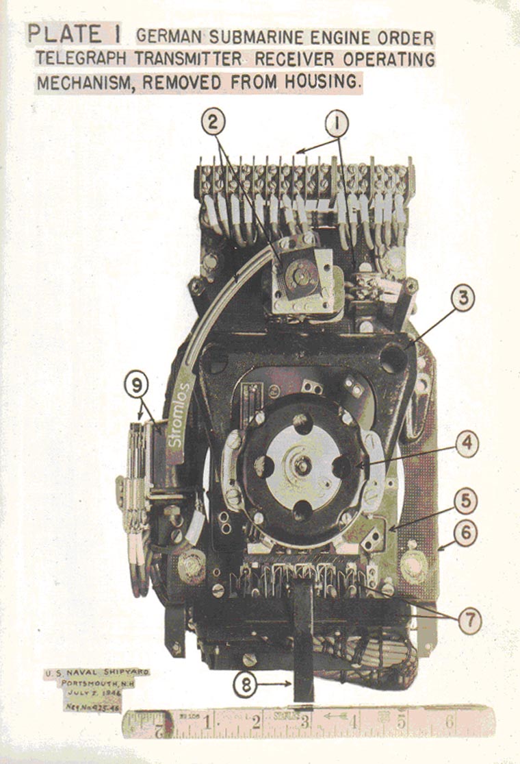
9C-S65 |
||
| PLATE #2 GERMAN SUBMARINE ENGINE ORDER TELEGRAPH TRANSMITTER-RECEIVER OPERATING MECHANISM COMPONENTS REMOVED. ALL COMPONENTS FRONT VIEW | ||
| FOR IDENTIFICATION OF COMPONENTS SEE PLATE #1 | ||
- 39 - |
||
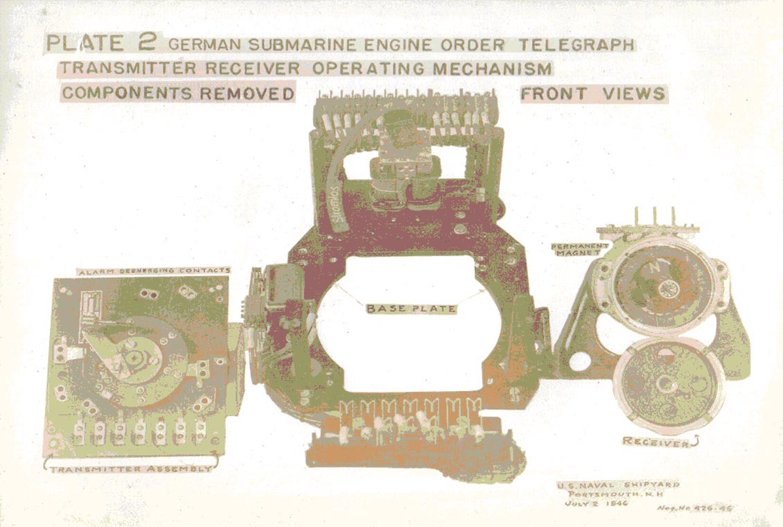
9C-S65 |
||
| PLATE #3 GERMAN SUBMARINE ENGINE ORDER TELEGRAPH TRANSMITTER-RECEIVER OPERATING MECHANISM. ALL COMPONENTS REAR VIEW. | ||
| FOR IDENTIFICATION OF COMPONENTS, SEE PLATE #1 | ||
- 40 - |
||
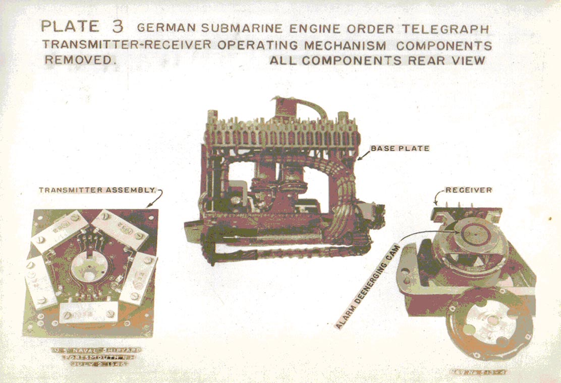
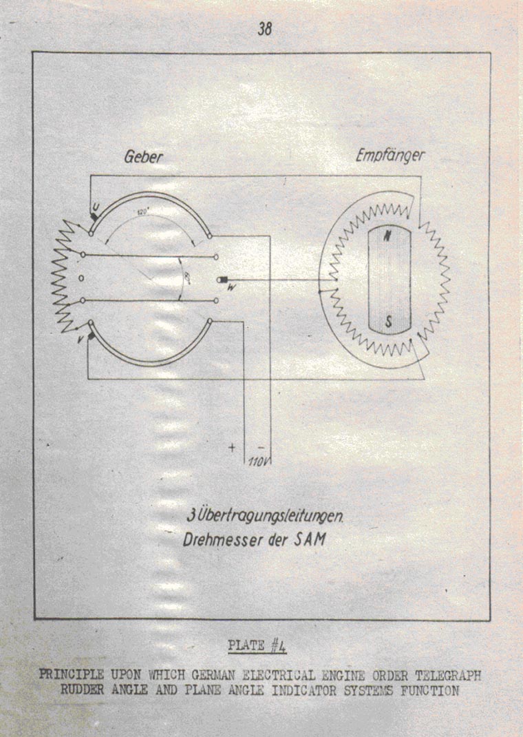
|
|||||
FORMER GERMAN SUBMARINE TYPE IX-C |
|||||
SEARCHLIGHTS |
|||||
SUMMARY |
|||||
| The German vessels had no permanently installed searchlights, nor were pressure-proof outlets provided on the bridge structure. | |||||
| Provision for use of portable 20 centimeter (7.9 inches) and 35 cm (14.2 inches) searchlights was made as follows. From outlets provided in the Conning Tower, the cable attached to the light and the light were led through the bridge hatch, being long enough to allow the operator to take any desired position on the bridge. | |||||
| The 20 cm signal unit was designed to suspend from the operator's neck by means of a canvas strap. The weight of this units was 9.5 pounds as compared to 23 pounds weight of the USN 8" portable unit. | |||||
| Contributing to the difference in weight in favor of the German unit are the following factors: | |||||
| (a) The housing is made of aluminum (or other light weight metal). | |||||
| (b) The simplicity of the shutter mechanism which consisted of a piece of 3/32 inch wall thickness phenolic tubing 2-1/2" in diameter and 4" long actuated by a simple lever mechanism. | |||||
| The power supply for the 20 cm unit was 24 volts 50 cycle A.C. or 24 volts D.C. being obtained either through the use of a step-down transformer or a dropping resistor. | |||||
| A switch was provided as an integral part of the unit to energize or deenergize the circuit as required. The bulb used was a 100-watt incandescent type, silvered on the end to insure that all light emitted was reflected light as an essential requirement of | |||||
- 1 - |
|||||
9C-S66 |
||
| type shutter mechanism used. | ||
| The shutter mechanism was operated with the right hand, while the switch was energized with the left. In addition, a focusing device was provided for use of the right eye. No left hand units were observed. | ||
| Plans available indicate that some type IX-C vessels were provided with the 20 cm and 35 cm light, while others were provided only with the 20 cm light. There were no 35 cm searchlights available on vessels at Portsmouth. The trend of the German on later type vessels was to provide an outlet for only the 20 cm signaling searchlight. | ||
| Tests of visibility and maneuverability were made on U-873 while on trials which place the unit in a very favorable position with regard to the 8" USN signal searchlight. A paragraph of this report is reproduced here for record purposes. | ||
| "On a bright day with the sun not behind the sending searchlight, the German light may be used at a range of approximately 4500 yards without the aid of binoculars. Under similar conditions the USN 8" searchlight can be read at a distance of about 2500 yards. With a bright sun behind the sending light, the German searchlight can be read at about 1700 yards. The USN 8" searchlight can be read at about 1300 yards under the same conditions." | ||
| For additional information regarding the operating characteristics of the German 20 cm unit as compared with the USN 8" and 12" signal searchlights, reference should be made to Enclosure (a) of Officer-in-Charge U-873 letter U873/866 Serial (44) of 8 April 1946. | ||
| Two 20 cm lights have been forwarded to the Bureau of Ships Code 660 for detailed study. Reference should be made to the report to be written by that activity when it has been completed. | ||
May, 1946 |
||
PORTSMOUTH NAVAL SHIPYARD, PORTSMOUTH, N. H. |
||
- 2 - |
||
|
|||||
FORMER GERMAN SUBMARINE TYPE IXC |
|||||
RADIO AND RADAR |
|||||
SUMMARY |
|||||
| The German radio and radar electronic components reflect the considerable engineering thought given to mechanical design for the purpose of saving space and providing installation and maintenance accessibility. | |||||
| The only means provided for communication between the radar and the Conning Tower in which the TDC is installed consists of a voice tube. It is assumed that the German did not seriously associate radar with fire control equipments. | |||||
| Installation practices are considered inferior to USN practices. | |||||
July, 1946 |
|||||
PORTSMOUTH NAVAL SHIPYARD, PORTSMOUTH, N. H. |
|||||
- 1 - |
|||||
9C-S67 |
||
| A. Introduction | ||
| The purpose of this report is to present the number, type function and methods of installation of German radio and radar equipment installed in this type vessel. | ||
| German equipments have been made available to the Naval Research Laboratory for detailed exploitation either from the Shipyard or directly from Germany. In addition, N.R.L. personnel have made field tests of installed equipments on German vessels operated by USN personnel. At present only preliminary reports from the Laboratory are available to the Shipyard, these are presented on Encl. (A) to N.R.L., Conf. ltr. C-EF30 (R130A) to CNO of 29 May 1946. | ||
| In addition, separate reports have been prepared by the Shipyard and have already been distributed. These reports are written on the following equipments | ||
| 1. Receiver Type ELA 1012 (Broadcast Res.) Report 2G-GEN-S67A of January 1946 | ||
| 2. Receiver Type E52b-1 Ln 21000-6 (Short Wave Recr.) Report 2G-GEN-S67B of January 1946 | ||
| 3. Transmitter Type T-200-FK39c (200 Watt - 3 to 23 megacycles) Report 2G-GEN-S67C of February 1946. | ||
| B. Descriptive | ||
| The Germans provided two separate rooms for installation of electronic equipment, namely, a Sound Room and a Radio Room. The only means provided for communication between these rooms and the C.T. and C.R. is a voice tube. | ||
| All components of radio and radar systems are located in one or the other of these rooms. In nearly all vessels of this type the following equipments are located in the Radio Room. | ||
| 1. Radio Transmitter - 200 Watt; 3-24 Megacycles Type - T-200-FK39c Manufactured by Telefunken. | ||
| 2. Radio Transmitter - 150 Watt; 300-600 Kilocycles Type 21131S Manufactured by Telefunken. | ||
| 3. Short Wave Receiver 1.5 - 25 Megacycles Type E52b - Ln 21000-6 Manufactured by Cologne. | ||
- 2 - |
||
9C-S67 |
||||||||||||||
| 4. Broadcast Radio Receiver Type ELA1012 Manufactured by Telefunken. Used mainly as entertainment broadcast receiver. Frequency bands as follows: | ||||||||||||||
|
||||||||||||||
| 5. Short Wave Radio Receiver, 20-1000 Meters Type E 437 S4/41 | ||||||||||||||
| 6. Radar Surface Search Type SG200. Consists of the following separate units: | ||||||||||||||
| a) Transmitter - Type S-200 O.P. Freq. 68cm Repetition Rate 450 C.P.S. | ||||||||||||||
| b) Receiver Type S-6-200 | ||||||||||||||
| c) Indicator ("A" Type Presentation) Provision made for lobe switching, but device not present in antenna system. | ||||||||||||||
| d) Voltage Regulator Panel Type SGLE053/1 | ||||||||||||||
| e) Control Unit - F200 | ||||||||||||||
| f) Antenna Switch and Duplexer | ||||||||||||||
| g) Antenna - Similar to old S.C. Antenna. Houses in Bridge Fairwater and is hoisted by compressed air. Entrance thru pressure hull in Control Room. Hand training only from Radio Room | ||||||||||||||
| 7. Radio Direction Finder Type T3P11a3B consists of the following units: | ||||||||||||||
| a) Regenerative Receiver | ||||||||||||||
| Bands I-IV 70-1200 Kilocycles | ||||||||||||||
| Band V 15-33 Kilocycles (used under water) | ||||||||||||||
| b) Power Supply Unit Type EN410S | ||||||||||||||
| c) Antenna - Direction Finder Loop. Hand training from Radio Room. 360° Train - Then reverse Slip Rings not used. Gyro input provides means for obtaining true and relative bearing. Loop is housed in Bridge Fairwater and is hoisted by compressed air. Entrance thru pressure hull in Control Room. | ||||||||||||||
| 8. 220 V 50 Cycle and 110 V D.C. Distribution Panel. | ||||||||||||||
- 3 - |
||||||||||||||
9C-S67 |
||
| 9. Antenna Connection Boxes and Patch Cords. | ||
| 10. Portable Typewriter | ||
| 11. Control Loudspeaker for combination 1MC and Entertainment Broadcast. | ||
| The following radio and radar system components are located in the Sound Room. | ||
| 1. All Wave Radio Receiver 20-20,000 Kilocycles. Manufactured by Telefunken. Estimated to be at least a 12 year old model. | ||
| 2. Emergency Radio Transmitter, 40 Watt 20-80 Meter. Control Panel type EBG LO 39a | ||
| 3. VHT Trans-Recr. Freq. Range unknown, Type 10UK39. Crystal controlled. Consists of Transmitter Receiver and Power Supply. | ||
| 4. Radar Detector Equipment. Consists of the following units: | ||
| A. (a) 2 Tunis Antenna (one spare) These units are portable and consist of a back to back 9CM Dipole and Reflector and a 3 CM Horn. Detector units for each system are mounted on the back of each of the two antennae. These antennae are mounted on a wooden stick on the bridge and are rotated by hand. Both sections of the antenna feed thru their respective crystal detectors into portable cables which are led down thru the Bridge Hatch to jacks in the C.T. and hence to the Amplifiers in the Sound Room listed as (b) and (c) below. | ||
| (b) 3 CM Amplifier and Power Supply | ||
| (c) 9 CM Amplifier and Power Supply | ||
| B. 165 - 175 CM Detector and amplifier antenna mounted on Schnorchel. Name Plate Data or Instruction Books not available on above equipments. | ||
| 5. Life Boat Portable Transmitter "Mae West" type Freq 600 Meter. Has automatic "SOS" button. Antenna supported by inflated balloons. | ||
| Inspection of German circuit design indicates that progress has not been as rapid nor as advanced as that of USN. However, the attention to mechanical design is particularly noteworthy. These features are | ||
- 4 - |
||
9C-S67 |
||
| discussed in detail in the individual reports prepared by the Shipyard and it is presumed will be discussed in reports to be prepared by the Naval Research Laboratory. | ||
| Installation practices observed are as follows: | ||
| 1. Adequate apace is provided for operation and maintenance of equipments. | ||
| 2. All components are mounted on bonded rubber mounts in compression, tension or shear for shock protection. | ||
| 3. The majority of the above mounts are secured to the wood compartmentation, on the heavier units they are secures to the steel deck as well. | ||
| 4. Rubber covered shielded cables, single and multi conductor, not heat and flame retardant, are employed in electronic circuits. | ||
| 5. The shields of the above cables are thoroughly grounded at each point of entrance to components. | ||
| 6. Power Training is not provided in any system. | ||
| 7. Lead and cable identification is consistent with German practices as discussed in Report 2G-9C-S28. | ||
| 8. Terminal blocks as described in Report 2G-9C-S65 are used extensively. | ||
| 9. Connections are generally made by tinning the end of the lead, rather than employing terminals. | ||
| 10. Except for antenna leads all cables are run in community cable banks. | ||
| 11. Cable supports in way of the radio and sound rooms are secured to the wooden compartmentation by means of wood screws. | ||
| 12. The only radio and radar leads run external to the two rooms are the power supplies and the antenna leads. | ||
| The antennae listed below are installed: | ||
| 1. Surface search radar bedspring type. Similar to old SC type. Hoisted by air from Control Room. Trained by hand from Radio Room. | ||
| 2. Radio Direction Finder Loop Antenna. Hoisted by air from Control Room. Trained by hand from Radio Room. On some vessels a stub antenna for VHF equipment is mounted on the loop. | ||
- 5 - |
||
9C-S67 |
||
| 3. Dipole Antenna for radar intercept equipment is mounted on the Schnorchel. | ||
| 4. Wire rope antenna for radio transmission and receiving as follows: | ||
| a) Transmitting antenna - Runs from forward bridge structure to within a few feet of the bow on centerline. | ||
| b) Receiving Antennae - Two installed, one port and one starboard, run from after bridge structure to within a few feet of the stern on each side. They are relatively low and it is believed their usefulness would be diminished in a heavy sea. | ||
| The three wire rope antennae are not brought thru the pressure hull in a common trunk. Each antenna is brought thru the pressure hull individually. For detailed information with regard to the German antennae layout and method of bringing the wire rope antennae thru the pressure hull reference should be made to the: "Beschreibung und Betriebvorschrift der Bu M Anlage U Boote Typ IXC und IXD2" (Description and Operating Instructions for Interior Communication Systems Submarines Type IXC and IXD2), and to: "Beschreibung und Betriebvorschrift Antennenanlagen auf U1228 (Description and Operating Instructions for Antennae Systems on U1228). | ||
| Antennae leadings, transmitter antennae connections and receiver antennae connections are brought together in suitably designed jack boxes. Patch cords are used to make the desired connections. | ||
| German practices, materials used as well as insulator design in the antennae systems inspected offer nothing unique or new to USN techniques. | ||
| Power supplies are obtained from the sources indicated below. A motor generator of the type used for the power supply of the 200 Watt transmitter type T200 FK39C has been shipped to the Bureau of Ships Code 660 for detailed exploitation and reference should be made its report when it becomes available. | ||
- 6 - |
||
9C-S67 |
||
| Conclusions | ||
| The merit of the different installed systems must necessarily await the completion of the bench and field tests by U.S.L. personnel. | ||
| Early indications are that the equipments are electrically at least equal to comparable USN equipments and mechanically, the designs with regard to space, access and control are definitely superior to USN equipments. | ||
| The German practice of providing a separate Sound Room is noteworthy particularly when considered in light of relatively elaborate installations in USN submarines. | ||
| The individual detail installation practices rest on their own merit, if any. | ||
- 7 - |
||
|
|||||
FORMER GERMAN SUBMARINE TYPE IXC |
|||||
SONAR EQUIPMENT |
|||||
SUMMARY |
|||||
| The German Sonar installations in this type vessel consist only of the bare essentials necessary to operate a submarine. -- namely -- a listening equipment, an underwater telegraphy system and a fathometer. | |||||
| The components of the installed equipments are mechanically and electrically well designed with the emphasis being on the mechanical design. | |||||
| Echo ranging equipment was not installed nor are any of the equipments electrically connected with fire control circuits. Bearing repeaters are not installed. | |||||
| A voice tube provide the only means of communication between the Sound Room and the Conning Tower. | |||||
| External shock mounting in form of bonded rubber mounts in compression, shear and tension are used thruout on inboard components. | |||||
| The effectiveness with which the German submarine operated thruout the war is an indication that considerable ability was manifested by the German operating personnel. | |||||
July, 1946 |
|||||
PORTSMOUTH NAVAL SHIPYARD, PORTSMOUTH, N. H. |
|||||
- 1 - |
|||||
9C-S68 |
||||||||||||||
TABLE OF CONTENTS |
||||||||||||||
|
||||||||||||||
- 2 - |
||||||||||||||
9C-S68 |
||
| A. Introduction | ||
| The scope of this report is to present in a general manner the systems installed and practices of installation. | ||
| Components of complete systems have been made available to Underwater Sound Laboratory, Fort Trumbull, New London, Conn., for bench testing and detailed exploitation. In addition Underwater Sound Laboratory personnel have been operating with the German vessels, making field tests and comparisons with USN equipment installed in the German vessels for that purpose. Two of these reports are available at present, others may be added to the list when they become available. | ||
| Those available are: | ||
| (a) NRL Memo C-471-657/45 dated 10 July 1945 | ||
| (b) USL (interim) Report No. 47 dated 17 April 1946 by D.M. Sherwood. | ||
| In addition all late type sonar equipment used in the German Navy, surface and submarine, as well as a history of sonar in the German Navy is contained in detail in Nav Tech Report No. 530-45 dated 31 October 1945. | ||
| The following instruction books contain pictorial drawings, diagrams, and schematic diagrams of installed systems. | ||
| 1. Sonore UT-Anlage fur U-Boote (Sonar - Under-water Telegraphy System for submarines) The above equipments manufactured by Atlas-Werke, Aktiengesellschaft. | ||
| 2. Beschreibung und Bedienungs - vorschrift einer Wasserschallsignal - Sende - Emfangsanlage. (Description and Operating Instructions for a Water Wave Signal - Transmitting and receiving Systems) The above is U.T. Sonar manufactured by "Electroacustic Werke. It is essentially the same as that manufactured by "Atlas Werke" | ||
| 3. "Kabelplane" Cable plans for Electronic Installations and location of components. | ||
| 4. "Unterwasserschall - Gruppenhorchanlage" (Under-water signal Group Listening System) The above is manufactured by "Atlas Werke - Aktiengesellschaft" | ||
- 3 - |
||
9C-S68 |
||
| B. Descriptive | ||
| The following systems are installed in this type vessel. | ||
| (a) Group Listening System (GHG) | ||
| (b) Underwater Telegraphy System (U.T.) | ||
| (c) Fathometer (Echolot) | ||
| A separate sound (not sonar) room is provided in which the following equipments were installed common to all vessels. | ||
| (a) G.H.G. Listening Equipment | ||
| (b) Radar Detection Units | ||
| (c) Shaft R.P.M. Indicators | ||
| (d) Gyro Repeater | ||
| (e) Voice tube connection | ||
| (f) Bench space for maintenance and writing. | ||
| (g) Rudder Angle Indicator | ||
| (h) A stool with spare parts stowage below the seat. | ||
| In addition to the above other electronic equipments are installed in the Sound Room presumably in accordance with the Captain's desires in that they vary from vessel to vessel. Among those more commonly found in the Sound Room are the following: | ||
| (a) 40 Watt Emergency Radio Transmitter | ||
| (b) "Mae West" Transmitter | ||
| (c) General Announcing Control and Amplifier Panel. | ||
| The location of the components is covered in detail by reports and instruction books referenced in "Introduction". | ||
| Inspection of installations reveal the following practices which were common to all systems unless otherwise indicated. | ||
| 1. Cables passing thru watertight bulkheads are grouped in the main cable banks and pass thru the community stuffing box. | ||
| 2. Identification of cables and leads is kept to the bare minimum required by German practices. See Report 2G-9C-S28 for detail discussion. | ||
- 4 - |
||
9C-S68 |
||
| 3. A wide use of terminal boards thruout the systems similar to those described in report 2G-9C-S65. | ||
| 4. All armor and shielding is thoroughly grounded at entrance points to components at the gland nuts of the tube terminals. | ||
| 5. Strict attention to small design details which make for easy access, removal, and maintenance. | ||
| 6. Physical grouping of related electrical components in common subassemblies which are electrically connected to other portions of the main assembly by means of plugs and jacks. | ||
| 7. Designs which minimize the possibility of incorrect reassembly or replacement. | ||
| 8. Controls and adjustments are kept to a minimum consistent with German practice in other electronic and electrical equipments. | ||
| 9. Cables thru the pressure hull are usually of portable watertight construction. The method of making the stranded individual conductor watertight is as follows. Each conductor is made up of eight strands. The center strand has applied to it a layer of rubber approximately 1/32" thick. The other eight strands are spirally wound around this rubber covered center strand in such manner that they are embedded in the rubber so as to approach a solid cross section. The individual conductor rubber is molded over the above assembly thus tending to fill all interstices with rubber. These cables are usually two conductor. The conductors as assembled above are twisted and a rubber outer sheath molded over them in such manner that a cross section of the cable appears solid. | ||
| 10. Circular rubber packing of rectangular cross section is used in tube terminals and stuffing tubes thruout at cable entrances. | ||
- 5 - |
||
9C-S68 |
||
| 11. Metallic gland nuts are used in all cases except where portable cables enter tube terminals, here phenolic gland nuts are used. | ||
| 12. G.H.G. hydrophone leads are divided into two groups, one port and one starboard. From a connection box in the forward torpedo room, each group of twenty-four portable cables is passed thru the hull. The method for accomplishing this is as follows. A relatively large hole os cut out of the pressure hull over which a suitable plate is welded. This plate has presumably had the necessary stuffing tubes preassembled in the shop. | ||
| 13. In addition to the watertight cable described under 9. The German provides a backup feature as follows. Where the portable cable enters a tube terminal a small 3 jaw steel clutch type clamp is assembled on the outer sheath of the cable, inserted in the tube terminal and then the rubber packing is assembled in the usual manner. | ||
| 14. All inboard components of the systems are mounted on bonded rubber mounts in compression, shear and tension to provide for shock mounting and sound isolation. | ||
| In addition to the installed equipments provision for depth sounding in emergency is provided as follows. In the Conning Tower six boxes of ten "Electroloten" are stowed. This device is a small expendable bomb about six inches long and crudely streamlined with a considerable tail fin structure. It was thrown overboard from the deck and would sink to the bottom at a constant known velocity. It was arranged to explode on contact with the sea bottom. The depth of the water is computed by measuring with a stop watch, the elapsed time from the moment when the bomb struck the water to the moment when the explosion was heard. | ||
- 6 - |
||
9C-S68 |
||||||||||||||||||||||||||||||||||||||||||||||||||||
|
||||||||||||||||||||||||||||||||||||||||||||||||||||
| The above motor generator sets and their associated controls are located in the Maneuvering Room. Power for the motors is obtained in such manner that by making the proper external connections the sets will operate satisfactorily from voltages of 110-170 DC or from 220-340 D.C. Dropping resistors are incorporated to make this possible. | ||||||||||||||||||||||||||||||||||||||||||||||||||||
| The 220 V 50 Cycle and the regulated 110 V D.C. power supplies required for energizing the electronic equipment are fed into a common distribution panel. From the above buses in the panel the individual circuits are run. These circuits are fused only and are not provided with disconnect switches. Fuses are accessible thru the front of the panel and are of the type described in Report 2G-9C-S62-2. A nameplate is mounted to identify each set of fuses with the circuit energized. | ||||||||||||||||||||||||||||||||||||||||||||||||||||
- 7 - |
||||||||||||||||||||||||||||||||||||||||||||||||||||
9C-S68 |
||
| C. Conclusions | ||
| It is not believed the German practices with regard to installation are superior to USN practices. From inspection of circuit designs at the Shipyard, it would appear that USN designs are well in advance of German designs. Final conclusions however, may be drawn when the reports of detailed exploitation by the Naval Research Laboratory become available. The considerable thought given to space, ease of accessibility for replacement of parts for repair or maintenance, and, in certain equipments, the use of multipurpose tubes is noteworthy. | ||
- 8 - |
||
|
|||||
FORMER GERMAN SUBMARINE TYPE IXC |
|||||
ELECTRICAL INSTRUMENTS |
|||||
PORTABLE AND INSTALLED |
|||||
SUMMARY |
|||||
| German installed meters are of no better design than late type hi-shock USN meters of comparable size and scale face. For the most part they exist in the same varieties and types found in USN submarines. The majority, being ammeters & voltmeters, operate on the D'arsonval principle. | |||||
| As nearly as can be determined portable meters for various purposes are not supplied in the types and quantities found aboard USN submarines. | |||||
| Certain meters and instruments have been made available to BuShips Code 660 for detailed exploitation. | |||||
| All German submarines are provided with electronic ampere hour meters by means of which the condition of the main battery is determined. | |||||
| External shock mounting in form of bonded rubber mounts in compression, tension, and shear are used extensively on components which have meters and instruments installed in then and on the meter or instrument housings where mounted separately. | |||||
July, 1946 |
|||||
PORTSMOUTH NAVAL SHIPYARD, PORTSMOUTH, N. H. |
|||||
- 1 - |
|||||
9C-S69 |
||
| 1. Introduction | ||
| The scope of this report is to present in a general manner the observations obtained in calibrating and repairing German meters at the shipyard. | ||
| In addition the German application of meters and instruments may be obtained from the various German instruction books referenced thruout the other reports on type 9C vessels. | ||
| The following listed meters and instruments have been forwarded to BuShips Code 660 for detailed exploitation and reference should be made to their reports when they become available. | ||
| (a) Electrolytic Ampere Hour Meter | ||
| (b) Voltmeter | ||
| (c) Combination Ammeter and Voltmeter | ||
| (d) Megger (0-12 Megohms) | ||
| (e) Megger (0-20 Megohms) | ||
| 2. Descriptive | ||
| German meter elements vary in size dependent upon use. They are found in housings designed for surface, semiflush, or flush mounting as required by the given installation. These housings are from 1-1/2" to 3" in diameter and except for the smaller ones up to about 3" in diameter are made from pressed steel stampings. A removable front cover is provided for protecting the meter elements from foreign matter. Suitable shatterproof glass is assembled in the cover to protect the meter element from foreign matter and provide a means of viewing the scale face. "Antiglare" feature normally found in USN installed shipboard meters was not observed. Meters installed as part of a switchboard or distribution board have studs protruding from the rear of the housing. Meters which are mounted directly to the hull and not assembled with other equipments have their studs brought out at the bottom into a connection box which is an integral part of the meter housing. A watertight seal for the connection box is obtained by means of socket type rubber gaskets. Ammeter shunts are mounted in this box. Terminal boards of this type described under General in Report 2G-9C-s65 are used in these applications. | ||
- 2 - |
||
9C-S69 |
||
| Most meter housings of the smaller size are molded phenolic for surface or flush mounting with provisions for making connections at the rear. Tapped metal inserts are provided for the external and internal connections. | ||
| Dial faces are graduated in an arc of 90° in most cases and never more than 270°. Provision is made for zero centering without removal of the front cover. | ||
| Since the large majority of installed meters are D.C. type it is presumed that the maximum design effort was spent on these. While the results of details exploitation and any laboratory tests as may be made on meters sent to BuShips Code 660 are not available as yet, the following observations are set forth: | ||
| a) Meter elements are not designed nor manufactured to approach laboratory instrument requirements to the degree that USN meters do. It is believed German meter elements are adequate for the purpose intended. | ||
| b) All operate on the D'Arsonval principle. | ||
| c) Permanent magnets of "Alnico" characteristics are used. However, in the larger elements, the Germans did not use this feature to advantage in space saving. | ||
| d) Workmanship and manufacturing methods are equal to but not better than USN meters. | ||
| e) Accessibility for maintenance and calibration is not as good as normally found in USN meters. | ||
| f) Ammeters are designed to be used with either a 60, 75, 200, or a 300 M.V. drop shunt. Calibrated leads are not provided by the manufacturer. This required lead size is found on the scale plate directly under M.V. drop marking. Calibration is accomplished at the installation. | ||
| g) Two position adjustments are available for balancing rather than the three normally found in USN meters of this type. | ||
| h) Base plates are in general considerably larger than those in USN meters. | ||
| i) It is not believed that German meters would meet USN meter high shock requirements. | ||
| j) Voltmeters D.C. ohms per volt vary from 100 to 200 ohms. | ||
- 3 - |
||
9C-S69 |
||||||||||||||||||||||||||||||||||||||||||||
| The German favored tubular shunt which consisted of a suitable number of approximately 1/4" O.D. tubes assembled between the end blocks. An advantage of this type of shunt is that it minimizes the need for additional support when mounted in other than the vertical position. Cooling fins are not provided nor are they as necessary with this type shunt. | ||||||||||||||||||||||||||||||||||||||||||||
| In the smaller sizes where only one bar is required the German resorted to the flat bar shunt similar to those normally found in USN installations with the exception that the flat bar usually had several deep waves incorporated in it to improve ventilation and decrease space required. | ||||||||||||||||||||||||||||||||||||||||||||
| The following types of meters are found installed in German circuits, electrical and electronic: | ||||||||||||||||||||||||||||||||||||||||||||
|
||||||||||||||||||||||||||||||||||||||||||||
- 4 - |
||||||||||||||||||||||||||||||||||||||||||||
9C-S69 |
||||||||
| While no standard allowance list appears to be available it is believed the following list of portable meters enumerates the majority of those placed aboard. No separate meter room or locker is provided, the instruments being placed in care of the interested department for care and stowage, much the same as in USN practice. | ||||||||
|
||||||||
| 3. Conclusions | ||||||||
| German design and application of meters and instruments are satisfactory for purposes intended. There is nothing unique in design or manufacturing methods as nearly as can be determined from observations made of the installations on board or in the instrument room. Reference should be made to BuShips Code 660 reports on meters shipped there for study. | ||||||||
- 5 - |
||||||||
|
|||||
FORMER GERMAN SUBMARINE TYPE IX-C |
|||||
SIGHT SIGNALLING APPARATUS |
|||||
SUMMARY |
|||||
| The vessel was provided with searchlights, a limited number of signal flags, semaphore flags, star signal pistols and pyrotechnics. Local information does not provide any detail with respect to units other than the signal searchlights. | |||||
July, 1946 |
|||||
PORTSMOUTH NAVAL SHIPYARD, PORTSMOUTH, N. H. |
|||||
- 1 - |
|||||
9C-S70 |
||||||||||
C O N F I D E N T I A L |
||||||||||
SIGHT SIGNALLING APPARATUS |
||||||||||
| Equipment listed is as follows: | ||||||||||
|
||||||||||
| The signal searchlights are discussed in detail in the S66 section of the report. Both operate on 24 volts. | ||||||||||
| The signal flags do not comprise an entire set, but are limited to a few special flags. Those found consist of: | ||||||||||
|
||||||||||
| One single barreled and one double barreled signal pistol is located in the conning tower. Ammunition listed in the general information book consists of: | ||||||||||
|
||||||||||
| The character of the pyrotechnics is unknown. Eight pieces are listed, with their firing units. | ||||||||||
| Ten ESN cartridges (character unknown) are also listed. | ||||||||||
July, 1946 |
||||||||||
PORTSMOUTH NAVAL SHIPYARD, PORTSMOUTH, N. H. |
||||||||||
- 2 - |
||||||||||
|
|||||
FORMER GERMAN SUBMARINE TYPE IXC |
|||||
FIRE CONTROL EQUIPMENT |
|||||
SUMMARY |
|||||
| German installation of fire control equipment with provision for electrical connection with radar, sonar and optical systems is of an elementary nature. Present design USN submarine fire control installations are far in advance of German installations observed here. | |||||
July, 1946 |
|||||
PORTSMOUTH NAVAL SHIPYARD, PORTSMOUTH, N. H. |
|||||
- 1 - |
|||||
9C-S71 |
||||||||
TABLE OF CONTENTS |
||||||||
|
||||||||
- 2 - |
||||||||
9C-S71 |
|||||||||||||||||||||||||||||||||||
| A. Introduction | |||||||||||||||||||||||||||||||||||
| The scope of this report is to enumerate the equipment installed, their location and interrelation as well as the method employed in installation. | |||||||||||||||||||||||||||||||||||
| In view of the fact, that equipments of interest to the Bureau of Ordnance, have been shipped as directed for detail study and observation, no attempt will be made to delineate the various components. As yet no reports on these equipments have been made available for incorporation or reference in this report. | |||||||||||||||||||||||||||||||||||
| The Shipyard library does not contain any German instruction books on the individual components. | |||||||||||||||||||||||||||||||||||
| For detail information with regard to torpedo tubes and periscopes reference should be made to the applicable reports in this book. | |||||||||||||||||||||||||||||||||||
| B. Descriptive | |||||||||||||||||||||||||||||||||||
| The components installed in this system are enumerated below with their locations. | |||||||||||||||||||||||||||||||||||
|
|||||||||||||||||||||||||||||||||||
- 3 - |
|||||||||||||||||||||||||||||||||||
9C-S71 |
||||||||||||||||||||
|
||||||||||||||||||||
| German fire control equipment installation practices follow closely practices employed in I.C. installations. The following observations are set forth: | ||||||||||||||||||||
| (a) Servo motors used are conventional series type energized from the regulated 110 V. D.C. supply. | ||||||||||||||||||||
| (b) Synchro systems are energized from 55 volt, 50 cycle power supply which is obtained from the 220 V. 50 cycle A.C. supply by means of transformers. | ||||||||||||||||||||
| (c) Synchro generators, one and thirty-six speed are provided with a positive spring loaded jaw clutch to engage the gear train and an azimuth and pointer on the other which considerably facilitate alignment of a synchro system and is worthy of consideration fir use in fire control circuits as elaborate as those installed in U.S.N. vessels. The periscope bearing transmitter furnishes one example of this feature. | ||||||||||||||||||||
| (d) Cable and lead designations, marking, are consistent with German practices delineated in Report 2G-9C-S28. | ||||||||||||||||||||
| (e) Terminal boards used throughout the system are of the same type as described in Report 2G-9C-S65. | ||||||||||||||||||||
| (f) Cables are led from compartment to compartment as required in the closest cable bank and through the community stuffing box provided in the watertight bulkhead. | ||||||||||||||||||||
| (g) The circuits are not grouped to be controlled from a common switchboard as is the usual practice in U.S.N. submarines. | ||||||||||||||||||||
| (h) Rubber mounts in compression tension, and shear provide the necessary shock and sound isolation protection. | ||||||||||||||||||||
- 4 - |
||||||||||||||||||||
9C-S71 |
||
| (i) Fuses and relays associated with the TDC and Gyro angle setters are mounted in a separate, relatively large, quick opening connection box to minimize the need for getting into these equipments and thus contributing to their appearing relatively small as compared to U.S.N. units. | ||
| (j) Captive screw, plug and jack type connections, designs to minimize incorrect assembly are used profusely. | ||
| (k) Components are readily accessible for maintenance and repair. | ||
| Conclusions | ||
| In general, German practices are below the standards required for comparable U.S.N. installations. | ||
- 5 - |
||
|
|||||
FORMER GERMAN SUBMARINE TYPE IX-C |
|||||
TURRETS |
|||||
SUMMARY |
|||||
| As there are no turrets except on the type 21 vessels, this section is inserted merely for reference. | |||||
July, 1946 |
|||||
PORTSMOUTH NAVAL SHIPYARD, PORTSMOUTH, N. H. |
|||||
|
|||||
FORMER GERMAN SUBMARINE TYPE IX-C |
|||||
BROADSIDE GUNS |
|||||
SUMMARY |
|||||
| As originally armed, the vessels had: | |||||
| one 105 mm gun on the main deck forward of the conning tower with a spray shield. | |||||
| Ready service ammunition, stowed in pressure proof tanks, consisted of 32 rounds. | |||||
| 218 additional rounds were stowed in the two magazine spaces below decks. | |||||
| This gun was removed when the anti-aircraft armament was increased. See the S74 report section. | |||||
July, 1946 |
|||||
PORTSMOUTH NAVAL SHIPYARD, PORTSMOUTH, N. H. |
|||||
|
|||||
FORMER GERMAN SUBMARINE TYPE IX-C |
|||||
ANTI-AIRCRAFT GUNS |
|||||
SUMMARY |
|||||
| Original anti-aircraft armament consisted of one 37 mm gun on the main deck aft, and one 20 mm gun at the after end of the cigarette deck. In addition, one 8 mm type C/34 machine gun was provided. Ready service tanks were provided topside only for the 37 mm gun. | |||||
| As changed at the time of the general re-armament of the submarines, the vessels were provided with several different combinations of 20 mm and 37 mm guns, usually consisting of two twin 20s on the cigarette deck wings and a single 37 on the after extension of the cigarette deck. This was not uniform, however, for twin 37 mm gun mounts have been observed on some vessels at Portsmouth. With the guns were provided the usual pressure proof stowage for spare barrels, ready service lockers and dip pots. | |||||
| Pipe guards limit the depression angle at which the guns can be fired. | |||||
July, 1946 |
|||||
PORTSMOUTH NAVAL SHIPYARD, PORTSMOUTH, N. H. |
|||||
|
|||||
FORMER GERMAN SUBMARINE TYPE IXC |
|||||
TORPEDO HANDLING, LOADING AND STOWAGE |
|||||
SUMMARY |
|||||
| The handling, loading and stowage of torpedoes on the type IXC submarines is different in many respects from American practice. The German used lighter handling and stowage equipment in the forward and after rooms, but on the contrary, used a large number of topside stowage tubes to carry sufficient spare torpedoes. No particular effort was made to provide handling and stowage gear for rapid reload. | |||||
February, 1946 |
|||||
PORTSMOUTH NAVAL SHIPYARD, PORTSMOUTH, N. H. |
|||||
- 1 - |
|||||
9C-S75-3 |
||
| 1. INTRODUCTION | ||
| The Type IX C German submarine retains the same basic below deck handling and stowage arrangements as its predecessors, the Type VII submarines. However, more reserve torpedoes can be handled on this later type mainly because of the additional topside stowage tubes provided. | ||
| 2. GENERAL DESCRIPTION | ||
| The principles of the stowage and handling of torpedoes in the torpedo rooms on the IX C are shown on Plates I and II. | ||
| The topside torpedo handling gear varies from U.S. practice in several features. Additional deck arrangements, such as tracks and a dolly, are made necessary by the Germans' extensive use of topside stowage to supplement limited below-decks stowage. The main difference, however, arises from the German practice of lowering the torpedo into the vessel by means of a fitting attached to the after body of the torpedo. The use of this fitting requires an additional high stanchion with its guide wires and fittings clear of the loading hatch. On the IX C a cable arrangement to the deck winch is used for lowering the torpedo into the vessel in lieu of the pulley and crank arrangement shown on plate I. The upper loading cradle is large and presents a stowage problem. U.S. designs utilize the cradle as part of the deck planking. | ||
| Within the vessel no heavy loading cradles are used either for supporting the torpedoes in their stowage or for loading into the vessel. Instead, for stowage, light supporting chocks are used and, for all transport and loading operations, a portable I-beam with its associated rollers and torpedo supporting gear is used (see plate II). | ||
| When lowering the torpedo into the vessel, using the I-beam, an additional short supporting cradle is needed just inside the loading hatch. As the torpedo enters the room, supporting straps from rollers on the I-beam, which has been previously secured in position, are placed around the torpedo. This is am awkward process and adds to the loading time. After the torpedo is lowered against a lower stop, the upper supporting cradle is removed, the I-beam and torpedo are placed in a horizontal position, are moved athwartships by means of two interconnected differential chain hoists and a trolley, and the torpedo is lowered into the chocks. | ||
- 2 - |
||
9C-S75-3 |
||
| The torpedo is then removed from the I-beam and secured in the chocks. This latter process is also time consuming. On U.S. designs the torpedo is already in its stowage cradle and needs but to be rolled athwartships once the cradle is lowered to the horizontal position. | ||
| The utilization of the forward and after torpedo room spaces for combined berthing and stowage facilities seems to favor American designs. The IX C has the trim and WRT tanks within the pressure hull in both the forward and after torpedo rooms. Four reserve torpedoes forward and two aft are stowed over these tanks and below the compartment floor plates. In the forward torpedo room above the floor plates and in an average cross sectional area of approximately 75 sq.ft., ten berths are fitted. In the after torpedo room in an area of approximately 55 sq.ft., 8 berths are fitted. None of this upper space is utilized for carrying reserve torpedoes. On latest U.S. designs, in the forward room above the deck plates in an average sectional area of approximately 125 sq.ft., 8 torpedoes and 17 berths are stowed; and in the after room 14 berths are provided. As all tubes, both forward and aft, are above the floor plates, no reserve torpedoes are on the same level as any of the tubes to be serviced. On the latest American submarines the practice has been to supply two reserve torpedoes for all torpedo tubes at the same level as the tubes, with the exception of the upper tubes aft, in which case only one spare for each tube is provided. | ||
| On the IX C the chain hoist arrangement in each torpedo room for handling torpedoes is built into the ship's structure. Each of the two hoists is arranged on an athwartships trolley. A shaft and gearing mechanism between the trolleys permits simultaneous athwartship movement of the hoists. This built-in arrangement is more convenient than the portable one used on U.S. submarines but does occupy space that can be used for berthing. The arrangement provides positive control of the movement of the torpedo but does limit the speed at which it may be moved athwartships. | ||
| The German technique of loading the torpedoes from the spare stowage has been adapted from that used on earlier types and is a slow cumbersome method. Preliminary arrangements for loading the torpedo into the tube are not completed until the torpedo is raised from its stowage under the deck and lined up with the tube to be serviced, and the I-beam is secured into position by the special securing rods provided. This handling and loading gear is light when compared with heavy cradles and supporting cross beams. However, the sacrifice on reloading times is excessive. The arrangement adopted | ||
- 3 - |
||
9C-S75-3 |
||
| on U.S. submarines requires no excessive amount of handling of the torpedoes prior to reloading. Under most normal circumstances when readying for reload, the cradle (and its torpedo), being on the same level as the tube, need only be rolled athwartships and secured in its loading position by a simple built-in locking device. | ||
| An attempt has been made to reduce noise transmission during handling operations by mounting the chain hoisting gear on rubber. The details of these mountings will be covered under the S40 reports on shock and sound isolation. | ||
| The practice of lowering away the torpedo by attaching to a fitting on the after body has been accepted with much favor by American crews operating the German gear. The main advantage of this over the American method lies in the fact that the lines leading to the deck do not have to pass the maximum diameter of the torpedo. There is no resulting chafing and binding of the cable or rope used, and the diameter of the entrance opening for the loading hatch can be kept at a minimum. Also special torpedo nose fitting for the different types of torpedoes are not required; the cable is attached to the torpedo by means of a light hook that fits into a recess built into the torpedo. When lowering away any large number of torpedoes , the added simplicity of this method becomes more apparent; also the labor required to install the high stanchion involved by this technique becomes minor in nature. | ||
| 3. CONCLUSION | ||
| The total number of reserve torpedoes carried on board the type IX C submarine counting both topside and torpedo room stowage is comparable to total reserve carried on U.S. submarines. However, the inaccessible stowage space allotted these reserve torpedoes and the cumbersome gear required for handling then does not permit rapid reloading of the tubes. It is recommended that no further study be made of the setup as installed on this type. | ||
- 4 - |
||
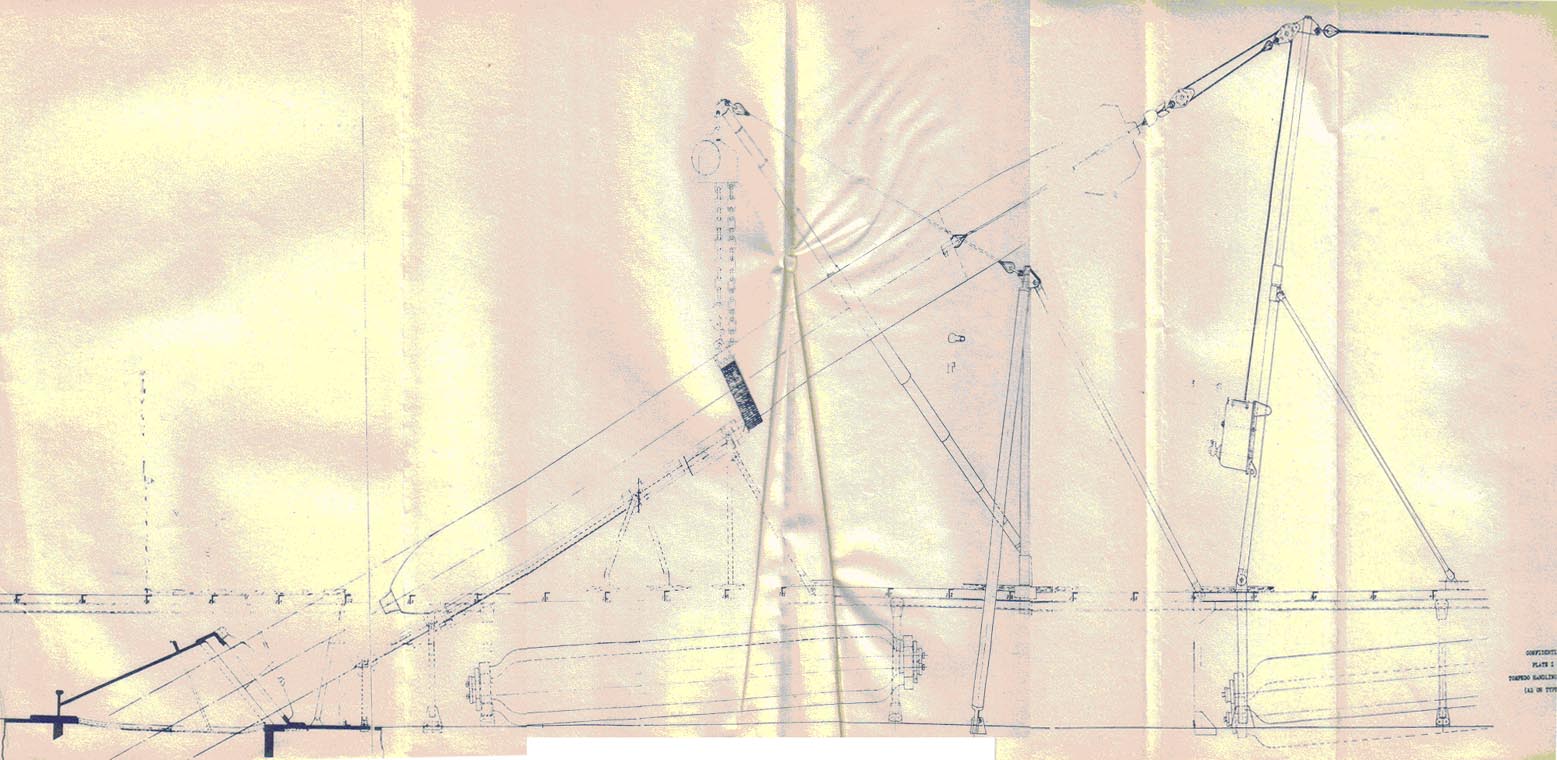
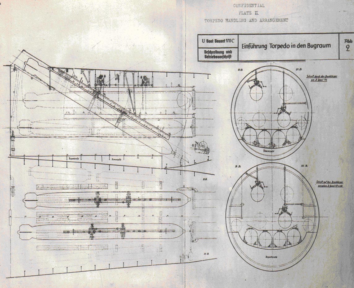
|
|||||
FORMER GERMAN SUBMARINE TYPE IXC |
|||||
MINES AND DEPTH CHARGES |
|||||
SUMMARY |
|||||
| Mine handling has been covered under S75 report. Otherwise this section is inapplicable and the page is inserted only for record purposes. | |||||
July, 1946 |
|||||
PORTSMOUTH NAVAL SHIPYARD, PORTSMOUTH, N. H. |
|||||
- 1 - |
|||||
|
|||||
FORMER GERMAN SUBMARINE TYPE IXC |
|||||
GAS & SMOKE WARFARE APPARATUS |
|||||
SUMMARY |
|||||
| Information is not available with respect to offensive gas and smoke warfare apparatus carried. | |||||
| The only material found locally is one paragraph in the general information book which directs that when gas enters the vessel gas masks are to be put on and the vessel is to be rigged for dive except that the engine air induction is to remain open. Further, after passing through a dangerous zone, the vessel is to be ventilated with the compartment air blowers, and all corners and pockets are to be blown out with compressed air, in order to eliminate any gas. | |||||
| There is also a section devoted to description of the effect of chlorine, nitrogen and oxygen, but as this is concerned solely with abandoning a sunken vessel the section is here mentioned merely for reference. | |||||
July, 1946 |
|||||
PORTSMOUTH NAVAL SHIPYARD, PORTSMOUTH, N. H. |
|||||
- 1 - |
|||||
|
|||||
FORMER GERMAN SUBMARINE TYPE IXC |
|||||
AMMUNITION |
|||||
SUMMARY |
|||||
| A relatively large amount of ammunition was carried. Magazines were installed, provided with appropriate fittings for the material stowed therein and were arranged to permit air circulation and to permit flooding. Air can be drawn from the magazines into the exhaust duct of the compartment ventilating system. | |||||
July, 1946 |
|||||
PORTSMOUTH NAVAL SHIPYARD, PORTSMOUTH, N. H. |
|||||
- 1 - |
|||||
9C-S78 |
||||||||||
| 1. Ammunition | ||||||||||
| Ammunition originally provided was as follows: | ||||||||||
| a) in magazine No. 1 below the control room | ||||||||||
|
||||||||||
| b) in magazine No. 2 below the galley | ||||||||||
|
||||||||||
| c) Conning Tower | ||||||||||
|
||||||||||
| d) Superstructure | ||||||||||
|
||||||||||
| e) within the fairwater | ||||||||||
|
||||||||||
| When the 37 MM gun was placed on board, stowage in both Magazines was altered to provide stowage for 37 MM ammunition boxes. | ||||||||||
| When the arrangement of guns was again altered to one 37 MM and two twin 20 MM guns, and other variations on that arrangement (some vessels had twin 37 or 40 MM guns in lieu of the single 37), the ammunition carried was modified accordingly. According to NAVTECHMISEU report 312-45 the ammunition carried was then 2625 rounds for the single 37 MM gun and 8500 rounds for the two twin 20 MM guns. | ||||||||||
| 2. Ammunition Handling | ||||||||||
| No special ammunition handling devices were provided. All handling was by hand through normal hatches. | ||||||||||
| 3. Magazines | ||||||||||
| Magazines were cork insulated, fitted with wooden lining and dunnage as necessary to insure fitted stowage, and were arranged to permit flooding. | ||||||||||
| The stowage arrangements included simple keeper bars for each layer of boxes, with a socket for one and a pocket for the other end of each bar. | ||||||||||
| In addition stowage for empty machine gun magazines were fitted. The one stowage plan available, Stowage Fittings in Magazine No. 2 (Staugeruste in Munitionskammer 2) Plan No. SII08002, alt. 2 dated 10 August 1943 shows stowage for 11 magazines (20 rounds per magazine), 40 boxes of 20 MM ammunition (11 rounds per box), and three cans of demolition charges (4 charges per can). | ||||||||||
- 2 - |
||||||||||
9C-S78 |
||
| Ventilation consists of a pipe to the compartment air exhaust duct. | ||
- 3 - |
||
|
||||||||
FORMER GERMAN SUBMARINE TYPE IXC |
||||||||
SMALL ARMS |
||||||||
SUMMARY |
||||||||
| Small arms listed in the general information book are: | ||||||||
|
||||||||
| These are all stowed in racks in the Wardroom. | ||||||||
| In addition, there is one 8 MM machine gun. | ||||||||
| Small arms ammunition consists of: | ||||||||
|
||||||||
| No information is locally available which would relate the 98 rifles to the automatic pistol ammunition. There is no reference made to rifle ammunition or to automatic pistols. | ||||||||
July, 1946 |
||||||||
PORTSMOUTH NAVAL SHIPYARD, PORTSMOUTH, N. H. |
||||||||
- 1 - |
||||||||
|
|||||
FORMER GERMAN SUBMARINE TYPE IXC |
|||||
GUN BATTERIES |
|||||
SUMMARY |
|||||
| This section is not believed applicable, and is inserted merely for record. | |||||
July, 1946 |
|||||
PORTSMOUTH NAVAL SHIPYARD, PORTSMOUTH, N. H. |
|||||
- 1 - |
|||||
|
|||||
FORMER GERMAN SUBMARINE TYPE IXC |
|||||
NON-STRUCTURAL SPLINTER PROTECTION |
|||||
SUMMARY |
|||||
| Information is not available as to mine protection, other than that the vessels were originally built with propeller, plane and rudder guards, with cable cutters forward, and with clearing wires. | |||||
| The guards remain, but the cable cutting devices were removed. The clearing wires have been modified by eliminating the saw tooth surface on the extreme forward end of the vessel. | |||||
| Information is not locally available with regard to the type of degaussing employed. | |||||
July, 1946 |
|||||
PORTSMOUTH NAVAL SHIPYARD, PORTSMOUTH, N. H. |
|||||
|
|||||
FORMER GERMAN SUBMARINE TYPE IX-C |
|||||
BOATS |
|||||
SUMMARY |
|||||
| As designed, the vessels of this type carried a dinghy and a collapsible rubber boat. The dinghy was put ashore during war, and nothing is known of its characteristics. | |||||
| The collapsible boat was of the familiar type, inflated by means of compressed air. Several have been forwarded to the Bureau of Ships for exploitation. | |||||
| The dinghy was stowed in the superstructure, and the rubber boat in a pressure-proof tank on deck. | |||||
July, 1946 |
|||||
PORTSMOUTH NAVAL SHIPYARD, PORTSMOUTH, N. H. |
|||||
|
|||||
FORMER GERMAN SUBMARINE TYPE IX-C |
|||||
| These sections do not apply, and are inserted merely for record. | |||||
July, 1946 |
|||||
PORTSMOUTH NAVAL SHIPYARD, PORTSMOUTH, N. H. |
|||||
|
|||||
FORMER GERMAN SUBMARINE TYPE IXC |
|||||
INSTRUMENTS NOT COVERED IN OTHER GROUPS |
|||||
SUMMARY |
|||||
| This section is inapplicable and the page is inserted for record purposes only. | |||||
July, 1946 |
|||||
PORTSMOUTH NAVAL SHIPYARD, PORTSMOUTH, N. H. |
|||||
- 1 - |
|||||
|
|||||
FORMER GERMAN SUBMARINE TYPE IX-C |
|||||
DAMAGE CONTROL |
|||||
SUMMARY |
|||||
| The German arrangements call for the establishment of repair parties, and establish the equipment to be carried on board for repair kits. | |||||
| A number of means exist, of varying the effectiveness for altering trim or correcting a list. The German discussion of damage control for this type of vessel omits, however, any reference to counterflooding. | |||||
July, 1946 |
|||||
PORTSMOUTH NAVAL SHIPYARD, PORTSMOUTH, N. H. |
|||||
- 1 - |
|||||
9C-S88 |
||||||||
C O N F I D E N T I A L |
||||||||
DAMAGE CONTROL |
||||||||
| GENERAL | ||||||||
| Damage control has been in part discussed under the appropriate section of the S29 report. | ||||||||
| No information is locally available with regard to damage control books, or practice instruction. Repair party equipment is discussed in the S29 report. This section will, therefore, be confined to a discussion of compartment check-off lists, repair parties, and of list and trim control. | ||||||||
| CHECK-OFF LIST | ||||||||
| The compartment check-off list was known to the Germans as Tauchtafeln (Diving Tables). It consists of a book which lists, for condition A (fuel ballast tanks as main ballast tanks) and condition B (fuel ballast tanks carrying fuel), and for each compartment, conning tower, bridge and superstructure, the operations necessary to rig for diving. | ||||||||
| Under the head "shut", with a red indicator, are listed the valves to be closed. Under the head "open", with a green indicator, are listed the valves to be opened. Under the head "miscellaneous" are listed other operations, checks and adjustments ending with operation of the compartment clear indicator lamp switch. | ||||||||
| Copies of the appropriate pages are posted in each compartment for ready reference. | ||||||||
| The general information book, in the section devoted to counter-measures for leaks (lecksicherung) gives detailed description of measures to be adopted in case of damage while surfaced or submerged. | ||||||||
| PARTIES | ||||||||
| It provides for the establishment of damage control parties composed and stationed as follows: | ||||||||
| a) Hull party No. 1 - after torpedo room | ||||||||
|
||||||||
- 2 - |
||||||||
9C-S88 |
||||||||||||
| b) Electrical party No. 1 - maneuvering room | ||||||||||||
|
||||||||||||
| c) Machinery party - engine room | ||||||||||||
|
||||||||||||
| d) Hull party No. 2 - wardroom | ||||||||||||
|
||||||||||||
| e) Electrical party No. 2 - automatic battery switch | ||||||||||||
|
||||||||||||
| f) Hull party No. 3 - forward torpedo room | ||||||||||||
|
||||||||||||
| MEASURES | ||||||||||||
| It provides a table of tanks with lever arms and moments for use in determining means for lightening ship. | ||||||||||||
| It describes the different measures: | ||||||||||||
| a) Blowing of MBT and FBT as an immediate measure in order to surface the vessel, with the further requirement that this be done on an even keel to avoid dangerous trimming moment resulting from free masses of water. | ||||||||||||
| b) Segregating each compartment by closing the bulkhead doors and voice tube openings, and controlling bulkhead valves in ventilating lines and drain piping. | ||||||||||||
| c) Stopping the leak with the means on board. This section lists the timbers to be carried, and the contents of the seven damage control kits which include cutting pliers, hammer, adjustable wrench, crowbar, chisels, saw, axe, iron pins (dorne), nails, wedges, plugs and oakum | ||||||||||||
| d) Pumping. This section gives the maximum rating of the main drain pump as 527 gal. per minute at a depth of 49.2 feet, and provides a table showing for depths up to 328 feet the size of the leak in square centimeters which can be controlled by the main drain pump. Suggestions are made on the use of series connections of the main drain pump beyond 164 feet, and the use of the auxiliary drain and trim pump with the main drain pump to increase the discharge at depths beyond 164 feet. | ||||||||||||
| It is to be noted that counterflooding, water ballast compensation are not included in the measures for control of damage, and that the only inferences which can be drawn | ||||||||||||
- 3 - |
||||||||||||
9C-S88 |
||
| from the text material available relate to the possibility of blowing to compensate for flooding. Not until the X-B type is reached is there any discussion of counterflooding. | ||
| LIST AND TRIM CONTROL | ||
| The division of so much of the tankage into separate port and starboard halves brought with it a number of alternative methods for controlling list and trim. | ||
| The normal methods for controlling list were to blow or pump from one side to the other of the regulating tank (regelzelle) or from the regulating bunker (regelbunker). It was also possible to flood the starboard half of MBT 5 via the main drain pump or, if desired, to blow this half-tank to sea via the auxiliary trim piping, using the normal separate H.P. blow connection to the tank. In an emergency it was physically possible to segregate any desired half of any half-tank on the high pressure blow system. A further possibility of controlling list exists in the WRT tank air and water connections in each torpedo room, which are such as to permit water from one WRT tank to be blown into the other, or to permit flooding of either WRT tank, there being a port and starboard WRT tank in each torpedo room. | ||
| Trim control is normally provided by moving water forward or aft, as desired, between the trim tanks. On this type of vessel this is commonly done by pumping, using the auxiliary drain and trim pump, but some vessels of the type appear to have been fitted with trim tank blow lines on the low pressure air system to permit use of compressed air in lieu of the pump. The line connecting the forward and after trim tanks is normally fitted with a meter to permit determination of the amount of water transferred. Additional means to obtain altered trim, on simultaneous altered trim and transverse shift of weights, exist in the regulating system piping, which permits transfer of water forward or aft between the regulating half-tank and regulating bunker half-tank on the same side, or diagonally across the vessel to the opposite half-tank. | ||
| It is also physically possible, although attended by some danger because of the resulting exposure of low-pressure piping to sea pressure, to transfer fuel oil from any tank to the regulating bunker. | ||
| An additional possibility for changing trim exists in the means provided for transfer of water between the WRT tanks and the related torpedo tubes. | ||
- 4 - |
||
|
|||||
FORMER GERMAN SUBMARINE TYPE IXC |
|||||
SHOP EQUIPMENT |
|||||
SUMMARY |
|||||
| The shop equipment consisted of a lathe, a drill press, and both arc and acetylene welding outfits. | |||||
| The provision built into the port main motor to permit its use as a welding generator is of interest, although it is probably an inefficient way to obtain the power. | |||||
July, 1946 |
|||||
PORTSMOUTH NAVAL SHIPYARD, PORTSMOUTH, N. H. |
|||||
- 1 - |
|||||
9C-S91 |
||
| 1. General | ||
| Workshop equipment consists of: | ||
| a) An arc welding outfit. | ||
| b) An oxy-acetylene welding outfit. | ||
| c) A small drill with an Old Man | ||
| d) A lathe | ||
| Complete description is to be found in the instructions for shop equipment (Beschreibung und Betriebsvorschrift der Werkstatteinrichtungen U-Boote Typ IX C/40) | ||
| 2. Welding | ||
| The welding outfit consists of a regulator, 295 feet of welding cable on a reel, short lengths of cable for grounding and for connecting to the electrode holders, and the holder. Electric current is obtained from either the forward or after half of the port main motor, as desired. The starboard motor is not connected to permit its use as a welding generator. | ||
| The gas welding outfit consists of a 20-liter acetylene flask stowed in the superstructure, with related fittings and valves, burners, hoses and other normal fittings. Oxygen is obtained from the ship's built-in oxygen bottles by way of a connection in the superstructure. | ||
| 3. Drill Press | ||
| This is a four-speed hand drill, which is supplied with an Old Man to permit its use as a drill press. It is fitted for drilling holes up to 23 MM (.90 in.) in diameter by way of the end shaft, and 13 MM (.51 in.) by way of the 90 degrees fitting. | ||
| It is also fitted with a flexible shaft with arrangements to permit use as a grinder or polisher. | ||
| 4. Lathe | ||
| This is an electrically driven fixed unit. Six speeds of operation are provided, and the unit is suitable | ||
- 2 - |
||
9C-S91 |
||
| for face turning, longitudinal turning and thread cutting. A hollow head stock permits work on long pieces of material which could not otherwise be gotten into the machine. | ||
| 5. Comment | ||
| The arc-welding arrangement is of interest as indicating the factors considered in the design of the main motors. The remainder of the equipment is not unusual, and the lathe and drill press are both smaller than the corresponding units in current US submarines. | ||
- 3 - |
||
|
|||||
FORMER GERMAN SUBMARINE TYPE IX-C |
|||||
PORTABLE TOOLS AND EQUIPMENT |
|||||
SUMMARY |
|||||
| The portable tools and equipment were, so far as can be determined, complete and appropriate, but those seen are all of standard types and of varying quality, and present nothing new or unusual. | |||||
July, 1946 |
|||||
PORTSMOUTH NAVAL SHIPYARD, PORTSMOUTH, N. H. |
|||||
|
|||||
FORMER GERMAN SUBMARINE TYPE IX-C |
|||||
PORTABLE TOOLS AND EQUIPMENT |
|||||
SUMMARY |
|||||
| Information with respect to the portable tools and other equipment is incomplete. | |||||
| So far as can be determined from observation and from the available incomplete lists of tools and equipment, the gear provided was complete and suitable for its intended purpose, within the limitations established by the allowance list and the type of installation on the character of work which could be performed by the ship's force. | |||||
| Chisels, bridge gauges and special tools, drills feeders, hammers and other normal hand tools, micrometers, punches, taps and dies, trash cans, welding rods, wrenches and expanders were all included in some number. The carpenter's outfit, considering the amount of wood-work in the vessel, was quite limited. There was apparently a tendency to used fixed spanners in lieu of adjustable wrenches, which had the effect of increasing the number of items required. | |||||
| The welding equipment provided has been discussed under the S91 section. It comprised both arc welding and oxy-acetylene welding outfits. | |||||
| Nothing has been noted which was unusual or outstanding. The quality of machine tools was generally high. The quality of hand tools was generally low, as an example of which the use of cast iron for claw hammers is mentioned. | |||||
| The condition of many of the tools when removed from surrendered vessels to storeroom at Portsmouth did not indicate that portable tools were well cared for on board. | |||||
July, 1946 |
|||||
PORTSMOUTH NAVAL SHIPYARD, PORTSMOUTH, N. H. |
|||||
- 1 - |
|||||
|
|||||
FORMER GERMAN SUBMARINE TYPE IXC |
|||||
FIRE FIGHTING |
|||||
SUMMARY |
|||||
| The fire extinguishers provided are fewer in number, and of smaller capacity than those provided for in U.S. Naval practice. | |||||
| Fire fighting measures are correspondingly restricted in scope. | |||||
July, 1946 |
|||||
PORTSMOUTH NAVAL SHIPYARD, PORTSMOUTH, N. H. |
|||||
- 1 - |
|||||
9C-S93 |
||||||||
| EQUIPMENT | ||||||||
| Fire fighting equipment consists of: | ||||||||
|
||||||||
| INSTRUCTIONS | ||||||||
| Fire fighting instructions call for use of the hand fire extinguishers if within the vessel; with the addition of the hose line if topside. In case of a large fire, the oxygen bottles, starting air flasks and air banks are to be emptied. Endangered electric equipment is to be secured. The magazine, if endangered, is to be flooded. If the fire cannot be extinguished, the compartment is to be evacuated and segregated from the rest of the vessel. Preparations for abandoning ship are to be made, depending upon the circumstances. | ||||||||
| COMMENT | ||||||||
| The number and size of the extinguishers provided compare unfavorably with U.S. Naval practice. The individual extinguishers are slightly smaller, the engine and maneuvering rooms together have only two instead of four extinguishers, and no extinguishers are provided for the torpedo rooms. The measure of safety is, compartment for compartment, appreciably less than that provided on U.S. submarines. | ||||||||
- 2 - |
||||||||
|
||||||||||||||
FORMER GERMAN SUBMARINE TYPE IXC |
||||||||||||||
SALVAGE |
||||||||||||||
SUMMARY |
||||||||||||||
| Salvage equipment on this type of vessel consists of: | ||||||||||||||
|
||||||||||||||
| No fittings for diving bells are provided. | ||||||||||||||
| It is understood that lungs have been obtained from other sources for review. Several collapsible boats have been forwarded to the Bureau for review. No report is available, as of the date of writing, on any review which may have been made. | ||||||||||||||
| There is nothing unusual or remarkable about any of the other equipment listed above. | ||||||||||||||
July, 1946 |
||||||||||||||
PORTSMOUTH NAVAL SHIPYARD, PORTSMOUTH, N. H. |
||||||||||||||
BIBLIOGRAPHY |
||
| The bibliography has been prepared in two divisions, one for listing alphabetically available German reference publications and plans and U.S.N. reference reports, and one for associating appropriate S group numbers (from Navy Filing Manual) with the references listed in the first part. The numbers shown opposite that of the S group corresponds to the number assigned a reference in the first part of the bibliography. | ||
- 1 - |
||
| 1. List of German References | ||||||||||||||||||||||||||||||||||||||||||||||||||||||||||||||
| a. German publications of general nature. | ||||||||||||||||||||||||||||||||||||||||||||||||||||||||||||||
|
||||||||||||||||||||||||||||||||||||||||||||||||||||||||||||||
- 2 - |
||||||||||||||||||||||||||||||||||||||||||||||||||||||||||||||
|
||||||||||||||||||||||||||||||||||||||||||||||||||||||||||
- 3 - |
||||||||||||||||||||||||||||||||||||||||||||||||||||||||||
|
||||||||||||||||||||||||||||||||||||||||||
- 4 - |
||||||||||||||||||||||||||||||||||||||||||
| b. U.S.N. Reports. | ||||||||||||||||||||||||||||||||||||||||||||||||||
|
||||||||||||||||||||||||||||||||||||||||||||||||||
- 5 - |
||||||||||||||||||||||||||||||||||||||||||||||||||
|
||||||||||||||||||||||||||||||||||||||||||||||||||||||
- 6 - |
||||||||||||||||||||||||||||||||||||||||||||||||||||||
|
||||||||||||||||||||||||||||||||||||||||||||||||||||||||||||||
- 7 - |
||||||||||||||||||||||||||||||||||||||||||||||||||||||||||||||
|
||||||||||||||||||||||||||||||||||||||||||||||||||||||||||
- 8 - |
||||||||||||||||||||||||||||||||||||||||||||||||||||||||||
|
||||||||||||||||||||||||||||||
- 9 - |
||||||||||||||||||||||||||||||
| c. German publications applicable to type. | ||||||||||||||||||||||||||||||||||||||||||||||||||||||||||||||||||||||
|
||||||||||||||||||||||||||||||||||||||||||||||||||||||||||||||||||||||
- 10 - |
||||||||||||||||||||||||||||||||||||||||||||||||||||||||||||||||||||||
|
||||||||||||||||||||||||||||||||||||||||||||||||||||||||||||||||||
- 11 - |
||||||||||||||||||||||||||||||||||||||||||||||||||||||||||||||||||
|
||||||||||||||||||||||||||||||||||||||||||||||||||||||||||||||||||||||||||||||
- 12 - |
||||||||||||||||||||||||||||||||||||||||||||||||||||||||||||||||||||||||||||||
|
||||||||||||||||||||||||||||||||||||||||||||||||||||||||||||||
- 13 - |
||||||||||||||||||||||||||||||||||||||||||||||||||||||||||||||
| d. German Plans Applicable to Type. | |||||||||||||||||||||||||||||||||||||||||||||||||||||||||||||||||||||||||||||
|
|||||||||||||||||||||||||||||||||||||||||||||||||||||||||||||||||||||||||||||
- 14 - |
|||||||||||||||||||||||||||||||||||||||||||||||||||||||||||||||||||||||||||||
|
||||||||||||||||||||||||||||||||||||||||||||||||||||||||||||||||||||||||||||||||||
- 15 - |
||||||||||||||||||||||||||||||||||||||||||||||||||||||||||||||||||||||||||||||||||
IXC |
||||||||||||||||||||||||||||||||||||||||||||||||||||||||||||||||||||||||
BIBLIOGRAPHY - PART 2 |
||||||||||||||||||||||||||||||||||||||||||||||||||||||||||||||||||||||||
|
||||||||||||||||||||||||||||||||||||||||||||||||||||||||||||||||||||||||
- 1 - |
||||||||||||||||||||||||||||||||||||||||||||||||||||||||||||||||||||||||
|
||||||||||||||||||||||||||||||||||||||||||||||||||||||||||||||||||||||||||||||||||||||||||||
- 2 - |
||||||||||||||||||||||||||||||||||||||||||||||||||||||||||||||||||||||||||||||||||||||||||||
|
||||||||||||||||||||||||||
- 3 - |
||||||||||||||||||||||||||