|
|||||
FORMER GERMAN SUBMARINE TYPE IXC |
|||||
INTERIOR COMMUNICATION SYSTEMS |
|||||
SUMMARY |
|||||
| The number of systems installed and the components installed in the systems are kept to the bare minimum necessary to satisfy the German concept of safe submarine operation. In no sense may they be thought of as elaborate. Standby or emergency systems are not installed to the degree they are in U.S.N. submarines. | |||||
| The components are of simple and rugged design and light in weight. The German application of regulated D.C. power for many transmitter and indicator systems which are energized from an A.C. power supply in U.S.N. submarines is worthy of consideration for use in submarines which use a battery as a source of power. | |||||
| When necessary to maintain a balanced load on a given D.C. transmitter unit after cutting out an indicator unit, the German practice of cutting in of the dummy load a function of the disconnect switch provides a simple solution to this problem. | |||||
| The German presentation of I.C. system instructions and plans to the operating personnel is noteworthy both from a training viewpoint and a maintenance viewpoint. | |||||
| The General Announcing system is relatively simple in design and layout and might be said to correspond with the USN 7MC system. The loudspeakers of the system are additionally used for entertainment broadcast distribution with provision for use with either a record player or radio receiver. | |||||
| In certain systems where audible signals are normally used, provision is made to transfer to visual signals such as flashing lights when operating under evasive tactics. | |||||
- 1 - |
|||||
9C-S65 |
||||||||||||||||
| One is impressed by the thoroughness with which the German attempted to incorporate corresponding design features and detail components based on those design features in component details. | ||||||||||||||||
| In some respects the German had the same weaknesses found in USN installations in that frequently one would find within a given compartment components upon which labor had been expended in making them water-tight while other components within the same system can be classified as being either drip-proof or non-watertight. | ||||||||||||||||
| External mountings in the form of bonded rubber mounts in compression, tension and shear is used extensively both for shock protection and sound isolation. | ||||||||||||||||
| Components of IC systems have been shipped to the various activities indicated below and reference should be made to their reports when they have been written. | ||||||||||||||||
|
||||||||||||||||
June, 1946 |
||||||||||||||||
PORTSMOUTH NAVAL SHIPYARD, PORTSMOUTH, N. H. |
||||||||||||||||
- 2 - |
||||||||||||||||
9C-S65 |
|||||||||||||||||||||||||||||||||||||||||||||||||||||||||||||||||||||||||||||||||||||||||||||||||||||||||||||||||||||||||||||||||||||||||
TABLE OF CONTENTS |
|||||||||||||||||||||||||||||||||||||||||||||||||||||||||||||||||||||||||||||||||||||||||||||||||||||||||||||||||||||||||||||||||||||||||
|
|||||||||||||||||||||||||||||||||||||||||||||||||||||||||||||||||||||||||||||||||||||||||||||||||||||||||||||||||||||||||||||||||||||||||
- 3 - |
|||||||||||||||||||||||||||||||||||||||||||||||||||||||||||||||||||||||||||||||||||||||||||||||||||||||||||||||||||||||||||||||||||||||||
9C-S65 |
||
| (A) Introduction | ||
| The scope of the report is to present in a general manner the I.C. systems installed in type IX-C vessels and where desirable the salient features of a given system are discussed in detail. | ||
| As has been previously mentioned, certain systems have been shipped to various activities for detail exploitation and reference should be made to those reports when the have become available. | ||
| The following German Instruction books contain additional information, pictures, diagrams, and plans of the various I.C. systems installed and reference should be made to them particularly for plans and diagrams. | ||
| "Beschreibung und Betriebvorschrift der Bu M. Anlage U Boote Typ IX-C and IX D2" (Description and Operating Instructions for the Interior Communication Systems for U Boats type IX-C and IX-D.) | ||
| "Beschreibung und Betriebvorschrift für die Kombinierte Lautsprechanlage auf U Booten" (Description and Operating Instructions for the Combination Loudspeaker System on Submarines). | ||
| "Beschreibung und Betriebvorschrift für die batterielose Fernsprechanlage auf U Booten" (Description and operating Instructions for the battery less (sound powered) Telephone System on Submarines). | ||
| "Beschreibung und Betriebvorschrift für die Dieselmotoren M9V40 und M9V40/46CB auf den Unterseebooten Bauart IX-C und IX-D2 Band I" (Description and Operating Instructions for Diesel Engines M9V40 and M9V40/46CB for submarines type IX-C and IX-D2 Volume I). | ||
| (B) Descriptive | ||
| I. General | ||
| Particularly noteworthy is the German method of presentation of his I.C. circuits both from training and operating viewpoints. This subject is covered fully in Report 2G-9C-S28. | ||
| However, to amplify the differences between USN and German practices, a comparison can be made between the S65 Group in the USN Electrical Auxiliary Book for a given Submarine with German Instruction Book "Beschreibung und Betriebvorschrift der Bu M Anlage U. Boote Typ IX C and IX D2." | ||
| This comparison would reveal that the USN Electrical Auxiliary Book is primarily a reference from which the | ||
- 4 - |
||
9C-S65 |
||
| necessary Navy Department plan numbers and manufacturers' instruction book designation can be obtained. The plans and instruction books must be correlated before a complete understanding of the installed system can be obtained. | ||
| On the other hand, the German I.C. Electrical Auxiliary Book contains all the necessary text material, cable plans, schematic diagrams and physical plans of the components except the exact locations and foundations on which the components are mounted. The text material includes a detailed description of the system, its operation and maintenance and, in addition, is copiously cross-referenced to the various drawings. | ||
| The Germans did not install an I.C. switchboard from which all I.C. circuits were fused, energized and controlled. Considerable disadvantage occurs from this practice in that when operating personnel are in a hurry to perform their various duties there would be a tendency to get in each other's way in moving about to actuate I.C. circuits. The majority of the German I.C. circuits are energized from his regulated 110 V.D.C. bus, the remaining from the 220 V 50 cycle A.C. bus. This being the reverse of the I.C. installations in USN submarines in that, there, the majority of the circuits are energized from the 120 V 60 cycle A.C. bus, the remainder being energized from the regulated 120 Volt D.C. bus. | ||
| As nearly as can be determined, no attempt was made to segregate the various circuits into vital, semi-vital, or general classifications by use of color codes for ready identification as is the case in USN practice. | ||
| The components of the systems are well designed to meet the purpose intended by the German. They are generally provided with one or more of the following design characteristics to facilitate maintenance, operation or installation. | ||
| (a) Captive screws | ||
| (b) Dowel pin arrangements to prevent incorrect reassembly when replacing after disassembly. | ||
| (c) Plug in type electrical connections to speed up installation and replacement of subassemblies when necessary. | ||
| (d) Many covers on switches, connection boxes, relay boxes, etc. are designed on the quick opening principle used in the German fuse boxes. | ||
| (e) The covers over the interiors of instruments are provided with captive screws, the heads of which are of triangular shape, requiring the correct wrench to unfasten them, | ||
- 5 - |
||
9C-S65 |
||
| thus minimizing the possibility of unauthorized personnel from tampering with the instruments. | ||
| (f) Where desirable, the German arranged the markings on the dials of the various I.C. instruments to correspond with the action required of the operator, thus minimizing the possibility of lost time during critical periods of operation. | ||
| (g) The use of a terminal board, the design of which was common to nearly all I.C. systems and components both internally and externally. The design is compact, requiring a minimum of material and adapts itself readily for varying numbers of terminals. | ||
| (h) Transfer switches were built in sizes up to 10 stages, the design being such that two or more of these switches could be gauged to operate from a common handle. Many of the current carrying parts were identical with or a modification of the metal section current carrying parts used in the terminal board described above. It is believed this switch can interrupt 20 amperes at 110 V D.C. | ||
| The switch is actuated by a spring loaded star wheel mechanism. The shaft is insulated for its length between the support bearings. The insulation is drilled and tapped along its length and periphery at the desired locations and small steel pins are assembled in these holes. The rotary action of the shaft causes this pin to bear against the spring steel copper-plated moveable contact, thus bringing it into place against the stationary contact and closing the circuit. The next rotary motion would cause the contact to open, if desired, or to remain closed, the spacing of the pins on the periphery being such as to provide for this. Silver, line, wiping, contacts are used, the silver being mechanically held in place by means of swaging and crimping. | ||
| With regard to making and breaking contacts, the switch may be said to resemble an old fashioned roller type music box. | ||
| (i) The method of making wire connections to the above switches and terminal blocks is as follows. The upper portion of the current carrying piece is 1/2" long by 5/16" deep by 3/16" wide. Parallel to the length a 3/32" slot is provided, presumably as part of the rolling process. Normal to this slot, two holes are drilled and tapped on 9/32" centers for 3/16 inch diameter screws. The conductor end is then tinned, clipped to a relatively short length, and | ||
- 6 - |
||
9C-S65 |
||
| laid in the slot. The screw is than tightened to bring the conductor to bear against the bottom of the slot. Similarly the corresponding conductor is secured under the other screw. A plastic sealing compound which dries relatively hard is applied in way of the threads to minimize the possibility of the contact becoming loose due to the ship's vibrational disturbances. | ||
| (j) The methods used for conductor identification are as follows: | ||
| 1. A suitable length of spaghetti is slipped over the conductor insulation being held in position close to the terminal by friction. This material is usually white and stamped on it in indelible ink is the lead designation. | ||
| 2. A small two-hole white phenolic marker piece is secured to the conductor at the terminal being held by a strong thin thread through both holes, the thread also serving to prevent the insulation from fraying. | ||
| (k) The connection boxes used in the systems are about 1/3 smaller than a connection box containing the same number of terminal points of USN design, primarily due to the compactness of the terminal board. These boxes are usually of watertight construction, being cast or fabricated; the seal being obtained by means of socket type rubber gaskets. | ||
| (m) Multi-conductor cables are used as necessary. The majority of these cables contain 3, 5, 7, or 10 conductors. The individual conductors are made of tinned, stranded, twisted copper wire. The conductor is insulated with rubber over which colored cotton cloth is woven. Only solid basic colors are used. The colors fade very quickly and most of those observed had already faded to white. The conductors are grouped together and a rubber sheathing is pulled over the group. Around the outer rubber sheathing a metal braided armor is woven. | ||
| (n) Cable entrances to components are made through tube terminals which are somewhat similar in design to USN tube terminals, the differences being that the packing seat is normal to the cable entrance and the German gland nuts are usually made from steel or aluminum rather than from brass. The packing for the tube terminals consists of a single circular rubber washer of rectangular cross-section. Where portable cables are used for an installation, phenolic gland nuts are used in lieu of metallic gland nuts. | ||
- 7 - |
||
9C-S65 |
|||||||||||||||||||||||||||||||||||||||||||||||||||||
| (o) All metallic braiding on ship's cables is thoroughly grounded at each component entrance in the following manner. In way of the cable entrance, the armor braid is cut back far enough that the tube terminal packing is not bearing against it. The armor braid is then served with tinned copper wire, one end of which is brought out between the gland nut and cable. This end is then secured to the gland nut on one of the hexagon surfaces by means of which a screw enters a hole tapped in it for that purpose. | |||||||||||||||||||||||||||||||||||||||||||||||||||||
| (p) In many instruments where brushes rotate across slip rings or commutators are used, capacitors are connected across the brushes to minimize the arcing effect on electronic circuits and wear on the brushes. | |||||||||||||||||||||||||||||||||||||||||||||||||||||
| (q) In general, socket type porcelain body sand filled fuses with blown fuse indicators are used throughout the systems. | |||||||||||||||||||||||||||||||||||||||||||||||||||||
| Below is a list of the Interior Communication Systems installed in this type vessel. | |||||||||||||||||||||||||||||||||||||||||||||||||||||
|
|||||||||||||||||||||||||||||||||||||||||||||||||||||
| The following comprises a list of systems normally believed necessary for safe operation of USN submarines which are not found in German submarines. | |||||||||||||||||||||||||||||||||||||||||||||||||||||
|
|||||||||||||||||||||||||||||||||||||||||||||||||||||
- 8 - |
|||||||||||||||||||||||||||||||||||||||||||||||||||||
9C-S65 |
||
| II. General Announcing System | ||
| For complete system description, pictorial drawings and circuit diagrams, reference should be made to the German Instruction Book "Beschreibung und Betriebvorschrift für Die Kambinierte Lautsprecheranlage auf U-Booten" (Description and Operating Instructions for the Combination Loudspeaker System on Submarines). | ||
| In addition, a complete system has been shipped to Navy Yard, New York, Material Laboratory, for detailed exploitation and reference should be made to their report when it has been written. | ||
| The purpose of the system is to provide a means of communication between the various compartments of the vessel and when not in use as an "announce" system to distribute entertainment broadcast programs from either a radio receiver or a record player. It partakes in part the operating characteristics of the USN 1 and 7 MC systems. | ||
| The components of the system are located as follows. | ||
Forward Torpedo Room |
||
| Two loudspeakers one adjacent to the tubes. One installed microphone adjacent to the torpedo tubes with provision for connection of a portable head-set and microphone. | ||
Battery Compartment |
||
| One loud speaker in the Petty Officers' Quarters. | ||
| One loud speaker in the Chiefs' Quarters. | ||
| One loud speaker in the Officers' Quarters. | ||
| One loud speaker in the Radio Shack designated as the Control unit. This speaker may be operated independently of all other speakers. A 20-watt amplifier and control section in a common housing is located in the Radio Shack with a provision for selecting output from radio receiver or record player. | ||
Control Room |
||
| Two loud speakers. | ||
| One microphone, located near the diving station with provision for connecting a portable microphone and head set. | ||
- 9 - |
||
9C-S65 |
||
Conning Tower |
||
| Two loud speakers. | ||
| Two bulkhead type microphones connected in parallel and controlled from a common switch located in one of the microphones. | ||
| A connection box with provision for connecting a portable microphone and head set. | ||
Bridge |
||
| No permanently installed components. A microphone and head set is led up from the outlet in the C.T. through the bridge hatch. | ||
Engine Room |
||
| One loud speaker. | ||
Maneuvering Room |
||
| One loud speaker. | ||
| One microphone with provision for a portable head set and microphone. | ||
After Torpedo Room |
||
| Two loud speakers are installed, one located adjacent to the tubes. | ||
| One microphone located adjacent to the tubes with provision for a portable head set and microphone. | ||
| The power supply for the control amplifier sections is obtained from the 220 V 50 cycle A.C. supply distribution box located in the Radio Shack. | ||
| Three relays installed as part of the system perform the following functions. | ||
| a. Relay Number 14 applies circuit voltage to amplifier power transformer when microphones, radio receiver, or record player are cut in. | ||
| b. Relay Number 15 removes the input from either the radio receiver or record player to the amplifier and places the output of the microphone into the amplifier. | ||
| c. As has been previously mentioned, the loud speaker in the Radio Room can be operated independently of all other loud speakers, these being disconnected by means of a switch located in the control section. The contacts of relay 16 by-pass this disconnect switch | ||
-10 - |
||
9C-S65 |
||||||||||||||
| when a microphone is placed in service for announcing, thus insuring that all compartments receive the announcement. | ||||||||||||||
| A brief description of the components is presented as follows: | ||||||||||||||
| a. 20-watt amplifier. | ||||||||||||||
| This is a 5-tube audio amplifier with a push pull power stage and automatic volume control energized from a 220 V 50 cycle A.C. supply. The microphone input is a transformer coupled to the amplifier. Its tube complement is as follows: | ||||||||||||||
|
||||||||||||||
| The following voltages are used for purposes indicated being obtained from the power supply transformer, separate transformers, rectifier tubes and dry rectifiers. Filter circuits are employed with the rectifiers. | ||||||||||||||
|
||||||||||||||
| The control section of the equipment is provided with the following components. | ||||||||||||||
| a. Supply switch and circuit fuses | ||||||||||||||
| b. Indicating lights to show system in standby or operating condition | ||||||||||||||
| c. Relays #14, 15, 16 | ||||||||||||||
| d. Transformer, rectifier and filter circuit for 24 V D.C. supply | ||||||||||||||
| e. Single disconnect switch to remove all but Radio Room loud speaker from output of amplifier. | ||||||||||||||
| f. Selector switch, use either for Entertainment Broadcast or General Announcing. | ||||||||||||||
- 11 - |
||||||||||||||
9C-S65 |
||
| The microphones used in the system are carbon type energized from the 24 Volt D.C. power supply. Physically, the units were installed in three forms: The bulkhead type enclosed in sheet metal or aluminum alloy housings into which a push to talk switch is incorporated, a similar unit without a push to talk switch usually connected in parallel with the above described unit, the hand microphone which is normally stowed on an associated sheet metal or aluminum alloy housing. The "push to talk switch" is a function of the microphone stowage consisting of a spring-loaded lever which upon removal of the microphone causes relay 15 to actuate, thus setting up the system for General Announcing. Returning the microphone to its stowage returns the system to "Entertainment Broadcast" if it had previously been in use. Each of the above type microphone boxes are provided with receptacles for connecting the portable head set and microphone. A push to talk switch is provided on the portable assembly. | ||
| The loud speakers used with the system are approximately eight inches in diameter and of the permanent magnetic type. All are transformer coupled to the output of the amplifier and are provided with individual volume controls. Four types are used which are similar physically, differing only slightly in electrical connections. These differenced in connections are listed as follows: | ||
| a. Straight transformer coupling. Used in Conning Tower. | ||
| b. Shunting resistance (damping) in parallel with coupling transformer primary. Transformer iron grounded for static shielding. Used in Conning Tower. | ||
| c. Coupling transformer iron grounded for static shielding. Used for one of Control Room Speakers. | ||
| d. Primary of coupling transformer provided with additional taps to vary volume to suit location. Used in all other locations. | ||
| The speakers are mounted in rectangular cast aluminum alloy housings. Its dimensions are 10.5" x 10.5" x 7". The volume control and coupling transformer are mounted in a box under the speaker housing which is cast as an integral part of that housing. Its dimensions are 4-5/8" x 4-1/8" x 5-3/4". In way of the speaker diameter both front and rear a grille assembly is mounted. The speaker diaphragm is protected by means of a piece of muslin cloth. Tripod mounting at the rear of the housing is provided. | ||
- 12 - |
||
9C-S65 |
|||||||
| The various switch and connection boxes used with the system were of cast or fabricated aluminum alloy or steel. | |||||||
| Terminal blocks of the type described under General are used throughout the system. Tube terminals are usually an integral part of the component. All cable shielding and armor is well grounded. | |||||||
| The entire weight of all components less spares and ships wiring is approximately 465 pounds. While the system cannot be compared entirely with the USN submarine 1 and 7 MC system, it is interesting to note that the entire German system weighs 135 pounds less than amplifier rack (RCA type MI2758) alone currently being installed in USN submarines. Presumably serving the same function. | |||||||
| From the foregoing description, it is clearly seen that the system is relatively simple in design and layout as compared with the 1 and 7 M.C. system required by USN submarine operating doctrine. In addition, it is observed that the German Announce system does not provide for distribution of the various alarm systems nor is any provision made to give any one station priority over another. All microphones can be connected to the input of the amplifier simultaneously. | |||||||
| III. Ship's Telephone Systems | |||||||
| For complete system description, pictorial drawings, and circuit diagrams reference should be made to the German Instruction Book "Beschreibung und Betriebvorschrift für die batterielose Fernsprech-anlage auf U-Booten" (Descriptive and Operating Instructions for the battery less (sound powered) Telephone System on Submarines). | |||||||
| In addition, a complete system has been shipped to Navy Yard, New York, Material Laboratory, for detailed exploitation and reference should be made to their report when it has been written. | |||||||
| The purpose of the system is to provide a means of communication between specifically designated compartments or all of the designated compartments simultaneously. The system is self-contained requiring no external power supply. | |||||||
| One complete unit is located in each of the following compartments with no readily available means for connecting additional portable units: | |||||||
|
|||||||
- 13 - |
|||||||
9C-S65 |
||
| The system consists of two different components, the housings of which are made of cast aluminum. These are briefly described as follows. | ||
| The hand telephone assembly and ringing circuit are combined in one assembly. The hand telephone assembly being removable from its stowage in the control box and connected to the circuit by means of a portable cable. The receiver and microphone are of the magnetic type connected in parallel. The receiver and microphone are mounted in a common housing which is shaped much the same as USN standard hand sets. Over the receiver (ear piece) a large soft rubber rim type cushion is assembled to minimize the introduction of extraneous noises. Over the microphone a cup shape piece is designed with an angle to the mouth when the receiver is at the ear. It serves as the lower stowage hook and its purpose is to get maximum sound energy into the microphone and at the same time to minimize the introduction of extraneous noises. At the top of the housing a lug with an elongated hole is cast. Its purpose is for the hook type stowage. At the bottom of the housing a tube terminal is cast integral with it, through which the necessary wiring is led to the microphone and receiver. A portable cable is used for this purpose. As with all cables of this type, the German used a phenolic gland nut in the tube terminal. | ||
| The control box on which the hand telephone assembly is stowed has mounted in it the following components: | ||
| a. A spring loaded switch upon which the hand telephone assembly is hooked. Upon removal of the telephone assembly from the hook the local voice circuit is connected to the voice cable. | ||
| b. A selector switch for ringing the desired compartment, provision being made for connecting a maximum of eight circuits. | ||
| c. A spring-loaded switch for simultaneous ringing of all compartments. | ||
| d. A hand-operated magnetic type generator. | ||
| e. A buzzer for audible signal. | ||
| f. In parallel with the buzzer an annunciator type visual indicator. | ||
| On the front cover, which is readily removed, are mounted the necessary nameplates for operation of the system. The control unit is made watertight in way of the cover flange by means of socket type rubber gaskets. | ||
- 14 - |
||
9C-S65 |
||
| The connection box used with the system is located in the Control Room. It is of water-tight cast aluminum alloy construction with a removable front cover. The water-tight seal is obtained by socket type rubber gaskets. Ringing and voice leads are run in the same cable. | ||
| In addition to the above, the unit installed in the Engine Room is provided with an additional receiver hung on a separate hook. This receiver is provided with a "press to listen switch" and its purpose is to enable the listener to shut out engine noise from both ears, as well as receive communications in both ears. |
||
| The terminal boards used throughout the system are similar to those described under General. | ||
| To use the system the following procedure is required. | ||
| Selection of station, removal of telephone from stowage, determine by listening if system is in use, operate ringing circuit. If it is desired to ring all stations, it is necessary to remove the telephone from its stowage, request priority over any other users, holding the telephone while depressing the spring load "all" station call switch, operate the ringing circuit sufficiently to insure all buzzers are energized, lift telephone to operating position. | ||
| The main advantages of the units lie in the location of the ringer circuit operating handle under the telephone assembly which must be removed before access can be had to the handle and in making microphone and receiver connection switch loaded as part of the telephone stowage. It is believed the German telephone stowage would be comparable to late USN design telephone holders from a shock viewpoint. | ||
| IV. Underwater Log System | ||
| For complete system description, pictorial drawings and diagrams, reference should be made to the German Instruction Book "Beschreibung und Betriebvorschrift der Bu M Anlage" (Description and Operating Instructions for Interior Communication Systems). This book indicates that repeater units are installed in C.T. and C.R. However, it does not describe the type repeater used nor have any been found in submarines available here. | ||
| In addition, a master unit and control valves have been shipped to Naval Research Laboratory, Anacostia, D.C. for | ||
- 15 - |
||
9C-S65 |
||
| detailed exploitation and reference should be made to their report when it has been written. | ||
| The system installed in the vessel is of simple and rugged design providing ship's speed based on static and dynamic pressures in the Control Room only. It operates on a manometer principle and its cam must be designed and calibrated for each different hull shape. | ||
| Briefly, the system is comprised of the following components: | ||
| a. The necessary tubing, valves, and piping to obtain a dynamic pressure from the bow approximately 15" below the lowest water line. | ||
| b. The necessary tubing, valves, and piping to obtain a static pressure port and starboard approximately 15" below the lowest water line between frames 43 and 44. | ||
| c. The above piping led into a four-valve manifold, the valves of which were interlocked to protect the manometer. By means of these valves the following operations are possible: | ||
| 1. Shut off the water supply to manometer. | ||
| 2. Venting the tubing described under (a) and (b). | ||
| 3. Venting the manometer. | ||
| 4. Checking system. | ||
| 5. Underway operation. | ||
| d. The manometer is assembled separately and bolted to the master indicator housing. It consists of a housing in which the float and gear rack ride. At the bottom portion of the housing and concentric with it another housing is mounted. Both of these taper down to concentric tubes which are 14" long. The outer tube is sealed at the bottom with a pipe plug, the inner is open, thus providing two separate spaces which are filled with mercury to a level where the float just floats. In operation the static pressure feeds from the interlocked valves described above to the top of the housing containing the float and gear rack. The dynamic pressure is led similarly down to the concentric housing. The translation of the vertical motion to a rotary motion is obtained in the following manner. (It is to be noted that the gearing and coupling operate in salt water on the static pressure side). On the float in a vertical position a gear rack is mounted. On one side, this gear rack engages a spur gear; on the smooth side a roller is provided to act as a guide to insure that gear and rack engage. The shaft on which the spur gear is mounted drives a horse shoe permanent magnet which serves one half of the | ||
- 16 - |
||
9C-S65 |
||
| coupling unit between the manometer and the master indicator. Between the two magnets and assembled as part of the manometer a non-magnetic corrosion resistant diaphragm water-tight seal is installed. The housing is made of cast steel. | ||
| e. The master indicator is mounted in a fixed position with no attempt made to have it swing on a pivot to maintain a vertical position to keep the mercury as level as possible with regard to pitch and roll. The housing is manufactured from cast aluminum and in it are mounted the following components: | ||
| 1. The other half of the magnetic coupling which through the gearing and a calibrated cam drive the pointer over a dial scale which is graduated to read between 0 and 20 knots. | ||
| 2. A manually wound clock (36-hour) mechanism to provide a time input. | ||
| 3. An interesting mechanism, the inputs of which are instantaneous speed and time, the output of which drives a veeder root counter from which are read sea miles travelled. | ||
| The German Instruction Books indicate that the system maintains its accuracy in rolls up to 30 degrees and in temperatures up to + 30°C over the ambient temperature. | ||
| In general, the system corresponds in principle to that installed in the SS182 USS SALMON which is designated as type MS-22 and is now obsolete. As an indication of the simplicity of the German system, the following comparison is made. The above mentioned Pit Log requires 54 pounds of mercury for its manometer. The entire German unit including mercury, manometer housing and master indicator unit weighs only 59 pounds. | ||
| It is believed that should manometer type underwater log systems be considered for application in USN submarine design in the future that the German system could be studied to advantage. Additionally, it is conceivable that the interlock feature of the control valves may be of interest with regard to minimizing the possibility of bellows failures on current model Pitometer Log and underwater log systems installed in USN submarines. | ||
| V. Shaft R.P.M. System | ||
| For complete system description, pictorial drawings, and diagrams, reference should be made to the German Instruction | ||
- 17 - |
||
9C-S65 |
|||||||
| Book "Beschreibung und Betriebvorschrift der Bu M Anlage" (Description and Operating Instructions for Interior Communication Systems). | |||||||
| In addition, a transmitter and repeater have been shipped to Naval Research Laboratory, Anacostia, D.C. for detailed exploitation, and reference should be made to their report when it has been written. | |||||||
| The location of the system components is as follows: | |||||||
| 1. Transmitter units coupled to shafts, one each port and starboard, in the Maneuvering Room | |||||||
| 2. Receivers, one each port and starboard, located in the following compartments: | |||||||
|
|||||||
| 3. Connection Boxes in Control Room | |||||||
| The components of the system are described briefly as follows: | |||||||
| 1. Transmitters | |||||||
| These units are designed on the magnetic electric generator principles. Its operating data is approximately as follows: 1500 RPM, 68 Volts, 32 Milliamps. It is provided with a magnetic shunting device which within limits permits adjustment of the voltage generated so that for any desired shaft speed the voltage can be made maximum. The armature winding slots are displaces front to back on the armature periphery to obtain a more uniform wave shape to be commutated. No external power supply is required for the transmitter. It is mounted in a pressure-proof, two-piece, cast aluminum cylindrical housing in which provision is made to secure a tube terminal through which the necessary cable is led. The shaft extends through the back of the housing and is connected to an elastic coupling unit. The coupling unit consists of three metal discs between which pads of rubber are bonded. The shaft does not continue through this coupling unit but is secured to the outer surfaces of the outer discs. Two methods of coupling the unit to the shaft are indicated as being used namely, chain sprocket and V-belt. Both types are found in units available here. Regardless of type of drive, the transmitter | |||||||
- 18 - |
|||||||
9C-S65 |
||
| driving wheel is strongly supported on two-ball bearings which are spaced on 3-inch centers. As has been previously mentioned, the shaft extends through the bearing and is secured to the outer surface of the disc on the elastic coupling. The transmitter and driving mechanism are mounted on a common cast foundation which in turn is mounted on a bedplate which is secured to the hull. Provision is made for positioning and locking the foundation on the bedplate to attain the desired tension in the V-belt or the chain. | ||
| 2. Receivers | ||
| The receiver is a zero center voltmeter, its principle of design being based on the D'Arsonval Galvanometer. The scale is graduated in R.P.M. between 600 ahead - zero - 600 astern in an angle of 270°. In addition, the dials faces are treated with relatively long persistent phosphorescent paint to aid in observing the pointer and graduations in event of complete lighting failure. A small aluminum frame serves as a damping device. Each receiver is provided with an adjustable resistance by means of which the system may be aligned with the shaft speed which the German measured by means of a stroboscope and stop watch or a good tachometer. The housing is a cast aluminum alloy with the connection box cast integral with it. The covers for instrument housing and the connection box are provided with socket type gaskets to make the units watertight. In addition, the cover for the instrument is provided with a glass window through which the scale is viewed. None of the receivers are provided with illumination except the Conning Tower unit. Small lamps energized from the ship's regulated 110 V. D.C. bus are provided. In addition, a dimmer is installed to vary the illumination as desired. | ||
| 3. Connection Boxes | ||
| These boxes are installed in the Control Room, one for each port and starboard. They are made of drip-proof construction from fabricated sheet metal. In them are mounted 5 D.P.D.T. rotary snap switches which serve to cut in and out the receivers which are located in the various compartments. When the receiver is cut out by the above switch, a dummy load in form of a resistance whose value corresponds with that of the receiver is cut in. This serves to keep the load on the transmitter constant, thus contributing to a more accurate system. | ||
| The system is relatively simple in design and manufacture. Nothing unique in design for shaft and transmitter | ||
- 19 - |
||
9C-S65 |
|||||||||||||||||||||||||||||||||||||||||||||||||||||||||||||||||||||||||||||||||||
| coupling has been observed that would be of use in the sound silencing problems associated with USN shaft R.P.M. transmitters. The type of terminal board used throughout the system is similar to those described under General. | |||||||||||||||||||||||||||||||||||||||||||||||||||||||||||||||||||||||||||||||||||
| VI. Rudder Telegraph, Rudder and Plane Angle Indicator System | |||||||||||||||||||||||||||||||||||||||||||||||||||||||||||||||||||||||||||||||||||
| For complete system description, pictorial drawings and circuit diagrams, reference should be made to the German Instruction Book "Beschreibung und Betriebvorschrift der Bu M Anlage" (Description and Operating Instructions for Interior Communication Systems). | |||||||||||||||||||||||||||||||||||||||||||||||||||||||||||||||||||||||||||||||||||
| In addition, a rudder angle system has been shipped to Naval Research Laboratory, Anacostia, D.C. for detailed exploitation and reference should be made to their report when it has been written. | |||||||||||||||||||||||||||||||||||||||||||||||||||||||||||||||||||||||||||||||||||
| Provision is made in rudder and plane systems for mechanical indicators. | |||||||||||||||||||||||||||||||||||||||||||||||||||||||||||||||||||||||||||||||||||
| The components of the systems are indicated in chart for for ready reference. Abbreviations used in the chart are as follows: | |||||||||||||||||||||||||||||||||||||||||||||||||||||||||||||||||||||||||||||||||||
|
|||||||||||||||||||||||||||||||||||||||||||||||||||||||||||||||||||||||||||||||||||
|
|||||||||||||||||||||||||||||||||||||||||||||||||||||||||||||||||||||||||||||||||||
- 20 - |
|||||||||||||||||||||||||||||||||||||||||||||||||||||||||||||||||||||||||||||||||||
9C-S65 |
||
| A brief description of the components and operating principles of the individual systems is set forth below. | ||
| a. Rudder Angle Indicator System | ||
| The housings for all instruments are of cast aluminum alloy construction with the necessary tube terminals and connection boxes cast integral with the housing. The units are made watertight by means of socket type rubber gaskets. Captive screws with triangular heads are used throughout the system. The bridge repeater unit (pressure proof) consists of a standard watertight unit and its housing installed in a pressure proof housing. The seal is obtained by means of an O ring rubber gasket. Eight hinged studs secure the cover to the pressure proof housing. | ||
| The dial scales on the instruments are approximately 4 inches in diameter, zero center and graduated between 35° - 0 - 35° (hard over to hard over) over 270° of the scale face. The starboard helm graduations are colored green and the port red, thus corresponding to the colors used in the running lights. The dial faces are treated with relatively long persistent phosphorescent paint to aid in observing the pointer and graduations in event of complete lighting failure. | ||
| The C.T. and Bridge units are the only units provided with illumination, the intensity of which may be varied by means of dimmer rheostats. In addition, the bridge repeater is provided with a heater circuit to minimize fogging and ice formation. | ||
| The bridge repeater is the only unit which can be cut out of the circuit. Illumination, heating and cut out controls are located in a connection box in the Conning Tower. Instantly upon cutting out the bridge repeater a dummy load, the impedance of which is comparable to the impedance of the instrument, is cut in to maintain a balanced system. | ||
| All receivers, except the unit in the Sound Room, are provided with annunciator type target to indicate power on or off. | ||
| The terminal blocks used throughout the system are of the type described under General. | ||
| The transmitter unit consists of a watertight housing in which the necessary resistance components, face plate, and drive mechanism are mounted. A shaft extension is | ||
- 21 - |
||
9C-S65 |
||
| brought out of the housing upon which is mounted the drive gear. This gear engages a mating gear on the rubber shafting. The travel of the gear is over an arc of approximately 70°. The gear arrangement drives a rheostat arrangement within the housing and upon which the principle of the system is based. | ||
| The mechanical principles of design incorporated in the components of this system correspond in general with those shown on plates 1 and 2 which delineate an Engine Order Telegraph transmitter receiver. | ||
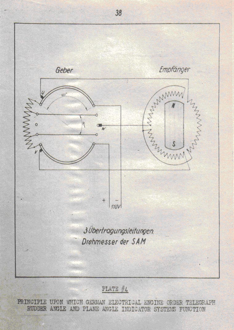
| Electrically, the system partakes of the principles incorporated in U.S. commercial D.C. syncro systems. The power supply is taken from the ship's 110 V D.C. regulated bus. Plate 3 delineates the schematic diagram upon which the system operates. In addition, a similar U.S. unit is described in "Electrical Engineer", June 1942. | ||
| The mechanical design of the components is worthy of detail study by those responsible for USN IC equipment design. Electrically, the use of D.C. for power on a submarine whose basic power is D.C. is noteworthy. The German application of a dummy impedance which is placed in the circuit upon actuating the receiver disconnect switch is a simple way to keep the circuit balanced. | ||
| b. Rudder Angle Telegraph System | ||
| This system is built in as part of the rudder angle indicating system. Its purpose is to provide an electrical system over which orders may be passed from the control room to the manual steering station in the after torpedo room. | ||
| The rudder angle indicator listed as being located in A.T.R. is mounted on the manual steering station in such manner that it is readily visible by the helmsmen. This receiver is provided with two dials, one of which indicates the actual rudder angle; the other indicating the rudder angle order set by the control room. The rudder order transmitter is incorporated in the Control Room rudder angle indicator with an external control lever. It is provided with two pointers, one to show the ordered angle, the other to show the actual angle. | ||
| The detail design and operating principle corresponds to that described under Engine Order Telegraph system | ||
- 22 - |
||
9C-S65 |
||
| c. Bow Plane Angle Indicating System | ||
| The design of the components and operating principle incorporated in this system corresponds to Rudder Angle Indicating System. The location of the components may be obtained from the chart shown at the beginning of this report on angle indicating systems. The scales are graduated to be read over 180 degrees of the dial units. The receiver located in the C.T. for the Bow and Stern Planes is contained in a small common housing with the stern plane receiver, thus presenting the position of both sets of planes for instantaneous viewing. No provision is made for cutting any of the receivers out of the circuit. | ||
| In addition, a complete system has been shipped to Naval Research Laboratory, Anacostia, D.C. for detailed exploitation and reference should be made to their report when it has been written. | ||
| d. Stern Plane Angle Indicating System | ||
| This system is similar to the Bow Plane Angle Indicating System. The location of the components may be obtained from the chart shown at the beginning of this report on angle indicating systems. | ||
| e. Mechanical Rudder Angle Indicating Systems | ||
| There are two separate systems installed for this purpose. Both are located in the A.T.R. | ||
| One consists of a worm driven nut on which a pointer is mounted. The nut operates from the steering shafting after the reduction gear box and clutch, thus providing a means of determining the rudder angle regardless of whether the steering system is manually of power operated. The longitudinal indicating scale over which the pointer travels is located between the Aft Torpedo Tubes suspended from the overhead. | ||
| The second system consists of a gear driven unit mounted directly on the manual steering station. It provides indication only when the steering plant is in manual operation. | ||
| f. Mechanical Bow Plane Angle Indicator System | ||
| This system is identical with the Teleflex systems installed in USN surface vessels in various applications | ||
- 23 - |
||
9C-S65 |
||
| and is so called by the Germans. Details of the system may be obtained from any Teleflex instruction book. | ||
| The German provided for power and manual operation of the diving planes in the Control Room with a clutch located in the forward room, so that when in use power, the shafting for manual operation is not in motion. | ||
| For this reason the Teleflex transmitter unit is located in the Forward Torpedo Room and is actuated by the bow plane shafting after it leaves the reduction gear box and clutch. The Teleflex cable is led from the transmitter to the indicator unit which is located in the Control Room at the diving station. | ||
| g. Mechanical Stern Plane Angle Indicator System | ||
| This system is identical with the Mechanical Bow Plane Angle Indicator system. | ||
| VII Engine Order Telegraph System | ||
| For complete system description, pictorial drawings and circuit diagrams, reference should be made to the German Instruction Book, "Beschreibung und Betriebvorschrift der Bu M Anlage", (Description and Operating Instructions for Interior Communication Systems). | ||
| In addition, a rudder angle system has been shipped to Naval Research Laboratory, Anacostia, D.C. for detailed exploitation, and while not altogether applicable to the Engine Order Telegraph System, the principles of operation are similar and reference should be made to their report when it has been written. | ||
| The system consists of a port and starboard installation which are not interconnected in any way, much the same as USN 1 and 2 MB circuits. No. 3 MB circuit is installed between the Engine Room and the Maneuvering Room. Thus, the Maneuvering Room does not become the Propulsion Control Center that it is on present design USN submarines. | ||
| The two systems are identical in every respect except for miscellaneous nameplates. The following comments are based on the individual system and may be applied to either port or starboard installation. | ||
| The components of a system are located as follows: | ||
- 24 - |
||
9C-S65 |
|||||||||||||||||||||||||||||
|
|||||||||||||||||||||||||||||
| A brief description of the components and operating principles of the system is set forth below. | |||||||||||||||||||||||||||||
| a. Transmitter Indicator Units | |||||||||||||||||||||||||||||
| The housings for all units are of cast aluminum alloy construction with the necessary tube terminals and connection boxes cast integral with the housing. The units are made watertight by means of socket type rubber gaskets. Captive screws with triangular heads are used throughout the system. | |||||||||||||||||||||||||||||
| The dial scales on the instruments are approximately seven inches in diameter zero center. The graduations are | |||||||||||||||||||||||||||||
- 25 - |
|||||||||||||||||||||||||||||
9C-S65 |
||
| placed on a white background - black figures for ahead, red for astern and green for stop. Illumination, the intensity of which is controlled by dimmer rheostat is provided only in the Conning Tower units. The dial faces are treated with relatively long persistence phosphorescent paint to aid in observing the pointer and graduations in event of a complete lighting failure. | ||
| All instruments are provided with annunciator type flags by means of which the operator may readily determine whether the power is on or off. | ||
| A common cover over the dial face and connection box is provided. A 5-1/2" plexi-glass window is provided to view the dial. The watertight seal is obtained by means of an O ring gasket. | ||
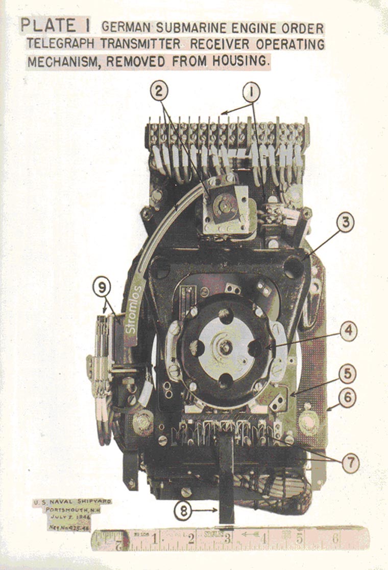
| The mechanical principles of design incorporated in the instrument are shown in plates 1 and 2 which delineate the working parts less the housing and dial. Attention is invited to the ease with which the complete assembly may be removed from the housing and with which any component on the assembly may be removed for maintenance or replacement without disconnecting the ship's wiring. | ||
| b. Transfer switches | ||
| These switches are of the type described in detail under General. They are enclosed in a watertight sheet metal housing, the cover of which is designed on the quick opening principle. The watertight seal is obtained by means of a socket type rubber gasket. | ||
| c. Signals | ||
| Buzzers of a standard type are installed in conjunction with the transmitting stations in the control room and are energized until the order is properly answered. | ||
| Motor driven horns in watertight housings provide an audible signal in the Engine Room and Maneuvering Room. These are energized until the order received is properly acknowledged. | ||
| The flashing light system consists of an inductance and a capacitance connected in parallel which act on a relay to make and break the associated lighting circuit 90 to 120 times per minute, thus insuring observation by the operating personnel. Steam lighting fixtures energized from the ship's 110 regulated D.C. are used. | ||
- 26 - |
||
9C-S65 |
||
| The port unit provided with a green globe while the starboard globe is red, thus corresponding with the colors used in the running light. This system is installed in the Engine Room only. | ||
| A corresponding visual signal is installed in the Maneuvering Room less the flashing light feature. | ||
| d. Connection Boxes | ||
| Fabricated sheet metal boxes are used throughout the system. The covers are provided with captive screws and the watertight seal is obtained by means of a socket type rubber gasket. | ||
| Terminal blocks of the type described under General are used throughout the system. | ||
| Relays and micro switches incorporated in the system are provided with parallel contacts to increase the reliability of the system. | ||
| Electrically the system partakes of the principles incorporated in U.S. commercial D.C. syncro systems. The power supply is taken from the ship's 110 V D.C. regulated bus. Plate 3 delineates schematically the principle upon which the system operates. In addition, a similar U.S. unit is described in "Electrical Engineering" June 1942. | ||
| The German instruction book indicates that each receiver requires 16.5 watts to operate it and that each transmitter is capable of satisfactorily driving 7 receivers. From the German installation and plans it is observed that he did not feel that the accuracy of the system required balancing of the load on the transmitter by substituting dummy impedances when cutting out a receiver as is the case in the Rudder Angle Indicating System. | ||
| From the installation of the transfer switches in the system, it would appear that the Maneuvering Room component is normally cut in when submerged and taking power from the battery or cut out when snorkelling or on the surface. Thus, under one condition of operation the Maneuvering Room answers the bells and in the other, the Engine Room answers them. If both rooms are cut in, then both rooms must answer before the audible or visual | ||
- 27 - |
||
9C-S65 |
||||||
| signal is de-energized in its compartment. | ||||||
| The German practice of providing a separate switch by means of which the signals associated with the system can be changed from visual to audible signals is an indication of the German's respect for minimizing noise under evasive tactics. In addition, the transmitter receiver units are mounted on bonded rubber mounts, mostly in sheer, to further decrease the noise transmitted to the hull. | ||||||
| VIII Aircraft Warning System | ||||||
| For complete system description and circuit diagrams reference should be made to the German Instruction Book, "Beschreibung und Betriebvorschrift der Bu M Anlage", (Description and Operating Instructions for Interior Communication Systems). | ||||||
| The purpose of the installation is to provide a manually operated audible signal (siren) system in certain compartments that aircraft is in the vicinity. | ||||||
| It consists essentially of four watertight motor driven sirens which are located one each as follows: | ||||||
|
||||||
| These sirens are energized from the ship's 110 V D.C. regulated bus by means of rotary snap switches located in the Control Room and Conning Tower. The switches are wired to provide for energizing in one compartment and de-energizing in the other or to energize and de-energize in the same compartment. | ||||||
| The associated connection boxes are fabricated from sheet metal with provision made for socket type rubber gaskets to maintain the watertight seal. The covers are secured with captive screws. | ||||||
| Terminal blocks of the type described under General are used throughout the system. | ||||||
| IX Diving Alarm System | ||||||
| For complete system description and circuit diagrams, reference should be made to the German Instruction Book, | ||||||
- 28 - |
||||||
9C-S65 |
|||||||||
| "Beschreibung und Betriebvorschrift der Bu M Anlage", (Description and Operating Instructions for Interior Communication Systems). | |||||||||
| The purpose of the installation is to provide a manually operated visual and audible signal system to warn operating personnel that the ship is about to dive or to surface. | |||||||||
| It consists essentially of seven watertight magnetically operated vibrator type bells which are located one each as follows: | |||||||||
|
|||||||||
| In parallel with the Engine Room and Maneuvering Room bells, a visual system is installed to insure attention is drawn to the alarm signal. This portion of the system operates as follows. The compartment illumination circuit is led into a relay, the coil of which is energized through the normally closed contacts of an inductance capacitance type vibrator which in turn is only energized when the alarm system is energized. Thus, when the alarm circuit is energized, the compartment illumination flashes on and off at a rate of approximately 90-120 times per minute. | |||||||||
| The system is energized from the ship's 110 V regulated D.C. bus. The control points are the C.T. and C.R. Rotary type snap switches are used for this purpose and provision is made for energizing at one compartment and de-energizing at the other compartment. | |||||||||
| The components are of watertight construction, being manufactured from cast aluminum, fabricated sheet metal and the necessary other materials. Watertight seals are of either O ring design or socket type rubber gaskets. Terminal blocks used throughout the system are of the type described under General. | |||||||||
| The German use of a flashing compartment illumination system at points of high noise intensity in conjunction with the diving alarm system is noteworthy. | |||||||||
- 29 - |
|||||||||
9C-S65 |
||
| X Hull Closure Indicating System | ||
| XI Vent Valve Indicating System | ||
| XII Exhaust Gas Valve Indicating System | ||
| XIII Compartment Ready Indicating System | ||
| For complete description and circuit diagrams of the above systems, reference should be made to the German Instruction Book, "Beschreibung und Betriebvorschrift der Bu M Anlage", (Description and Operating Instructions for Interior Communication Systems). | ||
| The systems are comprised of suitably located switches, contact makers, connection boxes, and indicating lamps for the purpose of informing the diving station in the control room of the condition of the various valves, hull openings other then hatches and compartment doors with regard to readiness for diving or surfacing. | ||
| The power supply for all the systems is obtained from the ship's 110 V regulated D.C. bus. The various housings for the components are made drip-proof or watertight in accordance with German practices. Indicating lamp boxes are generally made drip-proof employing hat type ventilators. | ||
| The indicating lamps are not grouped in a common housing to provide for easy viewing but each system is provided with its own separate indicating lamp box which is frequently located 18 to 24 inches apart. | ||
| XIV Salinity Indicator System | ||
| For complete description, pictorial drawings and circuit diagrams of the system, reference should be made to the German Instruction Book, "Beschreibung und Betriebvorschrift der Bu M Anlage", (Description and Operating Instructions for Interior Communication Systems). | ||
| The salinity indicators are installed in conjunction with the distilling units to determine the salt content of the distilled water between 30 and 100 milligrams per liter. | ||
| Electrically, the system corresponds in general with the type installed by USN SS169 (USS DOLPHIN) with the following exceptions. | ||
- 30 - |
||
9C-S65 |
|||||||||||||
| The operating voltage used on the electrodes is 62 volts 50 cycle A.C. The resistance thermometer which forms one leg of the bridge is designed so that its change in resistance due to changes in temperature corresponds to changes in conductivity of the water due to changes in temperature, thus tending automatically to keep the system in balance and minimizing errors due to this source. The milliammeter used in the circuit is energized from direct current obtained by rectifying the A.C. The system is reputed to be accurate over water temperatures of 0° to 100°C. | |||||||||||||
| Physically the units are well designed for the purpose intended. The electrodes and resistance thermometer are assembled on a common screw-in plug which is installed at the desired test point. Except for the indicator unit, the other components, transformers, resistances, etc. are mounted in a common fabricated sheet metal watertight housing. | |||||||||||||
| XV Diesel Engine Torsional Vibration Indicator System. | |||||||||||||
| For a complete system description, pictorial drawings and circuit diagrams, reference should be made to the German Instruction Book "Beschreibung und Betriebvorschrift für die Dieselmotoren M9 V40/46C und M9 V40/46 CB auf den Unterseebooten Bauart IX C und IX D2 Band 1", (Description and OPerating Instructions for the Diesel Engines M9 V40/46 C and M9 V40/46 CB for U Boats IX C and IX D2 Volume 1). | |||||||||||||
| In addition, systems have been shipped to the below-listed activities for detailed exploitation, and reference should be made to their reports when they have been written. | |||||||||||||
|
|||||||||||||
| The systems are installed in the Engine Room, one for the port engine and one for the starboard engine. | |||||||||||||
- 31 - |
|||||||||||||
9C-S65 |
||
| A system consists essentially of a transmitter, a combination control and connection box and an indicator unit. | ||
| The transmitter unit is coupled directly to the engine crankshaft at the forward end and is designed to supply three indicator units. | ||
| The control and connection box is mounted on the bulkhead adjacent to the transmitter unit and consists essentially of a fabricated sheet metal housing with a watertight cover. In it are mounted the adjusting component for calibrating the system, necessary terminal boards of the type described under General, the equivalent dummy impedances for use when less than three indicator units are in use, and a means for connecting or disconnecting these impedances. | ||
| The indicator unit is a millivolt meter whose scale is graduated to be read between zero and 1.3 degrees. A point on the scale indicates the limit beyond which it is unsafe to operate the engine at that speed. | ||
| The system is installed to serve as a means of determining the effectiveness of the vibration damper installed. No external power supply is required. | ||
| A brief description of the principle upon which the system is based is presented as follows. In effect, an A,C, generator is coupled directly to the shaft to provide a voltage to actuate the millivolt meter indicator unit. | ||
| The armature of the generator is coupled directly to the Engine crankshaft and follows its motions accurately. The magnetic field which is relatively large is coupled to the Engine crankshaft by means of a flexible torsional spring and is separated from the armature by means of roller bearings. When there is no unbalance in the system, the armature and magnetic field travel concentrically with each other in synchronism. As soon as torsional unbalance occurs, the armature follows the motion of the crankshaft and the magnetic field due to the flexible connection and its mass inertia tends to keep in motion at a uniform angular speed. Thus, the differential in angular motion between the armature and field generates an A.C. voltage which is proportional to the angular displacement and the frequency of the unbalance vibratory force. The influence of the vibration frequency is compensated for by means of the flexible coupling unit so that the generated A.C. output voltage becomes a function of | ||
- 32 - |
||
9C-S65 |
||
| only the angular displacement. | ||
| In order to avoid inaccuracies due to brushes and slip rings for removing the A.C. voltage from the armature, a special coupling transformer is used. The primary of this transformer is mounted on the rotating magnet frame at the end opposite the armature. It rotates with the magnetic field and its input is connected to the output of the armature. The secondary winding remains stationary and is separated from and supported by ball bearings from the rotating system. It is supported externally at the cable entrance. Thus, any voltage generated in the armature is fed into the rotating primary of the transformer coupling which in turn energizes the stationary secondary winding. The output of the secondary winding is fed through the combination control and connection box to the indicator unit. | ||
| XVI Temperature Indicating Systems | ||
| These systems are installed in conjunction with lubricating, cooling water and exhaust gas temperatures on the main engines and motors. | ||
| For complete description, pictorial drawings and diagrams, reference should be made to the following German Instruction Books. | ||
| "Beschreibung und Betriebvorschrift für die Dieselmotoren M9 V40/46C und M9 V40/46 CB auf den Unterseebooten Bauart IX C und IX D2 Band 1", (Description and OPerating Instructions for the Diesel Engines M9 V40/46 C and M9 V40/46 CB for U Boats IX C and IX D2 Volume 1). | ||
| "Beschreibung und Betriebvorschrift der E. Antriebanlage U Boote Typ IX C 40." (Description and Operating Instructions for the Electrical Operating System in U Boats Type IX C/40). | ||
| These systems are comprised of the necessary pyrometers, thermometers and indicator units necessary for measuring the temperatures of air, water, oil and exhaust gases at the selected points on the Diesel engines and main motors. The systems are not as elaborate nor are as many points checked as in USN propulsion installations. It is observed that alarms are not installed with any of these systems. | ||
| It is interesting to note that individual temperature indicators are supplied for each cylinder on the diesel engines and, in addition, one in each duct into which three cylinders exhaust. Present U.S.N. practice utilizes one | ||
- 33 - |
||
9C-S65 |
|||||||||||||||||||
| indicator unit with provision for a selector switch. | |||||||||||||||||||
| XVII Voice Tube System | |||||||||||||||||||
| For system layout, reference should been made to the German "Skizzenbuch Band M Bauart IX C", page 35 (Sketch book Volume M, Type IX C). | |||||||||||||||||||
| The German used the voice tube as a means for communication to a much greater extent than it is used in current design USN submarines, but rather corresponds to the type of installation made in the "S" boats. | |||||||||||||||||||
| Four separate systems are installed with the Control Room and/or Conning Tower being the focal points. These systems are installed as follows: | |||||||||||||||||||
|
|||||||||||||||||||
| From German plans of all systems available here, it appears that the only means of communication between the Sound Room, the Radio Room and the Conning Tower, Control Room or Bridge is by means of the Voice system. | |||||||||||||||||||
| Systems 2 and 3 are cross connected in the Conning Tower by means of flexible metal hose. | |||||||||||||||||||
- 34 - |
|||||||||||||||||||
9C-S65 |
||||||
| All terminals are provided with spring loaded hinged covers at the mouth piece which must be lifted clear before using the system. | ||||||
| The portable units are connected to the fixed tube by means of flexible metal hose, the length varying between 4 to 8 feet to suit the installation. | ||||||
| Seven petcocks are installed in the Control Room to provide a means of securing any one line from flooding the compartment. Two similar petcocks and a drain line are installed between the Bridge and the Conning Tower. Torpedo Rooms may be secured in a similar manner. | ||||||
| The diameter of the piping used for the most part throughout the systems is 2-1/8 O.D. and 1-3/4" I.D. The piping was galvanized iron and as installed, it would appear that no attempt has been made to avoid sharp radii. In many cases, branch circuits are welded to the main circuit at very sharp angles. The joining of the two is by means of arc welding and as nearly as can be determined no attempt was made to clear the inside of weld beads. | ||||||
| XVIII Marker Buoy System | ||||||
| For complete system description and drawings, reference should be made to the German Instruction Book, "Beschreibung un Betriebvorschrift der Secherheitseinrichtungen U Boot Typ IX D2", (Description and Operating Instructions for the Escape Hatches and Emergency Life Rafts Submarines Type IX D2). | ||||||
| A major difference between USN Marker Buoy Systems and German Systems lies in the fact that the German System does not provide either a visual or an audible communication system. | ||||||
| As in USN submarine wartime practice, the Germans did not install their systems. | ||||||
| Four units are installed, one each to be actuated from the following compartments: | ||||||
|
||||||
| Briefly, each buoy consists of a multicell, chemically self inflating life raft on which is mounted a colored buoy. Hand grips are provided around the outer edge for | ||||||
- 35 - |
||||||
9C-S65 |
||
| those who must remain in the water. Pockets are provided which contain copies of ship's papers, signal flags, and signal gun with ammunition. | ||
| The raft is folded tear shaped to fit in pressure-proof stowage which is securely attached to the hull. The cover of the stowage is designed on the breech type used throughout the vessel and is presumably self-opening by means of a spring when the pressure is equalized within the stowage. | ||
| Provision is made within the vessel at each location for the following operations: | ||
| 1. A mechanical gear arrangement for disengaging the breech ring on the stowage. | ||
| 2. A drain valve for checking the watertight integrity of the stowage. | ||
| 3. A flood valve for equalizing water pressure within stowage with sea pressure. | ||
| 4. A valve for applying compressed air to the stowage to insure buoy leaves stowage. | ||
| Each buoy is provided with approximately 375 feet of line. No means is provided for lubrication of mechanical parts of the system from within the vessel. | ||
| Conclusions | ||
| The German I.C. installations are of simple and rugged design and by no means elaborate. The uniformity of the installations from vessel to vessel, and for that matter from type to type, indicates that the German believed he had attained all that was necessary in these installations for successful operation. | ||
| On the whole, the simplicity of the installations and the location of the components leads one to observe that considerable reliance was placed on the operating personnel, both in normal operations and when making an attack. | ||
| Noteworthy of the systems are the following factors: | ||
| 1. The use of regulated D.C. power for large percentage of his installations. | ||
| 2. The presentation of the systems in relatively composite instruction books both from a training and a maintenance viewpoint. | ||
| 3. The thoroughness which the German applied himself to small design details with their attendant desirable effects on manufacture and procurement. | ||
- 36 - |
||
9C-S65 |
||
| For additional information with regard to the relative merits of the individual systems, reference should be made to the reports written by the exploiting activities referenced when they become available. | ||
| Interrogation of USN personnel who operated and are operating different types of German submarines indicates that no maintenance, except routine, has been necessary up to the time of this writing. | ||
- 37 - |
||
9C-S65 |
||
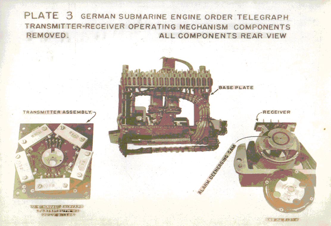
| PLATE #1 GERMAN SUBMARINE ENGINE ORDER TELEGRAPH TRANSMITTER RECEIVER OPERATING MECHANISM REMOVED FROM HOUSING | ||
| 1. Terminal Boards Described under "General". | ||
| 2. Annunciator type Power Indicator and Actuating Relay. | ||
| 3. Receiver Supporting Frame. | ||
| 4. Receiver D.C. Selayn Type. | ||
| 5. Transmitter Assembly. | ||
| 6. Base Plate. | ||
| 7. Hinged Plug Type Connection Block (Female) Assembly. | ||
| 8. Contact Looking Device (Engages on Housing). | ||
| 9. Alarm Relay and Contacts (Contacts for Energizing Controlled by Matching Receiver and Transmitter). | ||
- 38 - |
||
9C-S65 |
||
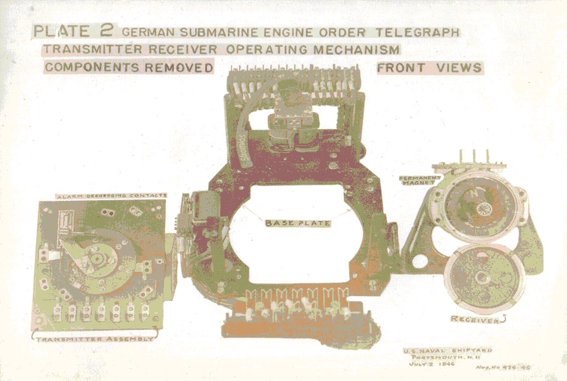
| PLATE #2 GERMAN SUBMARINE ENGINE ORDER TELEGRAPH TRANSMITTER-RECEIVER OPERATING MECHANISM COMPONENTS REMOVED. ALL COMPONENTS FRONT VIEW | ||
| FOR IDENTIFICATION OF COMPONENTS SEE PLATE #1 | ||
- 39 - |
||
9C-S65 |
||
| PLATE #3 GERMAN SUBMARINE ENGINE ORDER TELEGRAPH TRANSMITTER-RECEIVER OPERATING MECHANISM. ALL COMPONENTS REAR VIEW. | ||
| FOR IDENTIFICATION OF COMPONENTS, SEE PLATE #1 | ||
- 40 - |
||