|
|||||
FORMER GERMAN SUBMARINE TYPE IX-C |
|||||
FUEL OIL STOWAGE AND EQUIPMENT |
|||||
SUMMARY |
|||||
| The fuel oil stowage facilities and piping arrangements on the IX-C submarines contain numerous design differences and are in many details simpler than the installations on U.S. submarines. | |||||
| The tankage layout if different in that four of the fuel tanks lie within the pressure hull and that two of the variable ballast tanks are fitted for carrying fuel. No expansion tanks are provided; however, their function is accomplished by small salt water compartments in the lower sections of the normal fuel tanks. The functions of the collecting tank and clean oil tank are accomplished by the two gravity feed tanks located in the engine room overhead. | |||||
| Filling of oil tanks and transfer of oil from storage tanks to the gravity feed tank is accomplished through a manifold arrangement. Test pressures on inboard piping is limited to 28.4 psi. Pumping arrangements are provided with portable connections to the lub oil transfer pump. | |||||
| Fuel oil purification is dependent upon settling and filtration processes; no purifiers are installed. To detect water in the oil of dirty oil, numerous sight glasses and settling gauges on sampling lines are installed. | |||||
| The fuel oil service arrangements are essentially similar to those on U.S. submarines. However, no permanently connected standby pump is provided; the functions of the latter are for the most part accomplished by the gravity head on the feed tank. It is also possible to use the lub oil transfer pump on the service system, if necessary | |||||
June, 1946 |
|||||
PORTSMOUTH NAVAL SHIPYARD, PORTSMOUTH, N. H. |
|||||
- 1 - |
|||||
9C-S55 |
||
C O N F I D E N T I A L |
||
FUEL OIL STOWAGE AND EQUIPMENT |
||
| 1. GENERAL DESCRIPTION | ||
| The fuel oil systems on the IX-C German submarine have been set up to service two, comparatively slow speed, diesel engines; the tank capacities are such as to provide a maximum cruising range of approximately 13,500 miles. The piping and plumbing arrangements with the service and transfer systems are for the most part kept simple. Some additional emergency service is provided through use of numerous portable hose and pipe connections to other piping systems. | ||
| The IX-C can carry but a small percentage of its total fuel capacity in the normal fuel tanks. Four of the normal fuel tanks are outside of the pressure hull and four, of less capacity, are inboard. The remaining capacity is carried in the eight fuel ballast tanks and in the two variable ballast tanks fitted to carry fuel oil. In each case port and starboard tanks are considered as individual tanks. | ||
| A compensating water system is used with all fuel carrying tanks with the exception of the auxiliary tanks. Pressure on the compensating system is through the medium of a head box in the superstructure. The compensating lines to the individual fuel ballast tanks run directly to the bottom of the tank while the line for the outboard normal fuel tanks leads into the small salt water niche (1.5% of fuel tank's volume) in the bottom of the tank; a line then leads from the top of the niche to the bottom of the fuel tank. The main compensating line to the inboard tanks feeds a distributing manifold that has individual lines running to the bottom of the tanks. Safety valves with leak-offs to the bilge are on both the branch line to the manifold and the manifold. All tanks have the necessary inboard vents, backed up by two valves. Test piping with an overboard discharge leads from the bottom of all the normal fuel tanks, and from a point approximately 4 inches above the top of the flood opening on the fuel ballast tanks. These test lines are normally used as salt water discharge lines when fueling - not only to indicate when the tank is filled with oil - but mainly to prevent possible contamination of the compensating water lines with fuel oil. All piping runs external | ||
- 2 - |
||
9C-S55 |
||
| to the pressure hull. | ||
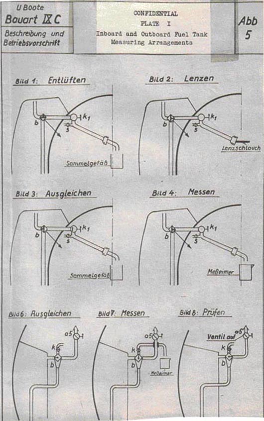
| A simple yet accurate, type of measuring arrangement is installed on one of the outboard and on both starboard inboard normal fuel tanks. The principle on which this operates can be obtained from reference to plate 1. On sketch 3, cock b is set to equalize the oil level in both the measuring line and the tank. Then changing the cock to the position shown in sketch 4 permits draining off of the oil in the standpipe into a measuring glass, which when properly calibrated gives a true measurement of the oil within the tank. | ||
| The fuel piping arrangements on the variable ballast tanks that carry fuel are designed so that while removing all of the fuel oil from the tank it is only necessary to compensate for half of the tank's capacity. The port and starboard tanks are interconnected; the oil suction line on the starboard tank is at the tank's bottom while the line on the port side is about 3-1/2 inches above half tank capacity. On emptying half of the tank, water is then led in to again fill the tank; then the remaining oil is led off through the port suction line. A by-pass relief is on this piping to prevent excessive pressures being put on the transfer line; in addition, a small inboard venting connection is fitted so that excessive pressures can not get on the transfer piping (because of leaky valves) when the variable ballast tank is used for compensating purposes. | ||
| A portable hose connection has been fitted on one of the outboard normal fuel tanks to provide a means for pumping out the contents of the tank; no fitting, however, has been provided to permit the use of air in this regard although it was originally contemplated. | ||
| Conversion of six of the eight fuel ballast tanks to main ballast tanks is accomplished from inboard. All valves on the outboard vent lines, compensating lines and fuel lines are operated from inboard. Blank flanges are not used on the main vent lines. | ||
| The transfer of fuel oil is accomplished through a manifold arrangement. Individual manifolds servicing two tanks are located inboard of the fuel ballast and outboard normal fuel tanks. The inboard fuel tanks and the variable ballast tank fitted for carrying fuel, however, have individual cut-outs. (Back-up valves are installed on all piping leading inboard from the outboard fuel tanks.) Two main fuel oil manifolds are located in the engine room. One acts as a central fuel tank manifold and the other acts as a main distributing manifold. The latter receives oil from | ||
- 3 - |
||
9C-S55 |
||
| the tank manifold and discharges it either directly to the gravity feed tanks, via a fuel oil meter, or via the lub oil transfer pump. Wire mesh strainers are situated on the suction side of the meter and in the transfer piping leading directly to the gravity feed tank. A four-way cock is used on the connection to the feed tanks which lines up one tank for filling and at the same time lines up the other with the fuel oil service piping. A special test connection and a sampling connection are on the line leading to the feed tanks. A portable pipe can be used to by-pass the feed tanks so that oil can be fed directly to the service piping from the storage tanks. | ||
| Emergency pumping of fuel oil with the use of the hand cooling water pump is provided. A selector valve is fitted on both the suction and discharge sides of this pump to permit it to be used directly with the transfer piping. | ||
| The capacity of the gravity feed tanks is appreciably less than the capacity of clean oil tanks on U.S. submarines. The tanks have overflow pipes, drainage lines and sampling lines with standpipes (to detect water in the oil); all of these lines have leads to a small fuel oil pump tank. One tank is used to furnish oil to the main fuel pumps while the other acts as a settling tank. This operation is switched when the "service" tank is emptied and is refilled. | ||
| The layout of fittings and pumps in the service piping is for the most part similar to U.S. practice. The main difference lies in the provision of a fuel oil meter and in the installation of a sampling line with a sight glass on the fuel pump's suction. The fuel oil is led from the gravity feed tank through the meter (or its by-pass) to either or both attached feed pumps from where it is delivered through a knife-edge filter to the individual cylinder fuel pumps. The attached feed pumps can be by-passed; also, a pressure relief valve and a safety valve are fitted on the pump's discharge piping. All leak-off oil from the diesel engine as well as from the sampling lines leads to the fuel sump tank. | ||
| The fuel oil meter used is of particular interest. Inasmuch as the same type of meter is used for other services as well, it has been described under the S48 section of the IX-C report. | ||
| A separate system is set up to service the Junkers compressor. Oil is fed by gravity from the gravity feed tank to a small Junkers service tank. A fuel pump then takes its suction from this tank to feed the Junkers. A by-pass is installed around the tank so that the Junkers fuel pump can | ||
- 4 - |
||
9C-S55 |
||||||||||||||||||
| take a suction direct from the diesel engine service piping. | ||||||||||||||||||
| 2. INDIVIDUAL COMPONENTS | ||||||||||||||||||
| a) Fuel oil tanks | ||||||||||||||||||
|
||||||||||||||||||
| b) Fuel oil service pump (attached) | ||||||||||||||||||
|
||||||||||||||||||
| c) Filters | ||||||||||||||||||
|
||||||||||||||||||
| d) Fuel oil meters | ||||||||||||||||||
|
||||||||||||||||||
| e) Fuel oil piping | ||||||||||||||||||
| 1. Annealed steel characteristics | ||||||||||||||||||
|
||||||||||||||||||
| 2. Test pressures | ||||||||||||||||||
|
||||||||||||||||||
- 5 - |
||||||||||||||||||
9C-S55 |
||
| 3. CONCLUSIONS | ||
| From an overall standpoint the fuel oil system and stowage arrangements on the IX-C do not provide for the continued reliability and safety of operation as well as is provided on the U.S. submarines. Much additional reliance on observations by operating personnel is required to insure that the engines do not receive oil contaminated with water. The possibility of leaving oil slicks through the medium of the compensating water system, although not readily possible, is more probable with the German arrangement. Emergency and standby arrangements, although provided, require much additional time and work to be placed in operation than is required on U.S. submarines. | ||
| Several details of the system, however, are of particular note. The fuel oil meters are an improvement over U.S. designs. The simple tank capacity measuring device requires little piping and at the same time indicated actual contents whereas the one on U.S. vessels gives approximate contents while using much additional piping. The small fuel oil sump tank that is used as a collecting agent from all relief valves, sampling lines, etc. is of merit. The salvage tank on U.S. submarines performs this function to a lesser degree. | ||
- 6 - |
||