86. |
||
CHAPTER III |
||
The principal purpose of the Sea Search Attack Group was to provide the flying facilities and supervision of personnel and equipment assigned to it in order to accomplish most effectively the development of the tactics and techniques and training of combat crews and technicians so that the devices undergoing tests could best be utilized in actual search and attack upon enemy submarines and surface craft. |
||
There is no doubt that the critical U-boat situation which prevailed on the Eastern Coast during the early part of 1942 had a decided influence on the decision to form such a Sea Search Attack development Unit, but the practical advantages of this type of organization were also apparent. With the nation recently plunged into war, great speed was urgently needed in the development of new and as yet untried airborne devices which had only just started to emerge from their laboratory cocoons. By placing this organization under the direct control of the Commanding General, Army Air Forces, a great amount of valuable time was saved and much red tape and routine procedure eliminated. |
||
87. |
||
Quick reliable, and unbiased answers were wanted in order that decisions could be made with the least possible delay. |
||
The record of the 1st Sea Search Attack Group as a test and development unit is impressive, even though the period of activity covered by this report extends only from 17 June 1942 to 15 July 1943. It should be remembered that Sea Search started from scratch. A completely new organization had to be welded together into an efficiently operating unit, and for the most part the men and officers available were inexperienced. However, enthusiasm, hard work, and good leadership combined to overcome these difficulties; and upon receipt of the necessary planes, equipment and personnel, the testing program was launched. |
||
Of a total of 62 projects assigned to this Group, 44 were actively carried on and 36 completed prior to 15 July 1943. The two most comprehensive projects were SS #7 MAD and SS #10 ASV; and, while these two represent a major portion of the effort expended by the 1st Sea Search Attack Group, all other projects received an appropriate amount of test and development effort commensurate with a true evaluation of their individual importance and needs. |
||
In examining the following summary of project activity, it will be noted that several were proposed but no action taken. In most instances the reason for this was that some other device was determined to be superior or that after carefully investigating it was recommended that the proposal be dropped as impractical. |
||
88. |
||
On the other hand several projects had associated activities, such as the submarine simulator coil and MAD high altitude tests which were carried on in connection with regular MAD Mark IV and Mark VI projects. It should also be noted that various types of ASV Radar were successively tested under SS #10 including MIT 517A, 517C, 717A, 717B, and ASG. |
||
It is, of course, impossible to discuss in appropriate detail each of the sixty-two projects. Therefore each will be summarized in this history, but by consulting the bibliography at the conclusion of the history, the reader desiring more complete and technical information will find reference to a series of envelopes containing Project Final Reports, photographs, blueprints, pertinent correspondence, etc. These envelopes have been placed in the hands of the Army Air Forces Historian. |
||
To the conduction of these projects, the Search devoted 25 percent of its flying time (or 2497 hours) between June 22, 1942 and July 15, 1943. Many more hours were employed on the ground by both civilians and Search personnel in furthering these projects.* |
||
The two key men in the project work were Captain Frank R. Dickey (Group Radar Officer) and Mr. Norman D. Webster of Columbia University who after some months with the Search was commissioned a Major and assigned to the Group. Major John R. Freeman was Project Coordinator. The civilians who worked on these projects needed no encouragement; they had to be held back, for facilities were limited and all wanted high priority. They were eager. A summary of each project follows. |
||
- - - - - - - - - - - - - - - - - - - - - - - - - - - - - - - - - - - - - - - - - - - - - - - - - - - - - - - - - - - - |
||
* An analysis of project time appears in Appendix 24. |
||
89. |
||
SS #1 - MAGNETOMETER, AIRBORNE GYRO STABILIZED |
||
This project was initiated on July 7, 1942, for the purpose of testing a gyro-stabilized magnetometer developed by General Electric Laboratories. Plans were formulated for conducting tests on this device in September, 1942, however, no testing was accomplished at this headquarters due to the fact that the equipment was superseded by Columbia Laboratories' MAD Mark IV. The Columbia MAD was superior because it made use of a magnetic stabilized magnetometer. SS #1 was closed out on November 20, 1942. |
||
SS #2 - MAGNETOMETER, AIRCRAFT |
||
This project was set up on July 3, 1942, for the purpose of testing an aircraft magnetometer developed by Sperry Gyroscope Company. No actual testing took place at this headquarters, since the Columbia Laboratories' MAD possessed a greater range and was considered more satisfactory. SS #2 was closed out on November 20, 1942. |
||
SS #3 - DIRECTIONAL MICROPHONE |
||
No active testing took place at the 1st Sea Search Attack Group in connection with this project, which was set up on 3 July 1942. |
||
90. |
||
Preliminary testing using a helicopter in conjunction with a directional hydrophone was accomplished by Wright Field, October, 1942. Plans were under way for conducting tests on a helicopter at this Group in order to determine its usefulness in the field of antisubmarine warfare and what antisubmarine equipment it should possess. |
||
SS #4 - MORTAR PROJECTION OF FLARE |
||
Work on this project began on July 4, 1942, and concerns the use of a 60 MM. infantry mortar illuminating flare projected forward from the aircraft's upper rear turret for the purpose of identifying a target. Construction of a suitable 60 mm. mortar was accomplished at Rock Island arsenal. This mortar differed from the standard 60 mm. mortar since it contained a longer tube; an installation to absorb forces of recoil; and could be opened at the rear for loading and installation of a firing mechanism. Subsequent ground tests at Aberdeen Proving Grounds with the mortar installed on a B-18 proved satisfactory. Flight tests on November 16th at Langley Field showed that slight modification of the mortar support would be necessary. A modified mortar was ground and flight tested at Aberdeen on December 17th, after which it was decided to change the angle of fire. Investigation of mortar and projectile characteristics was also being carried out. Lack of ammunition delayed any further testing, and it was finally decided that, since the immediate problem was being solved by a searchlight (SS #55), the project |
||
91. |
||
should be dropped. Authorization to close out this project is contained in a letter of April 6, 1943, subject: "Closing out of Project SS #4, Mortar Projection of Flare" from Mervin E. Gross, Colonel, A. C. |
||
TEST DATA |
||
Tests: |
||
No. of flights - 4 Total flight time - 10:55 |
||
No. of ground tests - 2 Total ground time - 4:30 |
||
Installation of equipment: |
||
No. civilian man hours - 10:00 No. plane hours - 10:00 |
||
Instructions: None |
||
Total hours planes used on project: 25:25 |
||
Total man hours expended in installations and instructions: 10:00 |
||
No. Rounds of ammunition fired: |
||
On ground tests - 16 On flight tests - 27 |
||
SS #5 - LOW ALTITUDE RADAR ALTIMETER |
||
| The AYB-1 altimeter operates on the Radar reflection principle, ranging from 0 to 400 feet from ground level, using a frequency modulated transmitter and a balanced detection system feeding into specialized pulse shaping circuits activated by the beat frequency difference between the transmitter and received signals. Altitude indications are given on a direct reading D.C. millimeter calibrated in feet of altitude which | ||
92. |
||
is actuated by the cathode current flowing in a 12SR7 tube used as an altitude indicating amplifier. |
||
One AYB altimeter was installed in a B-18 assigned to the Sea Search Attack Group, and tests to determine the accuracy of this altimeter under service operating conditions were started on 16 October 1942 in conjunction with the NACA, as requested by the Director of Technical Services. Tests performed included flight tests of altitude indications checked photographically in the plane and fro the ground while the plane was flying over a measured course. Bench tests were also conducted to determine the consistency of altitude indications when the power supply voltage was varied. |
||
The results of these tests were favorable, and it was concluded that the AYB-1 altimeter altitude indications are reliable within six feet from 0 - 400 feet. |
||
However, maintenance problems were encountered due to the fact that necessary bench testing equipment was not available. |
||
Three AYB-1 altimeters were installed in B-18's assigned to the 1st Sea Search Attack Group, and it may be stated that, provided proper maintenance is accomplished, these altimeters will operate satisfactorily. |
||
93. |
||
Test Data |
||
Tests: |
||
No. of flights - 12 Total flight time - 14:45 |
||
No. of ground tests - 2 Total ground time - 9:00 |
||
Installation of equipment: |
||
No. military man hours - 34:00 No. plane hours - 7:00 |
||
Instructions: None |
||
Total hours planes used on project: 30:45 |
||
Total man hours expended in installations and instructions: 34:00 |
||
SS #6 - MAGNETIC TRAWL |
||
This project was set up on 4 July 1942, to cover testing of a magnetic trawl which was being developed by Aircraft Radio Laboratories, Wright Field. Results of experimentation of Wright Field subsequently indicated that the original design for the trailing cable type of MAD was impracticable and further study would be necessary. No actual testing was accomplished at Langley Field, and the project was closed out on 23 July 1942. |
||
SS #7 - MAD MARK IV-B2 |
||
Mark IV-B2 MAD equipment was developed by Columbia University Laboratories under the auspices of NDRC. The first units were tested at Mitchel Field, New York, and upon the activation of the Sea Search Group this project was initiated, and testing was then accomplished at Langley Field. |
||
94. |
||
Mad Laboratory |
||
On 1 July 1942, work was commenced to establish a MAD Laboratory and Shop in the 2nd Sea Search hangar at Langley Field. Civilian personnel, headed by Mr. Norman Webster (later Major Webster of the Search) laboratory instruments, and tools were supplied by the Columbia University NDRC Group. Competent service mechanics were furnished from the 2nd Sea Search Squadron. This laboratory was also made available to projects other than MAD where the skilled mechanics, machine tools, test instruments, and large stock of electronic equipment was extremely valuable. |
||
MARK IV-B2 Capabilities |
||
The MAD magnetic airborne detector is a device for detecting submerged submarines from airplanes. It also detects other large bodies of metal, such as shipwrecks or large underground installations containing an appreciable amount of iron or steel. Its range depends on the magnetic characteristics of the submarine or other target being sought and extends from approximately 600 feet on a submarine to 15,000 feet or more on large buildings of shipyards.* Water in the path between airplanes and target has no effect on the range of MAD. The equipment produces a continuous trace on a moving tape. During operation any change in the earth's field caused by the presence of a magnetic body |
||
- - - - - - - - - - - - - - - - - - - - - - - - - - - - - - - - - - - - - - - - - - - - - - - - - - - - - - - - - - - - |
||
* Appendix 25 contains a report to General Arnold concerning MAD tests over cities. |
||
95. |
||
will cause an excursion of a recording pen across a moving paper tape, making a permanent record of any signal received. |
||
Searching for enemy submarines with MAD is only practical if the position of the submarine is approximately known. This is true since the maximum sweep path of MAD would be approximately 800 feet wide and 100 feet deep for an airplane flying at an altitude of 200 feet above the water. Only approximately 20 square miles could be swept out per hour at an airplane speed of 120 m.p.h. |
||
Once a submarine is approximately located by radar or other means and then submerges, the MAD equipment serves to accurately locate and track the submarine.* |
||
A submarine or other magnetic body which is to be detected may be assumed to be a large magnet or "magnetic moment". The field that the MAD detects is the superposition of this field on that of the earth. The MAD detects any change in the earth's field. |
||
The Mark IV-B2 MAD equipment will detect a change of two parts in 60,000 while being carried in an airplane in flight. The earth's field in the Langley Field area is approximately 58,000 gammas along a line parallel to its maximum. A change in this field of 2 gammas may easily be detected while in flight. |
||
- - - - - - - - - - - - - - - - - - - - - - - - - - - - - - - - - - - - - - - - - - - - - - - - - - - - - - - - - - - - |
||
* See Appendix 26 for tactical procedure for B-18 airplanes equipped with Mark IV MAD. |
||
96. |
||
The detector element of this equipment is normally carried in the large cone of "stinger" attached to the tail of the airplane. The electronic apparatus and signal indicators are located near the radar operator's platform or position. |
||
Mark IV-B2 Installation |
||
Between 1 July and 1 September 1942, five of the first Mark IV-B2 MAD installations were made in B-18 airplanes in the 2nd Sea Search hangar. Many other installations made at San Antonio Air Depot were flight tested and shaken down at Langley Field. |
||
MAD Training |
||
One hundred and nineteen MAD operators were trained by Sea Search in the use and operation of Mark IV-B2 MAD. The larger part of the classroom work was conducted by A.I.L. instructors. The students were checked off on MAD in the AIR by Army personnel. |
||
Eleven mechanics were trained by A.I.L. engineers at Sea Search to service and repair Mark IV-B2 and Mark VI MAD equipment. These mechanics in turn gave instruction to enlisted personnel in the 12th and 18th Antisubmarine Squadrons in both operating and servicing technique. Thirteen civilian Civil Service Signal Corps engineers were trained in the theory, maintenance, and operation of Mark IV-B2 MAD equipment. This training was carried on in the MAD Laboratory by A.I.L. engineers.* |
||
- - - - - - - - - - - - - - - - - - - - - - - - - - - - - - - - - - - - - - - - - - - - - - - - - - - - - - - - - - - - |
||
* Training of a less technical nature was given to Pilots, Co-pilots, Navigators, and Bombardiers. See Appendix 27 for lecture outlines. |
||
97. |
||
Magnetic Compensation |
||
There are many steel parts in an airplane, such as motors, control cables, landing gear, rudder part, etc. These parts are often permanently magnetized, and their magnetic characteristics change with heading, which results in a change in the direction of the earth's field acting on them. Such magnetism in the airplane causes interference with MAD equipment, and these magnetic fields should be compensated out or eliminated insofar as is possible |
||
Considerable work was done on magnetic compensation in B-18 airplanes using Mark IV-B2 and Mark VI MAD equipment. A system using vertical, lateral, and transverse magnetic correction by means of electro-magnets was developed to cancel the effects of the permanent magnetic characteristics of the airplane for tail cone installations. The system was not used due to the complication involved, but the work undoubtedly contributed in part to the final successful design of a magnetic compensation system made by A.I.L. at Mineola, New York. Work at Langley on magnetic compensation for B-18 airplanes using double Mark VI wing tip MAD gave the first indication that magnetic compensation by ordinary and known means was not possible. The final steps to overcome this problem were made by A.I.L. personnel at Mitchel Field using B-18 airplane #7470 which was loaned by 1st Sea Search Attack Group. |
||
Developments in MAD Technique Made at 1st Sea Search Attack Group |
||
1. A 24-volt DC operated oscilloscope of small dimensions |
||
98. |
||
developed by service personnel in the MAD Laboratory. This small oscilloscope was arranged to receive its power supply from the Mark IV-B2 MAD, or Mark VI MAD equipment in airplanes. Its use facilitates measurement of wave forms in the airplanes in isolated areas where a ground station is not available. |
||
2. A tube tester capable of testing all of the pertinent characteristics of critical tubes used in the Mark IV-B2 MAD equipment wa designed by A.I.L. engineers in the MAD Laboratory. The pilot model was constructed, and some mechanical refinements were worked out by Army personnel. |
||
3. A camera attachment was designed jointly by A.I.L. and Army personnel that indicates on the margin of the photograph whether a flare or a bomb had been dropped. This devise consists of a small lamp designed to mount in a K-24 camera. The lamp is actuate by the MABS firing circuit. Since this firing circuit remains closed for approximately four seconds, it was necessary to connect a condenser in series with the lamp circuit to reduce the burning time of the lamp to prevent over-exposure of the film. |
||
4. Plum Tree Island Magnetic Simulator Coil: |
||
During January of 1943 the construction of a submarine simulator coil was completed on Plum Tree Island by Army and A.I.L. personnel. The coil is octagonal in shape and has a 24-foot diameter. The supporting frame work is constructed with wooden |
||
99. |
||
timbers with steel reinforcement plates and rods. The coil consists of 117 turns of #1 and #2 copper wire wound around the outside of the wooden frame work. The coil is adjustable in the vertical plane by means of three hand operated winches and in azimuth by a rotatable platform. It may be rotated 360 degrees in azimuth and let down to 90 degrees from zenith. |
||
Since the coil is approximately round and the cross sectional dimensions of the winding are small, the magnetic moment of the coil in cgs. units is approximately equal to: |
||
Number of turns X in amperes X area in square centimeters |
||
10 |
||
A current of 15 to 20 amperes is adequate to simulate the field of an American S type submarine. By proper orienting the coil and choosing the correct airplane course over the coil, the effect of any ratio of vertical to horizontal magnetic moments may be secured. The vertical and horizontal magnetic moments of a submarine may be simultaneously simulated only approximately at low altitudes, but they may be almost exactly simulated with airplane altitudes above 200 feet. |
||
A gasoline engine driven generator capable of supplying a maximum of 100 amperes to the coil is housed in a sandbagged shed constructed of heavy timber. The entire installation is painted and oiled to protect it against the ravages of weather. The coil may be placed in operation on a few hours' notice. |
||
100. |
||||||||||||||||||||||
A complete set of retro flare and retro bomb impact point markers and materials for constructing submarine outlines are stored in the generator shed. Poles for determining release points photographically by projection are in place and intact on the simulator coil bombing range. |
||||||||||||||||||||||
MAD STATUS REPORT as of 1 July 1943 |
||||||||||||||||||||||
| ||||||||||||||||||||||
Following is the summary of the MAD Operation, including both test and combat missions, from 26 July 1942 to 29 July 1943: |
||||||||||||||||||||||
| ||||||||||||||||||||||
| ||||||||||||||||||||||
* Equipment worked, but not up to peak performance. |
||||||||||||||||||||||
** Equipment failed completely to operate. |
||||||||||||||||||||||
101. |
|||||||||||||
Test Data |
|||||||||||||
| |||||||||||||
SS #8 IMPROVEMENTS OF BOMBS |
|||||||||||||
No active testing has taken place at this headquarters in connection with this project. It was primarily set up as a general information file concerning new developments in antisubmarine depth charges, bombs, etc. |
|||||||||||||
SS #9 - NDRC ROCKET FLARE |
|||||||||||||
SS #56 - RELOADABLE ROCKET GUN |
|||||||||||||
This project was initiated 8 July 1942 and preliminary tests were begun at Langley Field during the latter part of August. |
|||||||||||||
102. |
||
The purpose of this project was to determine the feasibility of forward fired rocket flares as a means of target identification and to establish the optimum explosion height and time delay factors. |
||
The original installations consisted of two exterior tubes mounted on the nose of a B-18. These tubes were not reloadable in flight, and the rockets were fired by a switch in the pilot's cockpit. |
||
First lots of ammunition received were unreliable and difficulty was experienced with the tube installation due to rust and corrosion. As a result it was recommended that a reloadable rocket gun (SS #56) should be fabricated. |
||
The first model of this modified rocket gun was received at this station in December, 1942, and after ground tests was mounted through the bombardier's compartment in a B-18. |
||
While numerous flight tests were accomplished by the 1st Sea Search Attack Group, progress was delayed by the seeming inability of the development group to determine the optimum explosion height and time delay factors. Furthermore, this gun had excessive leakage of flame and gasses and was determined to be unsafe for operation. |
||
A new improved rocket gun was installed during the week of 8 June 1943, and was ground tested at Wright Field with satisfactory results. It is mounted in the rear of the B-18 opposite the side |
||
103. |
||
entrance door at an angle of 23 degrees to the horizontal flight line of the plane. The front end of the tube projects two feet above the top of the fuselage, and the rear end extends one foot below the belly. This projector tube is loaded at the middle by means of a three foot section of tubing hinged at the front end, which is equipped with a latch to secure it during firing of rocket flares. |
||
Flight tests of this installation were conducted at Langley Field on 16 June, and the projector tube functioned satisfactorily except in one instance, when the loading door was not properly secured. As a result, a portion of the blast from the rocket escaped into the tilted part of the tube, forcing the tube back and tearing out two of the front supports. Since the latch was not damaged, it appeared that it had not been completely closed or that it had been pushed back by the vibration of the plane. |
||
It had been previously recommended that a safety switch be attached to the loading mechanism to prevent firing before the loading door had been securely latched, and it is urged that this modification be accomplished before further testing of this device is attempted. |
||
Except for the above described accident, the current tube installation has functioned satisfactorily, and the present 3-1/4 inch rocket ammunition has the desired characteristics. Identification of targets by means of forward fired rocket flares is feasible provided |
||
104. |
||
the flares can be placed in the proper position in respect to the target. However, the dependability of this means of identification is adversely affected by cross winds and the resultant crab angle of the plane. |
||
Further tests of both SS #9 and SS #56 were discontinued by the 1st Sea Search Attack Group as of 15 July 1943. However, it is understood that Eglin Field will continue the development of these projects. |
||
Test Data |
||
Tests: |
||
No. of flights - 19 Total flight time - 26:15 |
||
No. of ground tests - 1 Total ground time - 2:00 |
||
Installation of equipment: |
||
No .military man hours - 138:00 |
||
| No. plane hours - 82:00 | ||
Instructions: None |
||
Total hours planes used on project: 89:45 |
||
Total man hours expended in installations and instructions: 138:00 |
||
No. Rounds of ammunition fired: |
||
On ground and flight tests - 50 |
||
105. |
||
SS #10 - ASV EQUIPMENT |
||
The original directive creating the 1st Sea Search Attack Group stipulated that ASV equipped airplanes should be assigned to the Group in order that tactics and techniques for the use of this newly developed airborne radar could be devised. Thus, the primary objective of this project was the training of combat crews in the tactical employment of radar and ground personnel in proper maintenance of this new equipment. |
||
Service testing of ASV was a secondary but important objective, and much valuable data and experience were collected by this organization which was of considerable aid in the development of new and improved radar sets. All radar sets service tested by this Group have been the microwave or ten centimeter search type. |
||
The first type of radar used for antisubmarine work was the British Mark II (or American SCR-521). This type had been used with success by the British against enemy shipping, but its detection range on submarines was too short for it to be effective against them. Personnel of the 1st Sea Search Attack Group were among the first to use the microwave type of ASV, which was incomparably better than the Mark II for submarine search. This type makes use of a concentrated radio beam which, by continuous rotation or oscillation, is to "scan" the surface of the sea. |
||
107. |
||
The MIT radar sets gave good performance but required experienced maintenance personnel, as the sets were completely non-standard. With the experienced maintenance personnel of this Group, the performance record for these sets compares favorably with that for later types.* |
||
SCR-517A |
||
In addition to the early MIT ships assigned to the 1st Sea Search Attack Group, eight airplanes equipped with SCR-517A radar were assigned. These were the first commercially built micro-wave radar sets used by the AAF. They were originally designed for aircraft interception but had been modified for ASV or aircraft to surface vessel work. |
||
The range on a given target was somewhat less than on the MIT radar, since the maximum range was only 30 miles. The weight was greater, as they were much more ruggedly built. They were found to be less reliable, however, than had been expected, as is shown in tabulated data under radar operational report. |
||
As a result of service tests on this equipment, it was definitely shown that during the first 50 hours of operation of a radar set a much higher rate of failure must be expected than thereafter. This information has been used in planning all operations since that time, when using new equipment. A "shake down" period has been required for any unit going overseas with radar equipment. |
||
- - - - - - - - - - - - - - - - - - - - - - - - - - - - - - - - - - - - - - - - - - - - - - - - - - - - - - - - - - - - |
||
* Appendix 28 contains a report by the Radiation Laboratory of MIT on Maintenance experience with the first ten ASV sets installed in search aircraft. |
||
108. |
||
As a result of maintenance experience on these sets, it was possible to make specific recommendations regarding design failures, which were subsequently corrected in later models. It was also possible to compile a list of spare parts and test equipment necessary to maintain these radar sets. These lists later formed the basis of tables of equipment for the Amy Air Forces Radar Maintenance Sections. |
||
The 517A sets were further field tested on detached service trips to Florida and Trinidad where they gave satisfactory performance. During the Trinidad operations it became apparent that the Sea Search 517A ships could serve a very useful purpose in that area, and as a result they were left with the 9th Bomb Group stationed there. |
||
SCR-517C |
||
The airplanes which this organization left at Trinidad were replaced with B-18's equipped with SCR-517C radar. This set was a modification of the SCR-517A to include 100 mile range and beacon operation. These features increased its usefulness for navigation although the performance on targets having a detection range of less than 30 miles, such as a submarine, was the same as SCR-517A. |
||
Certain faults were found in the SCR-517C which have been corrected in later types. One was inaccuracy in range calibration which became very apparent when using the beacon for obtaining a navigation |
||
109. |
||
fix. Errors of up to 25 per cent were found. Another fault was the drift of indicator adjustments during flight. Frequent readjustments were always required. |
||
Installations of SCR-517C in various airplanes were given performance and service tests. The tests of the B-24 resulted in recommendations that the turret mechanism be strengthened. This was subsequently done. It was also recommended that water leaks above the indicator be corrected. This was never done, but water-proof covers have been provided for most sets in B-24's. In the B-25 it was recommended that the radar operator's position be placed in the rear of the ship rather than in the nose. The space available in the nose was too small, and the bright light there was a disadvantage in daylight operation of the radar. No installations of radar in B-25's other than the initial test installation have been made by the AAF. The B-34 installation was satisfactory, but this airplane was not recommended for antisubmarine work because it was believed the B-24 and B-25 were more suitable in regard to range and fighter characteristics*. |
||
When the first airplane with a turret installation of SCR-517C radar, a B-17, was tested, this Group added a "fore-aft" junction box which permitted scanning the rear 180 degrees as well as the forward 180 degrees. Tests proved this to be quite useful, and it was later adopted as a standard modification for all SCR-517C sets installed in a turret. |
||
- - - - - - - - - - - - - - - - - - - - - - - - - - - - - - - - - - - - - - - - - - - - - - - - - - - - - - - - - - - - |
||
* See Appendix 29 for report by Colonel Dolan of radar installations in B-18, B-24, B-25 and B-34. |
||
110. |
||
SCR-717A |
||
A pre-production model of SCR-717A was tested. It proved to have about 25 per cent greater range on a given target than had the SCR-517A and SCR-517C, and its size and weight were somewhat less. It made use of an auxiliary or repeater indicator which could be viewed by the pilot. During these tests the operation of the set was unreliable, and some modifications were made, such as redesigning the RF transmission lines. Two production model SCR-717A sets in B-24's latter assigned this Group were service tested and were found to operate more reliably than any types previously used. |
||
SCR-17B |
||
The SCR-717B was similar to the SCR-717A but made use of a "PPI" indicator. Previously tested sets used a "B" indicator which was simply calibrated horizontally in azimuth and vertically in range or distance to the targets. The "PPI" indicator was circular and targets appeared on it at a distance from the center proportional to their distance from the airplane and at a direction from the center corresponding to their actual direction. The indicator showed, therefor, a rough chart of islands, shoreline, ships, etc., with the position of the airplane always in the center. |
||
An SCR-717B was service tested, and the "PPI" indicator was found to be a great advantage when using the radar for navigation. |
||
111. |
||
Electrical range markers on the indicator of the SCR-717B eliminated errors in range calibration which had been troublesome in all previously tested sets. Automatic frequency control was incorporated to eliminate the necessity for retuning while in flight. This feature failed to operate properly during these tests; on later models, however, it was found satisfactory. The adjustments on the indicator held for long periods of time, as contrasted with constant drifting of adjustments on the older 517 models. |
||
The SCR-717B made use of an "expanding center" on the shortest range scale to allow accurate azimuth readings on close targets. Tests were conducted to determine the relative accuracy in homing on a target using this type indicator; using a "B" indicator; and using another proposed type, the "off-set center" type. All were found to be equally accurate. This Group recommended that the off-set center be disregarded because of its greater complexity, and that the expanded center be used in "PPI" indicators. |
||
Navy ASG |
||
Extensive service tests were conducted on Navy ASG radar installed in a B-18. This type radar was quite similar to the SCR-717B in operation. Many of its design features were different, and it had a lower power output. |
||
112. |
||
In spite of lower power, the performance of the ASG was only slightly less than that of the SCR-717B. Very little maintenance was necessary during about 100 hours of operation. Several features were found which were not as good as the SCR-717B. The remote indicator did not have, as had the 717B, a system of lights for showing which range scale was in use. Automatic frequency control was not used, and the expanding center for more accurate homing was not used. |
||
Light-Weight ASV |
||
An MIT Radiation Laboratory light-weight ASV radar set with a standard size spinner was installed in a B-18, and service tests were conducted during June and July, 1943. It was found that this set performed very reliably and that its size and weight were advantageous. However, since its range was only half of that obtained by 517C equipment, it was believed that this type of radar would be unsuitable for antisubmarine work. |
||
Training |
||
Since most of the radar operators and mechanics assigned to this Group had been trained on the older Mark II radar only, it became necessary to set up a training program so that these men could service and maintain the newer types of radar sets. Lectures were given and classes in bench practice held. Mechanics gained actual experience by maintaining the Sea Search B-18's and operators were required to obtain at least 20 hours of flying experience, part of which was under supervision of an |
||
113. |
|||||||||||||||||||||||||||||||||||||||||||||||
instructor. Many of the men trained in this manner were later transferred to other organizations as listed below. Most of these organizations became part of the Antisubmarine Command.* |
|||||||||||||||||||||||||||||||||||||||||||||||
| |||||||||||||||||||||||||||||||||||||||||||||||
Detection Range Capabilities of Radar Equipment |
|||||||||||||||||||||||||||||||||||||||||||||||
The following table gives the range to be expected on various radar sets. The table assumes the system to be adjusted for best performance. |
|||||||||||||||||||||||||||||||||||||||||||||||
| |||||||||||||||||||||||||||||||||||||||||||||||
* Appendix 30 contains report by Colonel Dolan to Colonel Aldrin concerning the training of 12 ASV crews for the 80th Bombardment Squadron inclosing the courses of instruction and comments by the Commanding Officer of the Eightieth. |
|||||||||||||||||||||||||||||||||||||||||||||||
** Off Virginia coast. This target may be assumed to be about equivalent in detection range to a surfaced submarine. |
|||||||||||||||||||||||||||||||||||||||||||||||
114. |
|||||||||||||||||||||||||||||||||||||
Test Data |
|||||||||||||||||||||||||||||||||||||
Tests: |
|||||||||||||||||||||||||||||||||||||
No. of flights - 146 Total flight time - 336:50 |
|||||||||||||||||||||||||||||||||||||
No. of ground tests - 110 Total ground time - 504:45 |
|||||||||||||||||||||||||||||||||||||
Installation of equipment: |
|||||||||||||||||||||||||||||||||||||
No. civilian man hours - 504:00 |
|||||||||||||||||||||||||||||||||||||
| No. military man hours - 182:00 | |||||||||||||||||||||||||||||||||||||
| No. plane hours - 172:00 | |||||||||||||||||||||||||||||||||||||
Instructions: |
|||||||||||||||||||||||||||||||||||||
| No. civilian man hours - 77:30 | |||||||||||||||||||||||||||||||||||||
Total hours planes used on project: 1,013:35 |
|||||||||||||||||||||||||||||||||||||
Total man hours expended in installations and instructions: 762:30 |
|||||||||||||||||||||||||||||||||||||
This Group has compiled statistics of ASV operations and ASV flying time from 26 July 1942, through 31 July 1943*. The results listed below include combat and test missions: |
|||||||||||||||||||||||||||||||||||||
|
|||||||||||||||||||||||||||||||||||||
|
|||||||||||||||||||||||||||||||||||||
- - - - - - - - - - - - - - - - - - - - - - - - - - - - - - - - - - - - - - - - - - - - - - - - - - - - - - - - - - - - |
|||||||||||||||||||||||||||||||||||||
| * A far more detailed analysis appears in Appendix 31. | |||||||||||||||||||||||||||||||||||||
115. |
||||||||||||||||||||||||||||||||||||||||||||||||||
Operation of the various types of equipment: |
||||||||||||||||||||||||||||||||||||||||||||||||||
| ||||||||||||||||||||||||||||||||||||||||||||||||||
SS #11 - RADAR MARKER (FLOAT) |
||||||||||||||||||||||||||||||||||||||||||||||||||
This project was initiated on 9 July, 1942, in an effort to develop a radar sea marker to be used at night time. It was to be used in cases where a plane equipped with ASV picks up a submarine on the radar at night and, as the plane approaches, the submarine submerges. It was believed that a radar marker which could locate the center of an ever-widening circle which must be patrolled in order to resume contact with the submarine, would be very useful. |
||||||||||||||||||||||||||||||||||||||||||||||||||
Preliminary testing of small reflector floats by MIT Radiation Laboratory personnel produced negative results, and it was decided to discontinue further testing of the sea markers. |
||||||||||||||||||||||||||||||||||||||||||||||||||
More recent tests have been conducted to determine the possibilities of using corner reflectors as runway locating devices. |
||||||||||||||||||||||||||||||||||||||||||||||||||
116. |
||
A 16-foot three-cornered type reflector having two surfaces lined with sheet copper and one with copper screening was subsequently constructed. Signals were obtained up to 50 miles at 5000 feet altitude, however land signals of the same intensity interfered at this distance. At 15 miles and 1000 feet, the land signals were weaker and signals from the reflector were more easily distinguished. Further tests of this device were discontinued as of 1 July 1943, in order that MIT personnel who were aiding in conducting the testing could evaluate the feasibility of continuing work on this project. |
||
Test Data |
||
Tests: |
||
No. of flights - 28 Total flight time - 51:30 |
||
No. of ground tests - 1 Total ground time - 2:00 |
||
Installation of equipment: |
||
No. civilian man hours - 40:00 |
||
| No. military man hours - 141:00 No. plane hours - 0 | ||
Instructions: None |
||
Total hours planes used on project: 53:30 |
||
Total man hours expended in installations and instructions: 181:00 |
||
SS #12 - INSTRUMENT LANDING EQUIPMENT |
||
| This project was opened on 15 July 1942, in anticipation of conducting tests on various instrument landing equipments. No action | ||
117. |
||
occurred at this station prior to 15 July 1943. Since then SCR-695 (Blind Approach Beacon System) equipment has been received and will be utilized in training our crews in blind approaches. |
||
SS #13 - SUBMARINE TECHNIQUE FOR BRITISH LB-30's |
||
This project was initiated by the Director of Technical Services 7 July 1943, in order that Army Air Forces personnel engaged in the development of Antisubmarine Warfare tactics and techniques could obtain first hand knowledge from an experienced British crew, (Pilot - F/Lt. Peter J. Cundy) together with two LB-30's, were assigned to the 1st Sea Search Attack Group for a limited period. |
||
Much valuable information and data were exchanged, "and a total of 25 patrol missions were flown, during which there were two sightings and one successful attack on an enemy submarine. |
||
Additional test flights were conducted to obtain data pertaining to the operational characteristics of the experimental models of MIT Radiation Laboratory ASV with which the LB-30's were equipped, and also to determine the utility of this type of plane in connection with sea search operations. |
||
Test Data |
||
Tests: |
||
No. of flights - 8 Total flight time - 35:30 |
||
No. of ground tests - 7 Total ground time - 7:00 |
||
- - - - - - - - - - - - - - - - - - - - - - - - - - - - - - - - - - - - - - - - - - - - - - - - - - - - - - - - - - - - |
||
| * Appendix 32 contains a report by F/Lt. Cundy, relative to Coastal Command Operations. | ||
118. |
||
Installation of equipment: |
||
No. civilian man hours - 9:00 |
||
| No. military man hours - 9:00 No. plane hours - 9:00 | ||
Instructions: None |
||
Total hours planes used on project: 51:30 |
||
Total man hours expended in installations and instructions: 18:00 |
||
SS #14 - ANTISUBMARINE SEARCHLIGHTS |
||
SS #55 - SEARCHLIGHTS |
||
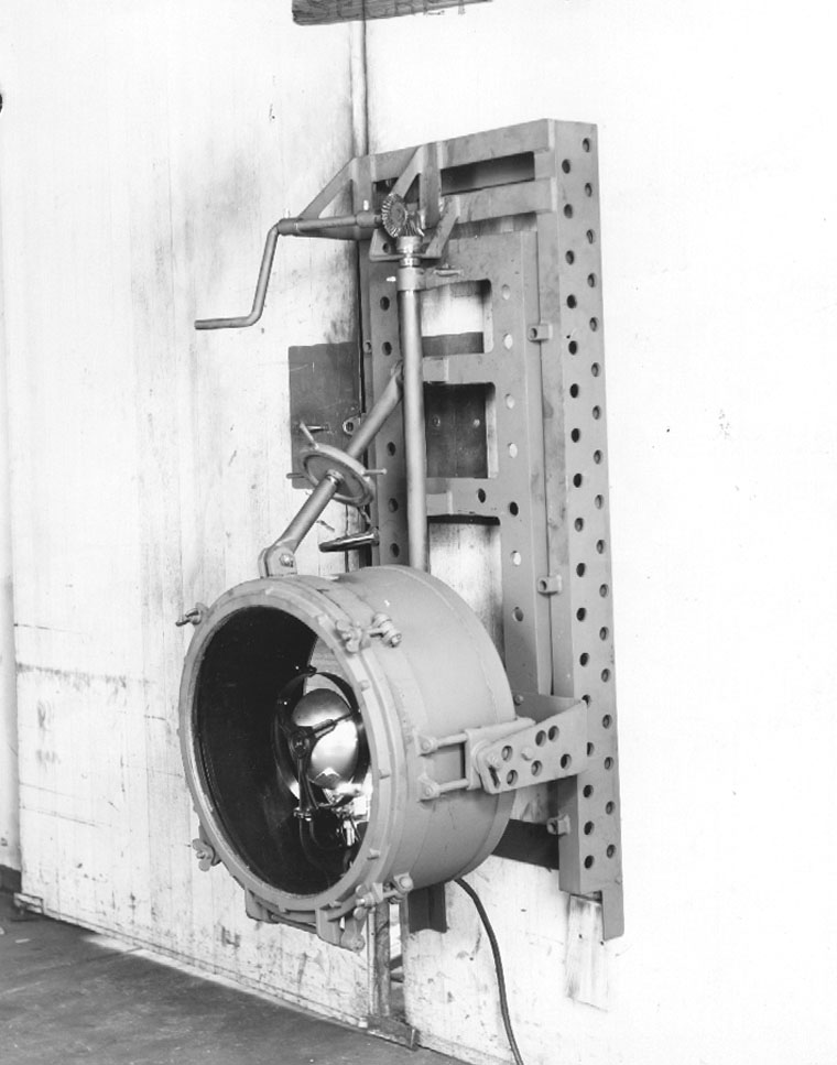
The searchlight projects were set up at the request of the Director of Technical Services on 17 July and 14 December 1942, respectively, to cover the development of a suitable searchlight for target identification by aircraft engaged in antisubmarine warfare. During the period that this project was active, five separate types of searchlights were tested before a satisfactory solution to the problem was arrived at. In testing the searchlight, flights were accomplished on each installation under varying night weather conditions, using boats and buoys as targets. |
||
| During July, 1942, a 36 inch 25,000,000 candlepower Sperry carbon arc lamp was tested. This lamp was mounted in the right rear corner of a B-17 bomb bay; current was supplied by 2600 pounds of batteries. This light was found to be unsatisfactory due to the great amount of | ||
119. |
||
light reflected back into the observer's eyes from slight haze, which made it impossible to see the surface of the water. An additional disadvantage was the fact that the batteries were of excessive weight and required recharging after four minutes of use. It was also necessary to replace the carbon electrode after each thirty seconds of use. |
||
A 24-inch General Electric searchlight with parabolic reflector was tested during August, 1942. This light operated from the airplane's electrical system and used a 3000 watt 26-V lamp of the type normally used as a landing field flood light. Results of testing were very similar to the 36-inch Sperry carbon arc light. The observers could not see the water because of large amounts of light reflected back into their eyes. |
||
A third searchlight tested by this Group was the 18-inch Sperry light which used a 900 watt incandescent lamp using 33 volts across the terminals and drawing about 30 amperes. The light which weighed about 40 pounds, was installed in the rear hatch of a B-24 at an angle of 11 degrees of horizontal flight. Results of tests showed that enough light was furnished to permit identification of a target and enable a bombardier to sight the target at night. However, this light was not considered to be a satisfactory solution, since it worked well only under favorable weather conditions. Slant ranges of 1900 feet in clear weather and 1200 feet in hazy weather at an altitude of 300 feet were obtained. At 300 feet |
||
120. |
||
the beam was from 75 feet to 100 feet wide and 400 feet to 500 feet long. A limited number of these lights mounted on swivel mounts were secured by Wright Field for the Antisubmarine Command with the understanding that this type of light was merely a "stop gap" and served as the most immediate solution of the identification problem. Work was continued on this project at Langley Field. |
||
In the meantime a searchlight was being constructed by General Electric which used a 3000 watt 28-V bulb. The assembly for this light had vertical control, but it did not have movement in the azimuth position. Testing of this light was begun in March, 1943, with favorable results. Targets were picked up at 500 feet range from altitudes of 500 to 600 feet. This light had a beam spread 2-1/2 degrees high and 7 degrees wide. It was believed that the G.E. light source was superior to any light tested thus far, and would serve well under varying weather conditions. |
||
The next step was the development of a retractable mounting for the searchlight drum so that it could be drawn up into the bomb bay of the rear B-24 bomb bay on the left side. In cooperation with Wright Field several mounts were fabricated which had both electrical and manual movement for the light beam. As a result of testing several models, recommendations and specifications were drawn up, and the American Gas Accumulator Company constructed several production models. |
||
121. |
||
The AGA searchlight is designed to be carried inside the bomb bay except when it is actually in use. It is provided with an electrically operated hoist for extending and retracting the searchlight drum. The General Electric 3000 watt 28-V bulb is used. Provision is made for normally controlling the direction of the beam from 20 degrees right to 20 degrees left of the line of flight and from 10 degrees to 45 degrees below the horizontal line of flight. The searchlight is remotely controlled from the bombardier's compartment, and indicators are provided to show the direction of the beam. |
||
Results of testing show that the target could be picked up at one-half mile from altitudes of 300 to 500 feet and vessels could be identified within one-quarter of a mile on either side of the beam. |
||
Except for limited service tests of the AGA light, no further activity took place at this headquarters. |
||
Test Data |
||
Tests: |
||
No. of flights - 16 Total flight time - 34:25 |
||
Installation of equipment: |
||
| No. military man hours - 150:00 No. plane hours - 105:00 | ||
Instructions: None |
||
Total hours planes used on project: 137:35 |
||
Total man hours expended in installations and instructions: 150:00 |
||
122. |
||
SS #15 - IMPROVEMENTS IN LOW ALTITUDE BOMB TRAJECTORY |
||
This is a general information file regarding various means of modifying bomb trajectories to increase accuracy at low altitudes. Limited tests to investigate the effect of attaching parachutes six feet in diameter to Mark 17 depth charges were accomplished with unsatisfactory results, because additional error was introduced due to fouling of parachute lines and effects of cross winds on the large area of the parachutes. M-40 cluster bombs were also tested with similar unsatisfactory results. |
||
Test Data |
||
Tests: |
||
No. of flights - 2 Total flight time - 8:30 |
||
Total hours planes used on project: 8:30 |
||
SS #16 - SLICK DROPPING DEVICE |
||
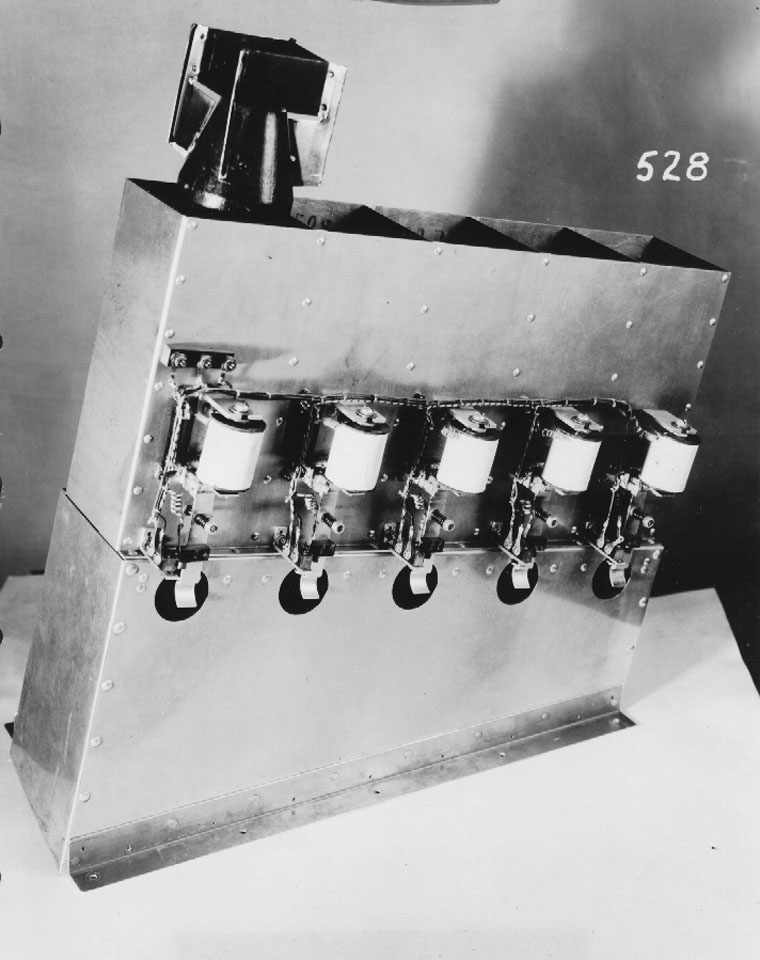
The automatic slick dropper was devised as a means of instantly marking the position of a submerged submarine as revealed by Mark IV or VI MAD contacts. It may also be used by the navigator to check wind drift when flying over water. |
||
123. |
||
The design and development of this unit was carried out by Columbia Laboratory personnel at Langley Field in July, 1942. A pilot model made entirely in the Columbia Laboratory was installed in a B-18 and after very thorough testing proved to be highly satisfactory. |
||
The slick dropper consists of five chambers which accommodate regular torpedo type drift markers. Trapdoors, placed on the lower end of these chambers are released by a coil and armature device. Sequence relays are provided so that slicks are released one at a time and in controlled sequence. Reloading is accomplished by resetting the trapdoors and refilling the chambers with the materiel to be dropped. In addition to the push button release installed at the ASV-MAD operator's position, releases are also provided for the pilot and bombardier so that slicks may be dropped from any one of the three positions, if desired. |
||
The slicks are dropped on MAD contact with the target. Since this contact is made directly over the target, the trajectory of the slicks will carry them beyond the actual position of the target. However, if a constant altitude is maintained and a series of slicks is dropped, with alternate headings on the target, this over-shooting does not cause any apparent difficulty in determining the course and position of the submerged submarine. |
||
The slick dropper has proven to be a valuable aid in flying trapping circles or clover leaf patterns* and has also been used extensively |
||
- - - - - - - - - - - - - - - - - - - - - - - - - - - - - - - - - - - - - - - - - - - - - - - - - - - - - - - - - - - - |
||
* See illustrations following page 53. |
||
124. |
||
to mark the position of sonic radio buoys during tests and tactical operations. |
||
Test Data |
||
Tests: |
||
No. of flights - 4 Total flight time - 6:10 |
||
No. of ground tests - 7 Total ground time - 43:30 |
||
Installation of equipment: |
||
No. civilian man hours - 76:30 No. plane hours - 43:30 |
||
| No. military man hours - 27:00 | ||
Instructions: None |
||
Total hours planes used on project: 93:10 |
||
Total man hours expended in installations and instructions: 103:30 |
||
SS #17 - ALTIMETER, HIGH ALTITUDE RADAR |
||
| At the request of the Director of Technical Services, 1st Sea Search Attack Group in cooperation with National Advisory Committee for Aeronautics conducted tests in a flight investigation of high altitude radar altimeters. The tests were intended primarily to determine the accuracy of the SCR-518, or 1 to 20,000 foot altimeter, at very low altitudes and to reveal any possible effects on the altimeter accuracy of the terrain over which the airplane was flying. | ||
125. |
||
To determine the height of the airplane above the ground, a motion picture camera fitted with a bubble level, was mounted in the airplane in such a way that its optical axis could be adjusted vertically in steady level flight at a suitable indicated airspeed. The airplane was then flown at that speed across a row of targets of known size or spacing located on the surface of the ground or water. The height of the airplane above the surface was calculated from the size or spacing of the target images on the film. |
||
The results of the tests indicated that below 500 feet a given reading of the altimeter may be in error by as much as 40 feet. Errors of this magnitude were apparently a consequence of the low reading accuracy and difficulty of adjustment of the instrument. A change in terrain from level ground without trees to shallow, calm water had no detectable effect on the altimeter accuracy. |
||
Test Data |
||
Tests: |
||
No. of flights - 10 Total flight time - 15:20 |
||
Installation of equipment: |
||
No. civilian man hours - 5:00 No. plane hours - 5:00 |
||
| No. military man hours - 27:00 | ||
Instructions: |
||
| No. civilian man hours - 8:00 | ||
Total hours planes used on project: 20:20 |
||
Total man hours expended in installations and instructions: 13:00 |
||
126. |
||
SS #18 - MARKER FLOAT |
||
Testing on this project was begun on 10 July 1942. |
||
Various types of night marker devices were tested under this designation, which included the Columbia Laboratory's Night Marker, Mar V Floatlights, and a long burning Navy type floatlight. |
||
The Columbia Laboratory marker was developed at 1st Sea Search Attack Group by personnel from Columbia. It is an electric float marker made of .020 inch galvanized iron and is similar in shape to the Mark 25 flare except that the length is only 12-7/8 inches. Two Burgress #2 (or Everready #950) batteries provide current for the 2-1/2 volt screw base bulb. The float burns for five hours and is visible at night for a distance of four miles at 300 feet altitude. The float tested satisfactorily, however it was superseded by the Mark V floatlight equipped with rocket motor for retro firing. |
||
Development of the Mark V floatlight was carried out by California Institute of Technology. Details of testing these lights will be found under project SS #40. |
||
A Navy type long burning floatlight was also tested by this Group. The burning time for this light is 45 minutes, and it can be seen up to nine miles at 300 feet. It was believed that this type of light would be satisfactory for night use; however, it was recommended that |
||
127. |
||
the containers be modified so that the lights may be dropped by the automatic slick dropper. |
||
Test Data |
||
Tests: |
||
No. of flights - 6 |
||
Total Plane Hours: 12:10 |
||
SS #19 - MARK 13 MINE |
||
Loading and vibration tests on the Mark 13 Mine were carried out at this Group. It was determined that up to six Mark 13 Mines could be loaded in the bomb bays of either a B-17 or and LB-30. |
||
Long range flights to test the effect of flight vibrations on the M-4 mechanism for the Mark 13 Mine were satisfactorily completes at this Group by Naval Ordnance personnel. |
||
Test Data |
||
Tests: |
||
No. of flights - 4 Total flight time - 11:30 |
||
Installation of equipment: |
||
| No. civilian man hours - 34:00 No. military man hours - 84:00 | ||
Total hours planes used on project: 11:30 |
||
Total man hours expended in installations and instructions: 118:00 |
||
128. |
||
SS #20 - RADAR BOMBSIGHT (L.A.B.) |
||
The original proposal for a Radar Bombsight was submitted by Lt. Ned. B. Estes, Jr., on 10 May 1942, and was developed by the Radiation Laboratory of MIT. This proposed sight consisted of an indicator tube (Mark 10) of suitable size and scale representation mounted on a bomb sight control unit with a fixed vertical azimuth reference line at the zero point of the drift scale. Such an arrangement would stabilize the tube, and displacement of the ship in azimuth would be represented by the displacement of the reference line from the image of the target on the tube. Arranged in this manner the bombardier would be able to correct the airplane's flight for drift by setting the tube so that the target appears to be bisected by the reference line and by use of control knobs, in a conventional manner, stop all apparent motion of the target from that line. |
||
The cable that normally drives the telescope of an "M" series sight would be arranged to drive a lateral reference line on the front of the tube; and, by synchronizing the speed of travel of the lateral reference line with the image on the target, the ground speed would be measured and an automatic release made. |
||
This proposed sight would be operated in a conventional manner except for the fact that the bombardier would see and perform his operations on the target through a medium of radio waves instead of light waves. However, no arrangement was suggested for the introduction of cross trail |
||
129. |
||
into the computations. |
||
Within a short time MIT produced a bread board model of this sight which was tested during the latter part of July, 1942, with promising results. However, modifications were suggested by the 1st Sea Search Attack Group which included a redesigned indicator scope on which the target would appear small enough so that the bombardier would be better able to perceive the drift. In the original model the target almost filled the indicator scope. |
||
While it was anticipated that testing and developing of the Radar Bombsight would be continued by the 1st Sea Search Attack Group, this was not actually the case, as field tests of the preproduction model were conducted at Eglin Field, through the crew and plane for these tests were supplied by this Group. |
||
Consequently, there was no further activity in connection with this project at this station until March, 1943, when L.A.B. equipment was installed in B-24D #123708. After necessary flight tests to check the calibration of ground speed and dropping distance, regular flights were scheduled to train additional bombardiers in the use of this equipment. |
||
B-24D #123878 with L.A.B. RD-217-T-1 Model No. 1 installed, was brought to Langley Field 14 April 1943, after proof tests had been completed at Boca Raton. This plane and equipment has since been used in an extensive training program in connection with the Wright and Scott projects. |
||
130. |
||
On 5 June 1943, tests were initiated to determine the accuracy of a modified MIT L.A.B. set at higher altitudes. This equipment had the maximum slant range increased from 5,000 to 15,000 feet, and tests were run at altitudes up to 10,000 feet to determine operation from these heights. Preliminary tests indicated that this equipment functioned properly, but further adjustments as well as additional training of bombardiers was necessary before the true accuracy of this modified L.A.B. could be determined. |
||
Additional replacement crews were trained in L.A.B. tactics and technique by the 1st Sea Search Attack Group and, after the inactivation of that Group, by the 11th AAF Base Unit.* |
||
Test Data |
||
Tests: |
||
No. of flights - 90 Total flight time - 228:12 |
||
No. of ground tests - 2 Total ground time - 31:00 |
||
Installation of equipment: |
||
No. civilian man hours - 384:00 No. plane hours - 208:00 |
||
Total hours planes used on project: 259:12 |
||
Total man hours expended in installations and instructions: 398:00 |
||
Instructions: |
||
No. civilian man hours - 14:00 |
||
- - - - - - - - - - - - - - - - - - - - - - - - - - - - - - - - - - - - - - - - - - - - - - - - - - - - - - - - - - - - |
||
| * A detailed account of LAB training will be undertaken in Chapter IV. | ||
131. |
||
SS #21 - MARK 24 MINE |
||
This device was assigned a project number on 22 July 1942, however no testing other than conducting loading tests on an inert model was accomplished. |
||
SS #22 - ECHO BOXES |
||
Testing on this project started on 17 July 1942. The echo box is a device used to check the over-all efficiency of Radar equipment during flight or on the ground. |
||
The echo box consists of a resonant cavity in the form of a cylindrical can, with a tuning plunger, which is permanently mounted in the plane. This can is about six inches in diameter and five inches high. A flexible transmission line runs from the resonant box to a small dipole permanently mounted on the plexiglass nose. If the elevation of the ASV Spinner is raised to maximum (a position not normally used in flying), the small dipole will take energy from the system, store it in the resonant cavity, and continue to emit energy after the passage of the transmitted pulse for a period of about 20 microseconds. The emitted energy from the echo box will appear on the indicator of the ASV system in the form of a line, the length will be indicative of the performance of the radar equipment. |
||
132. |
||
Testing of a Radiation Laboratory echo box and the Western Electric "wobble type" echo box has been accomplished at Langley Field. Both units have been found satisfactory and are highly useful pieces of radar test equipment. This Group recommended that the "wobble type" box should be installed as a part of each "S band" radar system for indicating the condition of SCR-717 equipment, since this type of box requires no meter and can be manufactured easily and in quantities such that one can be installed in each airplane. It was also recommended that the Radiation Laboratory box be supplied in portable form from radar test equipment. |
||
Test Data |
||
Tests: |
||
No. of flights - 3 Total flight time - 4:40 |
||
No. of ground tests - 100 Total ground time - 200:00 |
||
Installation of equipment: |
||
No. military man hours - 40:00 |
||
Instructions: |
||
| No. military man hours - 20:00 | ||
Total hours planes used on project: 204:40 |
||
Total man hours expended in installations and instructions: 40:00 |
||
SS #23 - INVESTIGATION OF TARGET |
||
No active testing took place at this station under this category. The file was set up as a general information file relating to various |
||
133. |
||
means of target identification. Officers of this organization attended a demonstration on 19 September 1942, at N.O.B. in Norfolk pertaining to various uses of infra-red and ultra-violet apparatus. A representative from Sea Search also attended a Naval demonstration off Solomon's Island on August 30, 1942, employing infra-red and ultra-violet light for a beach landing. Application of these invisible lights in connection with Sea Search activities has been very limited. Results of some testing employing an ultra-violet light source is reported under SS #25. |
||
SS #24 - SONO BUOY |
||
Beginning in July, 1942, numerous tests have been conducted on the radio sonic buoy which was developed by the Columbia Division of War Research at Naval Underwater Sound Laboratory. |
||
The sonic buoy consists of a tubular float arranged with a hydrophone which hangs 20 feet below the water surface and converts water sounds to electric voltages. These voltages are amplified and applied to a low power frequency modulated transmitter with the float. The job of the sonic buoy is to pick up sounds made by a submarine and transmit then in form of radio waves which can be received in aircraft and used as another agent to help identify and verify the source of MAD signals. Tests made by the 1st Sea Search Attack Group show that the maximum useful radio radio range is 17.5 miles at an airplane altitude of 500 feet. |
||
134. |
||
Testing and development work at Langley Field on the sono buoys included dropping tests, experimentation on the most suitable antenna to be used, and determining the proper location of the sono buoy receiver in both B-18 and B-24 aircraft. In addition, tests were successfully completed to incorporate an airplane's interphone system with the sonic buoy receiver so that all members of the crew could listen to the sonic sounds at one time. |
||
Sono buoys have been field tested by this Group on trips to Trinidad and Key West and have been found to be a valuable accessory in flying MAD tactics. Tactics employing four buoys each using a different frequency to gain directivity have been used with a fair amount of success. During the period of July, 1942 through July, 1943, the 1st Sea Search Attack Group had eight B-18's and two B-24's equipped with sonic buoy receivers. During this same period 108 Sono buoy transmitters were expended. Most of these were launched to carry out the testing program and the remainder were expended mainly at the Key West maneuvers during May, 1943. |
||
A final report on this device was submitted by this headquarters to the Director of Technical Services on 16 January 1943, in which it was recommended that tests be conducted with available buoys with the principal objectives as follows: |
||
1. To develop improved tactical use in conjunction with improved MAD Mark IV, ASV, vertical bombs, etc. |
||
135. |
||
2. To improve the operation of the buoy itself, with particular regard to: |
||
a. Improvement of the hydrophone signal-to-noise ratio. |
||
b. Providing directional capabilities. |
||
c. Reducing size of present radio sonic buoy. |
||
It was further recommended that the following suggestions be adopted: |
||
1. That the sonic buoy have shockproof mounting for its transmitter section. |
||
2. That the buoys be packed in four compartment containers, each of the four buoys having a different frequency. The container must be arranged to facilitate easy removal of the buoys in the airplane. |
||
3. That there be developed a simple apparatus to provide a test signal for the hydrophone, which signal may then be picked up and measured in approximate terms of frequency deviation by the receiver. |
||
Most recent developments and tests have been concerned with a direction indicating sonic buoy. Members of this Group have made constructive suggestions in regard to the best means of obtaining directional indications. However development of an actual directivity model of the sono buoy is taking place at the Naval Underwater Sound Laboratory, developers of the original sono buoy. |
||
136. |
||
Test Data |
||
Tests: |
||
No. of flights - 17 Total flight time - 37:50 |
||
No. of ground tests - 11 Total ground time - 43:40 |
||
Installation of equipment: |
||
| No. civilian man hours - 57:00 | ||
No. military man hours - 73:00 No. plane hours - 37:00 |
||
Total hours planes used on project: 118:30 |
||
Total man hours expended in installations and instructions: 130:00 |
||
Sono Buoys Expended: |
||
Received 210 |
||
Less Inventory (Aug. 1, 1943) 92 |
||
Expended (Includes Testing |
||
Training and Tactical Use) 108 |
||
SS #25 - RECOGNITION OF VESSELS BY ULTRA-VIOLET REFLECTION |
||
| Tests were conducted by this Group and NDRC personnel in September and October, 1942, in order to provide a recognition system entirely under control of the aircraft pilot and invisible to enemy surface craft. An ultra-violet autocollimator was installed on a crash boat and an ultraviolet light source was mounted in a B-18. Results showed that a satisfactory identification signal could be obtained for a plane flying at 300 feet altitude. The average range at which the light was visible was 3700 feet. No further testing was accomplished, and the results were turned over to the Navy for consideration. | ||
137. |
||
Test Data |
||
Tests: |
||
No. of flights - 3 Total flight time - 3:55 |
||
Installation of equipment: |
||
No. civilian man hours - 4:00 |
||
Total hours planes used on project: 3:55 |
||
Total man hours expended in installations and instructions: 4:00 |
||
SS #26 - 100-MILE B SCOPE (517C) |
||
This project was set up to take care of testing of 517C equipment; however, it was later declined to submit all reports on ASV equipment under SS #10, and project SS #26 was transferred to SS #10. |
||
SS #27 - RADR BEACON |
||
The Radar Beacon was developed by the Radiation Laboratory and installed at Langley Field where initial tests were started 24 August 1942, as authorized by the Director of Technical Services. |
||
| The Radar Beacon is a device which receives a radar signal from an airplane equipped with SCR-517C or similar type of micro-wave radar and automatically send back a return signal. The radar observer in the | ||
138. |
||
plane can see this beacon on his indicator screen and is able to identify the particular beacon station by its code. The position of the code pattern on the indicator screen shows the radar observer the direction and distance in miles to the beacon station. |
||
The radar observer in the airplane can operate the beacon station on the ground at any time merely by throwing a switch from "RADAR" to "BEACON". This switch causes a longer signal (2.5 microsecond, rather that 1 microsecond) then normal to be transmitted by the airplane. This long signal is received by the beacon receiver which passes it on to the discriminator. The discriminator rejects the ordinary radar signals but passes the longer signals to trigger the coder. The coder then operates the beacon transmitter sending back to the airplane the preset coded signals. A number of airplanes can operate one beacon station without interference. |
||
The code now set up at Langley consists of three one micro-second signals spaced 15 micro-seconds apart. These appear on the indicator screen as three horizontal lines one above the other. The code can be changed by changing the time interval between any two of these three signals. This will change the vertical distance between the lines on the screen. The distance to the beacon is read on the vertical scale in miles from the bottom of the beacon signal. Direction is read on the horizontal scale in degrees right or left using the center of the beacon signal. |
||
139. |
||
The radar sets used with the beacon have a one-hundred mile maximum range. In addition to this, an important limitation in the range of the beacon is the curvature of the earth. From a beacon station mounted 100 feet in the air, the "line of sight" distance to an altitude of 300 feet is 35 miles; to an altitude of 1000 feet, 50 miles; to an altitude of 4000 feet, 100 miles. Due to refraction, ranges beyond the expected distance for a given altitude are often obtained, but the amount of refraction depends on weather conditions and is unreliable. |
||
The beacon requires little maintenance, even though it must be turned on twenty-four hours a day. Operation is entirely automatic so that it does not require an operator. It does require inspection and testing at intervals to insure proper operation. At Langley the beacon is inspected daily, but a much less frequent inspection will probably be found satisfactory on production equipment. The beacon here is triggered a large part of the time due to its proximity to three different radar sections' testing equipment and therefore takes more than normal punishment. |
||
Many modifications were made and tested until the beacon was finally determined to have sufficient range and reliability to warrant freezing the design. The findings were then turned over to the Galvin Company of Chicago, and production of these units was started. |
||
140. |
||
During the tooling up period a few changes were made on the electric circuits, and it was thought best to try the changes in the field before Galvin started turning out the units. Consequently a further series of tests were run at Langley Field using a Philco and Lipkin receiver in conjunction with the original Beacon installations. It was finally determined that a simple video receiver gave the most reliable results, as consistent ranges of 100 miles at 5000 feet were obtained by all suitably equipped planes. |
||
The first Galvin production model was received at Langley Field on March 1st and on all tests to date has proven to be satisfactory in regards to maximum range desired and general reliability. |
||
The Radar Beacon as a homing device has proven its reliability and is a very valuable aid to navigation in obtaining landfalls or when flying under instrument conditions. |
||
Many variations of combinations of receivers and transmitters were extensively tested before the present production model was frozen and during this period field tests were also conducted on the Low Power Portable Beacon (SS #62) by the 1st Sea Search Attack Group. These beacons were found to have reliable ranges between 40 and 50 miles and are proving their usefulness in many theatres of operation. |
||
141. |
||
Test Data |
||
Tests: |
||
No. of flights - 143 Total flight time - 297:00 |
||
No. of ground tests - 16 Total ground time - 13:30 |
||
Installation of equipment: |
||
No. civilian man hours - 18:00 |
||
| No .military man hours - 10:00 | ||
Instructions: |
||
| Total civilian man hours - 21:00 | ||
Total hours planes used on project: 330:00 |
||
Total man hours expended in installations and instructions: 49:00 |
||
SS #28 - CAMOUFLAGE |
||
Tests were conducted at Langley Field during the period January 8th through 21st, 1943. Five B-18's received various color arrangements of camouflage as follows: |
||
B-18 #37-464: Underneath surfaces: Insignia white camouflage enamel, shade #46. Side and top surfaces: flight camouflage enamel white over black camouflage to produce a bluish "haze" effect. |
||
B-18 #37-465: All exterior surfaces: Flight camouflage enamel, white applied in a pattern of graduated light reflectance values over black camouflage enamel, to produce a bluish "haze" effect. |
||
| B-18 #37-621: Underneath surfaces: White insignia camouflage enamel. Vertical control surfaces and side of fuselage: Neutral gray camouflage lacquer. Top surfaces: Left in original color of dark olive drab. | ||
142. |
||
B-18 #37-561: Underneath surfaces: Neutral gray. Side and top surfaces: Dark olive drab. |
||
B-18 #37-574: Left in original finish consisting of insignia white on all surfaces. |
||
All flights were conducted between 9:00 and 16:00 o'clock on days of unlimited ceilings and no abnormal haze conditions existed. The planes flew in formation at altitudes of 2,000, 4,000, 6,000, and 10,000 feet from various directions. Observations were made from the ground and also from a sixth plane. |
||
The camouflage color arrangement found in the tests to have the highest over-all effectiveness in all attitudes of the airplane with relation to observers, sun, and background conditions, was as follows: |
||
1. Underneath surfaces, leading edges, and "front view" areas: Insignia white, shade #47. |
||
2. Side (essentially vertical) surfaces: natural gray shade No. 43. |
||
3. Top surfaces: Dark olive drab shade No. 41. |
||
Test Data |
||
Tests: |
||
No. of flights - 5 Total flight time - 23:05 |
||
SS #29 - ONE-MAN PARACHUTE BOAT |
||
No testing was accomplished at this headquarters in regard to this equipment. |
||
143. |
||
SS #30 - LIGHT MICROPHONE BUOY |
||
This project was originated on 23 October 1942, to cover the development of a microphone buoy with an electric bulb attachment. The idea consisted of a microphone which would pick up underwater sounds and in turn operate a relay which would illuminate a light signal. This project was dropped on 20 November 1942, in view of the difficulty in making a buoy which would distinguish between wanted and unwanted sounds. |
||
SS #31 - USE OF WALKIE-TALKIE ON AIRCRAFT |
||
Testing of the Navy TBY-1 and Army SCR-194 Walkie-Talkies took place ay Langley Field during August, 1942, to determine the practicability of using either of these types for communication between patrol planes and unconvoyed merchant vessels. |
||
TBY-1 |
||
A test flight with the Navy TBY-1 radio set was made in a B-17. The vertical whip type antenna, part of the radio compass set, was used as the radiator. This antenna is extended beneath the ship directly behind the loop antenna, and the ship mass acted as an excellent reflector. |
||
The resultant pattern was very effective for a 20 to 25 mile circular coverage at 8000 feet. Attenuation beyond this range was very sharp, and readability decreased to zero. |
||
The vertical antennas as used on the type B-17 for the compass receiver possessed all necessary characteristics for adaptation to this equipment. However, due to the resonant sharpness of this type antenna, |
||
144. |
||
it may be desirable to make provisions for mechanical changing of antenna length to accommodate the wide band of frequencies this equipment is capable of operating on. The vertical Marconi antenna was found unsuitable for use in this case because of the mechanical and electrical difficulties of coping without a prohibitive loss of power. |
||
SCR-194 |
||
Several tests were made with the SCR-194 in flight. On one test the dipole antenna post of the marker beacon equipment was used as a radiator. Contact was satisfactory on the ground but was lost on takeoff. Due to the fixed antenna coupling, this set was not successful for air-ground communication in its present state. |
||
A special antenna was made, and the set was tried again using a small liaison ship. Again after take-off contact was lost due to the extreme change in coupling between the antenna and the ground. The special antenna was made of rigid aluminum tubing cut to resonate at 50 to 60 megacycles. |
||
On the basis of these tests, it was concluded that: |
||
1. The Navy TBY-1 set could be utilized with reasonable assurance that it will function satisfactorily within a radius of 25 miles. |
||
2. The Army SCR-194 is not satisfactory without modification. By altering the antenna coupling and making certain circuit changes, |
||
145. |
||
this set could probably made to operate within a limited range, but it would not apparently be as good as the Navy set. |
||
3. Since neither of these sets utilize the power supply of the aircraft, it would appear that the better course of procedure would be to push further development of the Army SCR-264 or some similar set especially designed for aircraft use. |
||
Test Data |
||
Tests: |
||
No. of flights - 3 Total flight time - 7:05 |
||
No. of ground tests - 2 Total ground time - 7:00 |
||
Installation of equipment: |
||
| No. military man hours - 1:00 | ||
Total hours planes used on project: 14:05 |
||
Total man hours expended in installations and instructions: 1:00 |
||
SS #32 - MAGNETIC AIRBORNE BOMBSIGHT |
||
| Testing of the magnetic airborne bombsight began in November, 1942. This device comprises essentially two complete Mark VI MAD units and a flare and bomb release mechanism. A MAD magnetometer head and servo system are mounted in "birds" on the two wing tips of the airplane. In flying near a submerged target, the MAD equipment having its | ||
146. |
||
magnetometer closest to the target receives the largest signal. The sum and difference of these signals are used to operate a retro bomb and retro flare release mechanism. A retro flare is released if the airplane flies to one side of the target, and both the bomb and flare are released if the airplane flies over the target. |
||
Two types, the "O" and "T" MABS, were tested by this Group. The O-type is generally used with a single Mark VI MAD installation and consists of a tripping device that operates on the crest of a magnetic signal. The T-type unit is much more elaborate and operates in conjunction with two Mark IV MAD units which give it a directional sense. It will not fire retro bombs unless the airplane is in the approximately correct position with respect to a submerged submarine to score a hit. The unit will cause retro flares to be fired if a run is made too far offside of the target for effective retro bombing. |
||
T-type MABS also contains a right-left indicator and retro bomb and retro flare indicating lamps that show various members of the airplane crew in different parts of the airplane, what is happening during an action. |
||
One experimental T-type MABS installation was made in B-18 #9021, and two such installations were made in B-24D #684. These installations were rigorously tested in 112 hours of flight, and a large amount of developmental work was done on the units in the |
||
147. |
||
laboratory by Sea Search personnel under the direction of A.I.L. engineers which contributed measurably to the final successful design of the T-type MABS. |
||
A means of accurately recording the release point of MABS fired retro bombs and retro flares by camera was devised by A.I.L., O.R.G., and Army personnel for the Plum Tree Island magnetic target range. This system comprised the placing of vertical poles at 50 and 100 feet intervals along lines bearing through the magnetic target and the four cardinal points of the compass. The intersection point of projection lines extending through the length axis of two or more poles on the photographs indicate the point of release. This system was used to determine retro bomb release points during the tests made on T and O-type MABS over the Plumb Tree Island magnetic submarine simulator coil. |
||
Eighty-eight officers received training on directional MAD, MABS, and MAD retro bomb tactics. This training was conducted by Sea Search Army officers. |
||
Tactics employing the use of MABS, MAD, and retro bombs and flares have been worked out by members of this organization.* During the exercises at Key West it was found that the tactics were very satisfactory, and results appear in report of 7 June 1943, entitled "Key West Exercises". |
||
- - - - - - - - - - - - - - - - - - - - - - - - - - - - - - - - - - - - - - - - - - - - - - - - - - - - - - - - - - - - |
||
* Operating Instructions for MABS are contained in Appendix 33. |
||
148. |
||
Test Data |
||
Tests: |
||
No. of flights - 63 Total flight time - 112:00 |
||
No. of ground tests - 34 Total ground time - 100:00 |
||
Installation of equipment: |
||
| No. civilian man hours - 69:00 No. plane hours - 76:00 | ||
| No. military man hours - 114:00 | ||
| Instructions: None | ||
Total hours planes used on project: 288:00 |
||
Total man hours expended in installations and instructions: 183:00 |
||
SS #33 - MIT AUDIO-INDICATOR |
||
The 1st Sea Search Attack Group conducted tests on this device during March, 1943, with the cooperation of MIT personnel. |
||
The audio indicator was designed to operate with ASV radar equipment. It produces an audio note in a pair of headphones when the radar equipment picks up an echo from some object such as a ship. As a result the radar operator need not keep such a careful watch on the scope, since he will receive an audio warning when a signal has been picked up. |
||
The audio indicator changes video signals into audio signals. It must distinguish between noise and signal and gate out the main bang and near sea return signals. The gate has two controls; one control |
||
149. |
||
gates out the main bang and all signals within two to ten miles and is labeled "Delay". The second control governs the width of the gate so that the wider the gate the greater is the range, but also more noise is received. |
||
The audio indicator performed satisfactorily on a B-18. Audio notes were heard when ship signals appeared on the scope of 517C Radar. Preliminary tests with the audio indicator is in connection with 717A equipment on a B-24 were undertaken at Langley Field. Results were not satisfactory due to the maladjustment of certain parts, and the unit was returned to MIT for further modification. However, it is believed that the audio indicator tests with 717A equipment will eventually be satisfactorily completed. |
||
Test Data |
||
Tests: |
||
No. of flights - 4 Total flight time - 7:15 |
||
No. of ground tests - 2 Total ground time - 8:00 |
||
Installation of equipment: |
||
| No. civilian man hours - 14:00 No. plane hours - 14:00 | ||
| Instructions: None | ||
150. |
||
Total hours planes used on project: 29:15 |
||
Total man hours expended in installations and instructions: 14:00 |
||
SS #34 - MARK VI MAD |
||
The desirability of directional indications having been demonstrated by thorough testing of the MARK IV-B2 equipment, a very compact and light weight unit was developed especially designed for dual installations. On 17 October 1942, it was directed that the five B-18's being equipped with retro rails should also have directional MAD Mark VI installed. |
||
This Mark VI MAD equipment operated in practically the same manner as does the Mark IV-B-2. Its weight, however, is approximately one-half that of the earlier equipment. Its sensitivity and reliability are comparable. Since the weight of two complete Mark VI MAD units is not objectionable (265 pounds) a dual installation is used to indicate direction. In this case the detector elements are mounted on the wing tips of the airplane. When the airplane passes over a submerged target, the detector element closest to the target will encounter the greatest change in the earth's field and indicate a larger signal. It is then possible to tell whether the airplane has passed to the right or the left of the target. |
||
151. |
||
Reductions in the operating time consists in the Mark VI MAD equipment renders it a satisfactory means either as a single or double unit for bombing, providing retro bombs are employed. Auxiliary equipment MABS (SS#32) was designed for this purpose. |
||
Four Mark VI dual MAD installations were made in B-18 airplanes at Langley Field with the assistance of A.I.L. personnel from Wright Field. These installations were augmented with double recorder attachment by the Sea Search and A.I.L. personnel as a means of securing directivity indications. |
||
Since there exists only minor differences between the Mark IV-B2 and Mark VI equipments, mechanics and operators trained in the maintenance and operation of Mark IV-B2 equipment quickly became skilled in the care and operation of the newer equipment.* |
||
In general, Mark VI MAD equipment was found to be as reliable as Mark IV MAD equipment, as easy to service, and as capable of equivalent results in respect to noise level and range. Its directional characteristics were an added advantage that made its tactical employment more useful and effective than the older MAD IV-B2. |
||
Test Data |
||
Tests: |
||
No. of flights - 161 Total flight time - 264:00 |
||
No. of ground tests - 27 Total ground time - 79:00 |
||
Installation of equipment: |
||
| No. civilian man hours - 2,742:00 | ||
| No. military man hours - 484:00 No. plane hours - 1,041:00 | ||
| Instructions: None | ||
Total hours planes used on project: 288:00 |
||
Total man hours expended in installations and instructions: 183:00 |
||
- - - - - - - - - - - - - - - - - - - - - - - - - - - - - - - - - - - - - - - - - - - - - - - - - - - - - - - - - - - - |
||
| * See Appendix 26 for tactical procedure for B-18 airplanes equipped with Mark VI MAD. | ||
152. |
||
| Instructions: None | ||
Total hours planes used on project: 1,384:00 |
||
Total man hours expended in installations and instructions: 3,226:00 |
||
SS #35 - STADIA TYPE RANGE FINDER |
||
This project was set up on 17 September 1942, to cover testing of a small range finder developed by Dr. O'Brien of Rochester University. It was believed the device might have some utility in connection with formation MAD flying. No actual testing took place at Langley Field, and the project was closed out on November 20, 1942. |
||
SS #36 - COLUMBIA LABORATORY MARKER BUOY |
||
Tests on the marker buoy were started on September 9, 1942. This unit comprises a 55-pound buoy having an anchor and an electric light. The buoy was to be dropped at a location where a MAD signal had been received and was to assist planes and surface craft in finding the location. |
||
Preliminary testing indicated that this device was not practicable, and the project was dropped January 9, 1943. |
||
Test Data |
||
Tests: |
||
No. of flights - 4 Total flight time - 5:35 |
||
No. of ground tests - 4 Total ground time - 10:00 |
||
Total hours planes used on project: 15:35 |
||
153. |
||
SS #37 - ODOGRAPH |
||
Installation of the first Odograph in B-18 #7561, assigned to the 1st Sea Search Attack Group, was completed 17 September 1942, and flight tests were initiated at Langley Field 24 September 1942, in accordance with verbal instructions previously received from the Director of Technical Services. |
||
This device automatically plots the ground course of an airplane. The track through the air mass is automatically plotted by means of a gyro stabilized fluxgate compass which determines the direction of flight and a true airspeed meter which indicates the speed of the plane. The wind's direction and velocity are manually set into the Odograph, and the resulting plot shows the actual track of the airplane over the ground. |
||
The primary purpose of the tests conducted by the 1st Sea Search Attack Group was to determine the accuracy of this device under actual flight conditions which included long range navigation missions and tactical problems. |
||
These latter problems included wide area killer searches and MAD search patterns. Consideration was also given to the possibility of using the Odograph as a precision navigation instrument in connection with blind bombing. |
||
154. |
||
The original bread board model was tested extensively, and much valuable data was collected with resulting modifications incorporated in the preproduction model which was installed in B-24 #123679, 28 January 1943. |
||
A new series of test flights was begun with this improved Odograph, and very satisfactory results were obtained. Average error on long range navigational flights amounted to only 3 per cent, while small pattern tests indicated an average error of only 1 per cent. Furthermore, it was proven that the accuracy of the Odograph is not affected by turns or banks and that changing altitude (300 to 1000 feet) during pattern flying increased the error to only 3 per cent. |
||
Early in April the Odograph was transferred to B-24 #123684 which was also equipped with MAD Mark VI. Final tests of this installation, conducted during the Key West exercises, proved conclusively that the Odograph was not reliable for small area MAD search patterns because of its sensitivity to error in wind settings and to change in wind. This conclusion should not be considered as prejudicial to the usefulness of the Odograph as a valuable aid to navigation, since this usefulness had already been established. |
||
However, the Odograph is not sufficiently reliable to permit its use as a precision navigation device in connection with blind bombing. |
||
155. |
||
Test Data |
||
Tests: |
||
No. of flights - 67 Total flight time - 187:20 |
||
No. of ground tests - 15 Total ground time - 68:00 |
||
Installation of equipment: |
||
| No. civilian man hours - 539:00 | ||
No. military man hours - 191:00 Total plane hours - 75:00 |
||
| Instructions: | ||
| Total civilian man hours - 26:00 | ||
Total hours planes used on project: 330:00 |
||
Total man hours expended in installations and instructions: 756:00 |
||
SS #38 - RECOGNITION OF VESSELS BY VISUAL REFLECTION |
||
This project was set up on 21 September 1943, and testing was completed during October, 1942. The purpose of the development was to provide a means of differentiating friendly from enemy surface ships in sea search air operations. The apparatus consisted of a 30-inch diameter copper sphere covered with 200 three and one-half "Stimsonite" red road |
||
156. |
||
reflector units. The sphere was to be suspended from the mast of surface vessels. The aircraft carried, just above the bombardier's compartment, three 12 volt 450 watt airplane landing lights provided with red filters. |
||
Five tests were performed at Langley Field on 6 October 1942, using a Navy tug as the target vessel which carried the sphere. B-18 #8590 equipped with three red filtered landing lights made ASV approaches on the vessel, with the bombardier turning on the lights when 2,000 or more feet away. Satisfactory reflections from the sphere were seen up to a distance of 3800 feet away. |
||
No further testing was accomplished at Langley Field, and this project was closed out on 20 November 1942. |
||
Test Data |
||
Tests: |
||
No. of flights - 5 Total flight time - 7:00 |
||
SS #39 - DEVELOPMENT OF PHOTOGRAPHIC EQUIPMENT FOR AIRCRAFT USE |
||
| The chief activity under this project which was started on 29 September, 1942, has been the testing and developing of a swinging mount for the K-24 camera which would record photographically attacks on enemy submarines from an altitude of 100 to 300 feet and speeds varying from 150 to 180 miles per hour. It was decided that photographs of an attack | ||
157. |
||
should show the target upon which bombs were to be dropped, the impact of the bomb, and the resultant explosion. As a result the Material Center at Wright Field was asked to construct a swinging mount which would support a K-24 camera and would be movable through approximately 160 degrees. The mount was to be motor driven and its electrical system tied in with the bomb release system in such a manner that the cameras would begin operating one second after the bomb was released and one second after the camera began operating, the mount would begin its 16 degree traverse. |
||
Testing of a swinging mount received from Wright Field began on 1 April 1943, and has been largely unsatisfactory due to mechanical trouble experienced with the mount. The control box was too intricate and delicate for practical operation. It was also found that the least bit of oil or grease leakage into the mount motor from the gear box caused the motor to cut out and the entire cycle to be out of time. This Group recommended that a less complicated means of control be arranged which would employ a direct drive and eliminate unnecessary gears and the tendency to slip. With modification it was believed the mount would operate satisfactorily for daylight use. |
||
Pending the construction of a satisfactory swinging mount, a fixed mount installation using two K-24 cameras was developed. The camera were mounted on a steel framework in the rear hatch of a B-18 airplane in such a way that the forward camera pointed to the rear 30 degrees from the vertical and the aft camera pointed forward |
||
158. |
||
in the same installation. Satisfactory results were obtained with this installation. |
||
Many tests were conducted to find the most suitable camera. Movie cameras as well as still cameras were tested. The K-24 cameras which contains a 5-inch lens with a 60-degree angle coverage was found to be most satisfactory. It was also found that the K-24 camera with 7-inch lens was preferable for night photography. |
||
Test Data |
||
Tests: |
||
No. of flights - 15 Total flight time - 24:25 |
||
Installation of equipment: |
||
No. military man hours - 35:00 No. plane hours - 18:00 |
||
| Instructions: None. | ||
Total hours planes used on project: 42:25 |
||
Total man hours expended in installations and instructions: 35:00 |
||
SS #40 - NDRC RETRO FLARE AND TUBE |
||
The 1st Sea Search Attack Group was instructed by the Director of Technical Services 24 September 1942, to proceed with tests of the NDRC Retro Flares and Tube which had been developed by the California Institute of Technology. |
||
159. |
||
The retro flare tube which was originally installed in B-18 #9021 is three feet long and 5-1/2 inches in diameter and is made of aluminum alloy. A loading door with latching mechanism is provided, and the tube is mounted over the rear gunner's hatch and may be swung by its mounting hinges into a vertical position when not in use, thus clearing the hatch for other uses. |
||
This installation was considered safe and reliable in operation, as there was no excessive gas leakage or blast at the loader;s position. However, a safety interlock switch on the breech lock was recommended by 1st Sea Search Attack Group to prevent firing before the breech had been properly secured. |
||
The Mark V retro flares or vertical float lights are 2-13/16 inches in diameter and 29-11/16 inches long and consist of a standard Mark V float light with rocket motor attached. The rocket motor counteracts the forward speed of the airplane so that the retro flare will land approximately at the point over which it was first released. The rocket motor used with the B-18 installation impart a rearward velocity of 210 F.P.S. to the retro flares. Greater velocity is provided for rocket motors used with airplanes having greater speed; for example, the B-24 retro ammunition is provided with rockets having a velocity of 295 F.P.S. |
||
As installed in the B-18's. the retro flares may be triggered manually or automatically released upon an off-side MABS contact. |
||
160. |
||
Test flights were conducted by the 1st Sea Search Attack Group to determine the reliability of this equipment under simulated combat conditions and to determine the accuracy with which a MAD target could be bracketed by means of firing retro flares at peak magnetic points. It should be noted that in the case of MABS the point of release is off-side the target since under normal direct over target contacts, vertical bombs would be released instead of retro flares. |
||
The target used in conjunction with the retro flare tests was the submarine simulator coil on Plum Tree Island. This target is situated on a sandy range, and vertical poles are installed at 50 and 100 feet intervals on lines bearing through the coil target and toward the four cardinal points of the compass. Photographs were taken at the instant the flares were released, and the actual points of release on the photograph were determined by the use of projection lines drawn through the length axes of the poles. The point where two or more such lines intersected on each photograph were closely the points over which the flares were released. As a result of the very comprehensive testing program, it was determined that: |
||
1. The accuracy of the retro flares under normal wind conditions and from altitudes of 100 feet, 200 feet, and 300 feet was ample to satisfactorily bracket a MAD target, and that even under conditions of high velocity cross winds where the resulting crab angle of the airplane is large, the point of impact of the retro flares was more accurate in |
||
161. |
||
relation to the target than any other known method of marking the position of a MAD submerged target. |
||
2. The Mark V retro flares are consistently reliable, and that they have a average burning time of about 16 minutes with a visibility of 8 miles at an altitude of 1500 feet. |
||
3. The retro flare tube is satisfactory both in operation and installation. |
||
Additional tests were conducted by this Group to determine the accuracy of the 295 F.P.S. Mark V retro flares and the operation of the retro flare tube installed in B-24 #123684. The results obtained compare favorably with the previous B-18 tests, and there was no excessive shock from firing nor was there excessive gas leakage. |
||
The retro flare tube as mounted in the B-24 was somewhat easier to load and fire than the projectors used in B-18 airplanes. However, it was difficult to mount the projector during flight, and no means is apparent to overcome this difficulty without changing the mounting arrangement. The trouble is due to the fact that the slip stream acts on the tube, making it difficult to latch the projector in the mount. A safety belt for the loader was recommended. Provisions should also be made to stow the projector when it is not in use, and a position six feet above the floor and directly above and to the right of the main entrance hatch should be satisfactory. |
||
162. |
||
Test Data |
||
Tests: |
||
No. of flights - 67 Total flight time - 116:30 |
||
Installation of equipment: |
||
| No. civilian man hours - 40:00 No. plane hours - 40:00 | ||
Total hours planes used on project: 156:30 |
||
Total man hours expended in installations and instructions: 40:00 |
||
No. Rounds of Ammunition Fired: (Mark V Special Retro Flares) |
||
On flight tests: |
||
Received: |
||
B-24 (295 F.P.S.) type 25 |
||
B-18 (210 F.P.S.) type 1010 1035 |
||
Less: Inventory (1 August 1943) |
||
| B-18 type __76 | ||
| Expended 959 | ||
SS #41 - WINDSHIELD DE-ICING |
||
| This project was begun on 24 September 1942, at the request of the Director of Technical Services, in order to investigate de-icing installations which might be suitable for antisubmarine aircraft. | ||
| B-18 and B-24 windshield de-icing systems furnished by the Raymond Engineering Corporation of Berlin, Connecticut, were tested. These units were tailor-made and consisted of a plane of plexiglass mounted | ||
163. |
||
in a suitable frame and placed 1/4 inch away and adjacent to the windshield to be heated. Heated air conveyed from the airplane's heating system was forced through a tube into the 1/4 inch gap between the two panes of glass. Icing conditions were simulated by means of a spray attached outside the windshield, water was pumped by hand from a five gallon can set up in the airplane's cabin. |
||
Tests were conducted on B-18 #8587 which was supplied with one de-icer shield for each of the following windows, Pilot's, Co-pilot's, and Bombardier's. At an altitude of 12,000 feet and -10 degrees centigrade, the windows were sprayed with water until 1/8 inch of ice was formed. Hot air was then admitted to the shields, and the coating of ice started to melt in 15 minutes. After 45 minutes the windows were free of ice. The free hot air temperature at the bombardier's shield was 135 degrees Fahrenheit, while at the pilot's and co-pilot's shields it was 100 degrees Fahrenheit. |
||
The de-icing system performed satisfactorily under these moderate icing conditions, however it was the opinion of this Group that there was insufficient heat available in the B-18 for the de-icers to function satisfactorily under severe icing conditions, without an auxiliary source of heat. |
||
Tests were also conducted on B-24 #123679 with de-icing shields mounted in the pilot's and bombardier's windows. Although an artificial water sprayer was not used on the B-24 tests, at an altitude of 5000 feet the free hot air temperature in the shields was 150 degrees Fahrenheit. |
||
164. |
||
It was concluded that the de-icer system would operate satisfactorily in B-24's under severe icing conditions because of the adequate heat source supplied by a Stewart-Warner heater. |
||
Test Data |
||
Tests: |
||
No. of flights - 2 Total flight time - 3:00 |
||
SS #42 - SEA GLIDERS |
||
No action occurred at this headquarters in regard to using gliders in antisubmarine warfare. |
||
SS #43 - REQUIREMENTS FOR MEDIUM AND HEAVY |
||
BOMBERS FOR ANTISUBMARINE WORK |
||
Project SS #43 was started on 3 October, 1942, as a general information file covering various proposed installation of special equipment for medium and heavy bombers used for antisubmarine warfare. |
||
On 28 December, 1942, a number of devices were recommended as standard equipment for B-24 airplanes engaged in antisubmarine work. On 5 March, 1943, the list of devices recommended was revised. The complete revised list follows: |
||
165. |
||
Installations for B-24's of Antisubmarine Command: |
||
1. Communications and Electronic Equipment: |
||
a. ASV 717A. |
||
b. Radar Altimeter Am/Arn-1. |
||
c. MAD Mark VI AN/ASQ-2 and MABS. |
||
d. Sonic Buoy Receiver AN/ARR-3. |
||
e. IFF SCR-729 Radar. |
||
f. Loran SCR-722. |
||
2. Other Equipment: |
||
a. Odograph. |
||
b. Slick Dropper. |
||
c. Gyro Fluxgate Compass. |
||
d. Swinging Camera Mount. |
||
e. Flasher Lite. |
||
f. Reloadable rocket gun or searchlight. |
||
| (18" drum reflector with retractable mount) | ||
| 3. Armament: | ||
| a. Top and Rear Turret (Lower Turret to be replaced by Radar). | ||
| b. Side Guns; Front Guns, or Chin Turret (when available). | ||
| Later on the Sea Search recommended the omission of item 2a - Odograph. This device subsequently found to be unsatisfactory for small area search patterns where a high degree of accuracy is necessary. | ||
| A study of weight saving for B-24D series of airplanes for the Antisubmarine Command was undertaken by members of the Sea Search Group, and results of analysis of the basic weight and pay load of B-24D #23679 were submitted on 23 June, 1943. | ||
166. |
||
SS #44 - SPECIAL EQUIPMENT TRAINER |
||
This project was activated in order to investigate the possibility of developing a ground trailer for familiarizing crews with ASV, MAD, and other special equipment, however no equipment of this type has so far been received at this headquarters. |
||
SS #45 - SEARCHING AND PROBABILITIES |
||
This project was set up to cover the A.S.W.O.R.G. research work by personnel assigned to this Group. One study was made on this subject which was subsequently incorporated in the final report on MAD Mark IV-B2 dated 4 January, 1943. No other activity took place under this project. |
||
SS #46 - PORTABLE FIELD SHELTER |
||
Service tests on a portable field shelter - Model 1427 - were conducted by this Group starting on 22 October, 1942, to determine the suitability of this unit for field operations. |
||
The shelter proved to be satisfactory as a housing unit, workshop, or an alert room. |
||
167. |
||
As a housing unit, six men can comfortably sleep in this shelter, as it will accommodate six cots. |
||
When the shelter is used as a workshop it can be used by any section. The unit is so constructed that by removing the rear panel an entire engine assembly can be wheeled in for repair. The only possibly handicap in doing a job of this type is the fact that the flooring is constructed of plywood and, while sturdy enough under ordinary loads, it will fail under the weight of an engine. |
||
When used as an alert room, there is one disadvantage. The windows, which are made of plexiglass, are translucent and difficult to see through. |
||
The portable shelter is 16 feet by 16 feet, made of canvas material, and has a shipping weight of 1760 pounds. The unit can easily be heated by the stove provided, using 100 octane fuel, or other gasoline. With outside temperature ranging from 20 degrees to 35 degrees Fahrenheit, the shelter was kept at a temperature of 70 degrees to 78 degrees. The stove consumes fuel at the rate of 5 gallons per 36 hours under the conditions mentioned. A 45-mile wind here at Langley Field, had no ill effects on the shelter. |
||
Loading and packing tests were accomplished on the shelter, and it was found that the unit could be easily transported in the rear bomb bay of a B-24. In order to pack the entire shelter in one B-18 |
||
168. |
||
it would be necessary to remove both bomb bay tanks, and it was therefore recommended that two B-18's be used, if this type of airplane was to be used to transport the shelter. |
||
SS #47 - RADAR FENCE (IN CARIBBEAN) |
||
No activity occurred at this station in regard to this project which was set up on 1 October, 1942. The original proposal had been concerned with development of ground radar sets which would ultimately be placed in strategic locations in order to detect all surface craft entering the Caribbean and Gulf of Mexico. The project was closed out on 29 December, 1942. |
||
SS #48 - NON MAGNETIC DETECTOR (MAD MARK X) |
||
At the request of the Director of Technical Services, this project was set up on 9 January, 1943, for the purpose of determining the relative merits of Mark X MAD, which employs a towed bird, as compared with Mark VI and IV MAD in regard to background noise level, effect of high altitudes, and over-all performance and operation. |
||
On 28 January, 1943, B-18 #8590 was flown to Naval Air Station, Quonset, where it received a Mark X installation and then returned to Langley Field. |
||
169. |
||
Mark IV, Mark VI, and Mark X MAD equipment were tested in runs at altitudes between 1000 feet and 6000 feet over the cities of Norfolk and Newport News, and also over the shipyards connected with these cities. These cities and shipyards could be positively detected at altitudes of 4000 feet with the Mark X equipment and at 5000 feet with Mark IV and Mark VI equipment. In these instances the stated altitude limits are based on signals well above the noise level. With Mark IV and Mark VI equipment the noise level was approximately 1 gamma with signals of 5 gamma at 5000 feet. Out of fairness to the Mark X MAD equipment, it must be stated that the equipment was not operating properly due to a defective bird towing cable. |
||
Members of this organization believe that the Mark X equipment used with the towed bird showed promise of becoming a practical type MAD for antisubmarine airplanes. Mark X has the following advantages: |
||
1. The equipment appears to be capable of low noise level and consequent long range operation. |
||
2. At Langley Field noise levels and range equal to that obtainable with Mark IV and Mark VI equipment have been obtained with the equipment operating with a towed bird in a B-18 airplane. |
||
3. Mark X MAD had fewer front of panel control, and it appears to be easier to adjust in flight then other types of MAD. |
||
170. |
||
4. Mark X MAD with towed bird may be readily installed in practically any type of bombing airplane with no mechanical installation or magnetic compensation problems. |
||
5. The bird when towed by a B-18 airplane rides smoothly and shows no tendency toward instability when being launched or towed in. With 200 feet of cable out, the bird rides approximately 50 feet below the airplane. It may be let out of towed in, in five minutes. |
||
Mark X MAD has the following disadvantages: |
||
1. The use of a towed bird offers certain disadvantages: |
||
a. Possibility of damage to airplane when letting out or drawing in the bird. |
||
b. Bird may strike water or land, causing its destruction. |
||
c. No data is available on the operation of the bird at air speeds that would be encountered in B-24 or B-25 airplanes. |
||
2. The Mark X equipment is critical as to power supply requirements. |
||
3. The Mark X equipment in its present form requires more servicing on the ground than is the case with other types of MAD. |
||
4. Army personnel trained to service Mark IV and Mark VI equipment would not be qualified, without further training, to service Mark X MAD as its electrical circuits and mechanical arrangement differ |
||
171. |
||
widely from the Mark IV and Mark VI. |
||
5. Cables for towing the bird have given trouble in the form of erratic electrical operation after a few hours of use. This seems to be a major problem. |
||
6. The Mark X MAD has not operated satisfactorily with the magnetometer head in the stinger of a B-18 airplane due to magnetic gradients which do not affect other types of MAD to nearly the same degree. |
||
Close cooperation was given N.O.L. personnel throughout these tests and much valuable data was exchanged which was of considerable aid to both organizations. |
||
Test Data |
||
Tests: |
||
No. of flights - 8 Total flight time - 15:35 |
||
No. of ground tests - 11 Total ground time - 85:00 |
||
Installation of equipment: |
||
| No. civilian man hours - 16:00 No. plane hours - 16:00 | ||
Total hours planes used on project: 116:35 |
||
Total man hours expended in installations and instructions: 16:00 |
||
172. |
||
SS #49 - VERTICAL BOMB |
||
Tests conducted by the 1st Sea Search Attack Group of the Vertical Bomb installations of B-18's had as the primary objectives, first, the confirmation of the accuracy of this type of bombing as reported by C.I.T.; second, to perfect as far as possible the mechanics of this equipment and to determine the reliability of manual release vs. MABS release; and, third, to develop the tactics and technique for the most effective employment of these devices in antisubmarine warfare. |
||
This equipment, as installed on the six B-18's assigned to the 1st Sea Search Attack Group, consists of 12 rails, each wing having six rails mounted outboard of the engines. The axes of the rails are inclined outward from the thrust line of the ship by the following angles: -1/2°, 1/2°, 1-1/2°, 2-1/2°, 3-1/2°, 4-1/2°, which will result in a string of twelve bombs spaced twelve feet apart if released from an altitude of 200 feet. |
||
Firing circuits are so arranged that the rails may be fired as follows: |
||
1. 6 odd or 6 even. |
||
2. 3 odd on left or right, or 3 evens on left or right. |
||
3. All 6 bombs on either wing. |
||
4. A ripple salvo of 6 odds followed 1/10 second later by 6 evens. |
||
5. All 12 bombs in one salvo. |
||
173. |
||
These rails are also equipped with subcaliber tubes so that subcaliber retro-bombs may be used for testing and training purposes. |
||
The ammunition available for testing consisted of mousetraps (Mk. 20) TNT filled, mousetraps (Mk. 20) plaster filled, and sub caliber retro bombs, all equipped with rocket motors having a velocity of 205 ft/sec. |
||
There were also two types of magnetic targets available, the submarine simulator coil at Plum Tree Island, which was used primarily to determine the optimum firing delay after the peak MAD impulse had been recorded, and the magnetic barge, which was used as a towed target for the training of bombardiers and other combat crew members in MAD vertical bombing tactics. |
||
B-18 #9021 was first equipped with rails by Douglas Aircraft Company according to specifications drawn by the NDRC group working under Dr. Lauritsen at C.I.T., and preliminary tests were conducted by that Group. |
||
On 19 November, 1942, this B-18 was received by 1st Sea Search Attack Group, and Dr. C.D. Anderson of C.I.T. arrived to train a nucleus of flying and ground personnel in the handling and operation of the vertical bombing installation and ammunition. Early in December flight tests were initiated. |
||
Plans had already been made to equip five additional B-18's |
||
174. |
||
with MAD Mark VI and retro rails, and it was decided that this work could be expedited if done at Langley Field, since both installations could be made at the same time. This work was completed by 30 March, 1943, and an extensive testing and training program was instituted. |
||
As a result of this program, it was possible to develop actual tactics and technique for vertical bombing attacks on submerged submarines in conjunction with MAD Mark VI and MABS. These tactics were tried out during the Key West exercises 17 May, 1943, to 26 May, 1943, and the results were highly successful. |
||
After returning from these exercises, the training of additional combat crews in vertical bombing technique was continued until 15th July when further antisubmarine activity was curtailed so far as the 1st Sea Search Attack Group was concerned*. |
||
Test Data |
||
Tests: |
||
No. of flights - 105 Total flight time - 183:30 |
||
No. of ground tests - 1 Total ground time - 5:00 |
||
Installation of equipment: |
||
| No. civilian man hours - 2,787:00 | ||
No. military man hours - 406:00 No. plane hours - 968:00 |
||
Total hours planes used on project: 3,193:00 |
||
Total man hours expended in installations and instructions: 1,156:30 |
||
- - - - - - - - - - - - - - - - - - - - - - - - - - - - - - - - - - - - - - - - - - - - - - - - - - - - - - - - - - - - |
||
| * Tests were later made on B-24s. Observations on these installations appear in Appendix 34. | ||
175. |
||||||||||||||||||||||||||||||||||||||||||||
Bomb Release Data |
||||||||||||||||||||||||||||||||||||||||||||
| ||||||||||||||||||||||||||||||||||||||||||||
SS #50 - OPTICAL SIGHT FOR LOW ALTITUDE BOMBING |
||||||||||||||||||||||||||||||||||||||||||||
Tests of various low altitude optical bombsights by the 1st Sea Search Attack Group were authorized by the Director of Technical Services on 16 July, 1942, and service tests were conducted using such sights as the N-3A, Keeney, Vosseller, U-1 Frigidaire, and Gremlin Mark II. |
||||||||||||||||||||||||||||||||||||||||||||
1. N-3A Sight: |
||||||||||||||||||||||||||||||||||||||||||||
Initial tests of the N-3A were begun on 10 September, 1942, and the main purpose was to determine the adaptability of this gunsight to low altitude bombing. |
||||||||||||||||||||||||||||||||||||||||||||
176. |
||
Preliminary tests of this sight resulted in the following recommendations for its improvement and modification: |
||
a. Increase brightness of cross hairs by replacing frosted bulb by clear bulb and install rheostat so that degree of brightness may be controlled. |
||
b. Design and construct metal mount so sight could be bolted rigidly to Norden mount. |
||
c. Extend marks on mirror reticule to edge of mirror and mark another set of cross hairs on transparent reflector so that, when the two coincide on collision course, the bombardier will know that the correct point for the dropping angle has been reached. |
||
d. Improve system of setting in dropping angle by installing a quadrant with airspeed and altitude curves so as to obtain settings for all conditions encountered up to 1000 feet. |
||
These improvements were incorporated, and satisfactory results were obtained which indicated that the dropping angle on all tests was accurate. However, it was decided that a drift scale should be installed for day light corrections. |
||
A modified N-3A (with adjustable reflector Model A-1) was further tested by 1st Sea Search Attack Group with very satisfactory results. |
||
177. |
||
Both in regard to accuracy obtained and the ease with which it could be manipulated, the N-3A is considered by members of this Group as being superior to other types of low altitude optical bombsights which have been tested by 1st Sea Search Attack Group. |
||
The N-3A can be used at any altitude up to 800 feet and at any ground speed from 110 to 220 mph. Average MPI without PDI has been 15 feet short and 16 feet left and equally good results have been obtained with the sight installed in B-18 of B-24 type airplane. |
||
The chief advantages of this sight are as follows: |
||
a. Its construction is simple, and its operation is easy, as it works on a fixed dropping angle which can be adjusted to meet the conditions of an attack. |
||
b. Any trained bombardier can use this sight after very little practice, and the average accuracy will be consistently good. |
||
It was recommended that the N-3A be adopted as the standard low altitude optical bombsight for airplanes equipped with the Norden stabilizer. |
||
178. |
||
Test Data |
||
Tests: |
||
No. of flights - 22 Total flight time - 29:40 |
||
No. of ground tests - None |
||
Installation of equipment: |
||
| No. civilian man hours - 25:00 | ||
No. military man hours - 80:00 Total plane hours - 4:00 |
||
Instructions: |
||
| No. military man hours - 2:00 | ||
| Total hours planes used on project: 73:40 | ||
Total man hours expended in installations and instructions: 107:00 |
||
No. 100# Practice Bombs Dropped: |
||
On flight tests - 142. |
||
2. Vosseller Sight: |
||
Preliminary tests of Vosseller sight were initiated by the 1st Sea Search Attack Group 17 February, 1943. This was an experimental design which had not been subjected to actual bombing tests. These tests were for the main purpose of checking the practicability of the design and to obtain the reaction of service personnel as a guide to future development. It was also desired that the accuracy of the sight in its present form be determined. |
||
Results obtained were not very satisfactory due chiefly to the following factors: |
||
179. |
||
| a. The illumination as supplied by flashlight batteries was inadequate, and it was recommended that the sight be connected to the planes' 12 volt system. | ||
| b. The fact that the sight was hand held interfered with use of PDI or interphone by the bombardier, and it was recommended that the sight should be attached to the plane so that the bombardier might have one hand free for operation of other gadgets during the bombing run. | ||
| c. The large tendency to overshoot the target was believed to be due to the sluggishness of the level incorporated in the mechanism, whether or not a pendulum or some other type of leveling device would overcome this difficulty. | ||
| It was further recommended that the new modified Mark IV Vosseller sight be sent to this station so that service tests of this sight be satisfactorily concluded. However, this sight was never received, and consequently further consideration of the Vosseller sight by this Group was abandoned. | ||
Test Data |
||
Tests: |
||
No. of flights - 9 Total flight time - 13:25 |
||
Installation of equipment: None |
||
Instructions: None. |
||
180. |
||
| Total hours planes used on project: 13:25 | ||
Total man hours expended in installations and instructions: None |
||
No. 100# Practice Bombs Dropped: |
||
On flight tests - 59. |
||
| 3. Keeney Bombsight: | ||
| This sight was also of the gunsight type with the reticule stabilized by a pendulum. It had PDI connections and was hand held. | ||
| Tests were initiated on 3 April, 1943, and the results obtained were unsatisfactory when compared with the N-3A type sight. | ||
| Average results were as follows: | ||
| a. The MPI was 82 feet over and 27 feet left. | ||
| b. The range error was 86 feet, and the deflection error was 35 feet. | ||
| While the results obtained were not conclusive due to the limited number of test flights accomplished, it was decided that further tests should be discontinued for the following reasons: | ||
| a. This sight weighs about eleven pounds and cannot be hand held or hand steadied in the proper vertical position on the target in even moderately rough air. | ||
181. |
||
| b. Two hands are needed to hold the sight and the PDI levers are awkward. | ||
| c. The course line in the optical reticule is too short. | ||
| The Group recommended that, if further testing was desired, the Keeney sight should be modified so that it could be mounted on the Norden stabilizer in order to eliminate some of its disadvantages. | ||
Test Data |
||
Tests: |
||
No. of flights - 1 Total flight time - 1:45 |
||
Installation of equipment: None |
||
Instructions: None |
||
| Total hours planes used on project: 1:45 | ||
Total man hours expended in installations and instructions: None |
||
No. 100# Practice Bombs Dropped: |
||
On flight tests - 10. |
||
4. U-1 Frigidare Bombsight: |
||
Tests of the U-1 sight were accomplished by the 1st Sea Search Attack Group during June, 1943, in order to determine the accuracy of this sight in comparison with other low altitude optical bombsights tested by this Group. |
||
182. |
||
| Results obtained indicate that the U-1 sight permits accuracy equivalent to that obtained with the N-3A. The average MPI for the U-1 was 16 feet short and 9 feet left. | ||
| The following conclusions regarding the general performance and characteristics of this sight were submitted: | ||
| a. The friction damped pendulum mounting of the U-1 is excellent. | ||
| b. The collimated beam optical system prevents parallax. | ||
| c. The dial should be calibrated for standard attack altitude in terms of ground speed in order to eliminate the use of bombing tables. | ||
| d. The cables that tilt the the optics run off pulleys during flight, making it difficult to change the dropping angle after a change in ground speed. | ||
| e. The vertical line in the optical system is not long enough to allow the target to be picked up at required distances at low altitudes, thus hampering the PDI operation. | ||
Test Data |
||
Tests: |
||
No. of flights - 4 Total flight time - 7:05 |
||
Installation of equipment: None |
||
183. |
||
Instructions: None |
||
| Total hours planes used on project: 7:05 | ||
Total man hours expended in installations and instructions: None |
||
No. 100# Practice Bombs Dropped: |
||
On flight tests - 80 |
||
| 5. Gremlin Mark II: | ||
| This sight was developed by personnel of the Columbia Laboratories and consists of a large reticule in the rear and a line in front to determine the dropping angle. The reticule is illuminated, and the line is luminous so that it may be used at night. The sight may be turned in azimuth on its base, and the vertical is indicated by an illuminated spirit level. It was designed for bombing at a fixed altitude of 300 feet. However, the ground speed may be set in by adjusting the position of the front line. | ||
| This sight was developed primarily for stick dropping and intervalometer tests, but it was recommended that the Gremlin Mark II be installed in all aircraft engaged in low altitude bombing which are not equipped with the Norden stabilizer. | ||
| Tests conducted at Langley Field as well as at Key West definitely established the usefulness and reliability of the Gremlin sight, and a comparison of the results obtained with N-3A and the | ||
184. |
||||||||||||||||||||
| Gremlin during the latter exercises gives a fair gauge of the probable accuracy of each. | ||||||||||||||||||||
|
||||||||||||||||||||
| Early in July the Gremlin sight was turned over to the Navy for further tests in connection with antisubmarine warfare development | ||||||||||||||||||||
Test Data |
||||||||||||||||||||
Tests: |
||||||||||||||||||||
No. of flights - 8 Total flight time - 13:50 |
||||||||||||||||||||
Installation of equipment: None |
||||||||||||||||||||
Instructions: None |
||||||||||||||||||||
| Total hours planes used on project: 13:50 | ||||||||||||||||||||
Total man hours expended in installations and instructions: None |
||||||||||||||||||||
No. 100# Practice Bombs Dropped: |
||||||||||||||||||||
On flight tests - 192 |
||||||||||||||||||||
Summary of Total Test Data |
||||||||||||||||||||
For all Low Altitude Optical Sights tested by SSAG |
||||||||||||||||||||
Tests: |
||||||||||||||||||||
No. of flights - 34 Total flight time - 65:45 |
||||||||||||||||||||
Installation of equipment: None |
||||||||||||||||||||
No. civilian man hours - 25:00 |
||||||||||||||||||||
| No. military man hours - 80:00 Total plane hours - 44:00 | ||||||||||||||||||||
185. |
||
Instructions: None |
||
| No. military man hours - 2:00 | ||
| Total hours planes used on project: 109:45 | ||
Total man hours expended in installations and instructions: 125:00 |
||
No. 100# Practice Bombs Dropped: |
||
On flight tests - 483 |
||
SS #51 - COUNTERMEASURES |
||
| Work on this project was begun at the request of the Director of Technical Services on 15 October, 1942. | ||
| Tests were conducted to determine whether or not radiations from airborne radar equipment were detectable at considerable ranges by ordinary communication receivers. It was found that, in order that audible indications of the radar pulsations may be received, there must be a direct path from radar spinner to the receiver chassis rather than through the antenna lead-in. Detection apparently results when a circuit has elements corresponding in length to the radar wave length. Shielding greatly reduces range of detection. | ||
| The range at which audible indications caused by pulsing of radar equipment can be received by ordinary communications receivers was determined by test with the following receivers: | ||
186. |
||
| 1. With a Zenith wave magnet the pulse was picked up over the entire limits of the receiver band, i.e., from 550 k.c. to 1500 k.c., and the extreme range was approximately three-quarters of a mile. | ||
| 2. With a Paratroop Walkie-Talkie the radar pulse was picked up at approximately one mile. | ||
| 3. With AUR-5 RCA receiver (unshielded) pulse was picked up at a range of 500 feet on band limits of 150 k.c. to 350 k.c. | ||
| 4. With truck receiver SCR-299 no pulse was picked up. | ||
| 5. With Hallicrafters SX-28 communications receiver (well shielded) pulse was picked up on band limits of 500 k.c. to 45 m.c. at range of 300 feet. With additional shielding between receiver and radar transmitter, range limit was 125 feet. | ||
Test Data |
||
Tests: |
||
No. of flights - 1 Total flight time - 2:00 |
||
No. of ground tests - 3 Total ground time - 7:00 |
||
Total hours planes used on project: 9:00 |
||
187. |
||
SS #52 - SHIP-TO-PLANE IFF |
||
| These tests were conducted at Langley Field during 1 - 17 April, 1943, as the request of the Director of Technical Services for the purpose of determining the range of SCR - 729 IFF interrogator. The range and accuracy of SCR - 729 was checked against ground beacons at both Langley Field and at Norfolk Naval Air Station. Tests for range of IFF response from another aircraft were also conducted. Signals were picked up to 45 miles. | ||
| During the April tests it was noted that the SCR - 717A and the SCR - 729 equipments did not give satisfactory performance when interconnected for coordinated response, which was due to the loading effect of the SCR - 717A on the video output of the SCR - 729. Also the B-24 in which the tests were conducted did not contain an IFF installation using radio set SCR - 695 of SCR - 595. In order to determine whether or not the SCR - 729 installation was entirely satisfactory, tests were made with SCR - 595 operating in the aircraft during flights. | ||
| Tests were conducted in June, 1943, using B-24 #23684 which carried SCR - 729 airborne interrogator and B-24 #23679 which carried SCR - 595 IFF. One plane circled while the other flew for a distance of 80 miles. Several flights were made at altitudes up to 2000 feet and with the two planes alternating in circling and flying for a distance of 80 miles. | ||
188. |
||
| The following conclusions were drawn from the tests: | ||
| 1. Range of SCR - 729 on SCR - 595: Maximum range obtained was 60 - 80 miles straight ahead and 45 to 80 miles at 90 degrees right or left. To the rear a maximum of 20 to 30 miles was obtained. | ||
| 2. The SCR - 595 installation seemed to have some directional characteristics. As the "595 plane" circled, the signal disappeared at a certain point on the circle. This appeared to be when the 595 ship was headed away from the observer. The effect was first observed at 22 - 33 miles and is not sufficient to cause difficulty within 50 to 55 miles. | ||
| 3. Homing can be done fairly accurately. Five degrees off course either right or let shows up as 1-1/2 to 1 signal ratio, which is easily discernable. Ten degrees off course shows up as about 2-1/2 to 1 signal ratio. | ||
| 4. The IFF suppressor circuit of the SCR - 729 worked satisfactorily on the SCR - 595 installed in the same ship with the 729. | ||
| 5. Interconnection of the 729 and the SCR - 717A was satisfactory except that signals may come in on the 729 when the 717A antenna is pointing backwards. In this case the signal will not appear on the 717A indicator because it is then blanked out. Since interconnection is not absolutely necessary for satisfactory functioning of the system, it may well be left off in the case of 717A. The difficulty | ||
189. |
||
| mentioned here would not occur in the case of the 717B since the indicator is never blanked out. In this case interconnection would be an advantage. | ||
| 6. The tests showed that the interrogation system was satisfactory up to the range of the 717A radar. | ||
Test Data |
||
Tests: |
||
No. of flights - 18 Total flight time - 34:20 |
||
No. of ground tests - 3 Total ground time - 4:00 |
||
Installation of equipment: |
||
No. civilian man hours - 27:00 No. plane hours - 1:00 |
||
Instructions: |
||
| No. civilian man hours - 27:00 | ||
Total hours planes used on project: 39:20 |
||
Total man hours expended in installations and instructions: 28:00 |
||
SS #53 - SUBMERSIBLE TARGET |
||
| This project was activated on 25 November, 1942, at the request of the Director of Technical Services in order to determine the best all around tow target for antisubmarine training. | ||
106. |
||
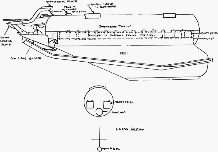 |
||
190. |
||
| Service tests were accomplished on a target developed by the James Russell Boiler Works, Boston, Massachusetts. This target simulates the swirl or crash dive of a submarine. It has been used by the 1st Sea Search Attack Group as an aid in training combat crews in attacking when only the swirl of a diving submarine is visible, and to select the correct point of release of 100 - pound practice bombs in relation to that swirl. It is also used in conjunction with ASV, odograph, and Searchlight developments. | ||
| The target, fabricated from iron boiler plate material, consists of a cylindrical hull rounded at each end, and two diving rudders. It is approximately fourteen feet long and two feet in diameter. It weighs 1,200 pounds, and it is actuated by means of a steel preformed cable attached to a towing winch. | ||
| The winch is a towing mechanism consisting of a reel for winding 3,000 feet of 3/16 inch galvanized flexible cable, mounted on a base and connected to a single cylinder 4 cycle gasoline engine with 7.8 horsepower rating at 1,800 revolutions per minute. | ||
| To operate this device it is towed at a distance of 300 to 1,000 yards maximum from the towing vessel at a speed of approximately 6 to 8 knots submerged. The diving rudders are actuated by the mechanism on the nose of the target. This mechanism is attached directly to the towing | ||
191. |
||
| cable in such a way that, when the towing cable is slackened momentarily with the target riding on the surface, water pressure causes the lower paddle to take charge and throw the diving rudder to the "dive position", at the same time extending the larger upper paddle. The same operation opens the air and fluid check valves, ejecting approximately one pint of specially dyed salt water soap solution out of the mixing valve in the tail until these valves are closed (at any desired interval) by the door check mounted on top of the target. The target then dives and remains in a submerged position until the tow wire is again slackened momentarily when the upper paddle takes charge and throws the diving rudders to the "up position" and the target comes to the surface, continuing to tow in this position until the cycle is again repeated. | ||
Test Data |
||
Tests: |
||
No. of flights - 3 Total flight time - 14:30 |
||
| (These were preliminary flights to test the feasibility of using the target. Planes of the Group and the 18th Antisubmarine Squadron at Langley Field accomplished training flights over the target. The training flight hours are incorporated in the training statistics and do not appear under test data.) | ||
No. hours target and boat were used for training and bombing flights - 51:30 |
||
Installation of equipment: |
||
No. military man hours - 12:00 |
||
Instructions: |
||
| No. military man hours -5:00 | ||
192. |
||
Total hours planes used on project: 14:30 |
||
Total man hours expended in installations and instructions: 17:00 |
||
SS #54 - MARKER SLICKS |
||
| This project was started 9 November, 1942, for the purpose of investigating various dye substances to determine comparative size, brilliancy, and duration of the spot made on open water, as a means of marking a particular spot, such as the location of a sonic radio buoy, a MAD contact, or the contour of a search pattern or trapping circle. Various colored dyes furnished by the DuPont Corporation were tested by this Group. A total of 68 different samples of dyes were dropped on the open sea. These 68 samples were chosen after elimination tests conducted by DuPont personnel. Of the samples dropped at Langley Field, two were found which gave satisfactory performance. | ||
| This Group recommended the use of flourescein or, alternatively, a mixture of flourescein and tatanium dioxide for antisubmarine work. Both of these slicks have a vivid green color much different from the green of the water and were found to be visible both in misty weather and in clear weather from ranges varying from 3/4 mile up to about 2-1/2 miles at an altitude of 300 feet. At an altitude of 1,000 feet these dyes could be seen at ranges in excess of five miles. The choice of these | ||
193. |
||
| particular slicks was based on opinions of several pilots and other observers from this Group. | ||
| It was recommended that these slicks be procured in quantities not less than 1,400 cubic centimeters and not greater than 1,500 cubic centimeters, packed in a suitable rectangular container not exceeding 3-3/8 inches by 3-3/8 inches by 11 inches. This particular size container was regarded as optimum for use in the automatic slick dropper (SS #16). | ||
| Subsequently tests on containers were accomplished and as papier-mache covering furnished by Wilsonite Corporation, New Jersey, proved to be superior to any other paper type container for use from a plane. The Wilsonite container shatters on contact with the water and throws the dye several feet in every direction; none of the dye is carried to the bottom. | ||
| The flourescein slicks in Wilsonite containers have proved to be a valuable accessory in flying MAD searches. They were used extensively in the Sea Search Exercises at Key West with satisfactory results. | ||
Test Data |
||
Tests: |
||
No. of flights - 6 Total flight time - 16:20 |
||
No. of slicks dropped: |
||
| Received 500 | ||
| Less inventory 100 | ||
| Expended 400 | ||
194. |
||
SS #55 - SEARCHLIGHTS |
||
| Comments under SS #14. | ||
SS #56 - RELOADABLE ROCKET GUN |
||
| Comments under SS #9. | ||
SS #57 - NIGHT PHOTOGRAPHIC EQUIPMENT FOR ANTISUBMARINE AIRCRAFT |
||
| As a result of tests and demonstrations of the High Altitude Stroboscopic Light conducted at Langley Field during December, 1942, a project was set up for the development of a modified light weight unit which would be suitable for low altitude night photography. | ||
| The Sea Search Photographic Unit is an electric flash machine for low altitude repetitive night photography. The unit furnishes illumination for a series of pictures from 300 to 500 feet. Control is accomplished by means of a contact built into a government furnished K-24 aerial camera. The curtains are removed from this camera, and it is three per second. The lamp and camera are side by side in a rotating mount to permit photographs to be taken of the target as the plane flies overhead. The entire operation of the equipment is controlled by the bombardier. | ||
195. |
||
| The flasher unit is self-contained and consists of a 24-volt motor alternator, a step-up transformer, and rectifier tubes to produce the necessary 3,500 volts direct current. This charges a condenser of 50 mfd. and also supplies the necessary power to operate a strobotron type pulse amplifier which controls the flashing of the lamp. | ||
| The installation of the unit is very simple and consists of fastening the reflector to the rotating camera mount and placing the power unit at any convenient place on the floor of the plane. The point of connection will depend entirely upon the type of plane used and the buss system available. However, any connection must be capable of supplying 150 amp. for a short time. | ||
| The operation of the unit is simple. The lamp assembly is permanently connected to the power unit with a large six-wire cable, and the only connections necessary are to the 24-volt plane's battery and the synchronizing connection to the K-24 camera. | ||
| This flasher unit was tested to determine its capabilities in proving sufficient illumination to record on photographic film at night any object from 500 feet or less. It was synchronized with the K-24 camera. Actual flight tests of the Sea Search Photographic Unit were commenced 4 April, 1943, and were continued through 4 June, 1943. These tests included recording simulated night bombing attacks on water targets as well as photographing land targets. | ||
196. |
||
| Results of testing show that this unit is practical for recording night antisubmarine activities when mounted with the cameras in a vertical position. However, this unit does not have sufficient power to illuminate the target throughout the traverse of the swinging mount. It was found that the bakelite socket which holds the flasher tube tends to absorb moisture and presents the possibility of a dangerous short circuit from the high voltage connection on the socket and stand bolt. By making a socket out of plexiglass this difficulty was overcome. | ||
| Pending the availability of a lighter weight Sea Search Unit being developed by Dr. Edgerton, it was recommended that the present flasher unit be adopted for aircraft engaged in night antisubmarine activity*. | ||
Test Data |
||
Tests: |
||
No. of flights - 7 Total flight time - 11:55 |
||
Installation of equipment: |
||
| No. military man hours - 4:00 No. plane hours - 172:00 | ||
Total hours planes used on project: 15:55 |
||
Total man hours expended in installations and instructions: 4:00 |
||
SS #58 - MAGNETIC TOW TARGET |
||
| This project was set up on 19 January, 1943, as the result of | ||
- - - - - - - - - - - - - - - - - - - - - - - - - - - - - - - - - - - - - - - - - - - - - - - - - - - - - - - - - - - - |
||
| * See Appendix 35 for detailed report on flasher unit. | ||
197. |
||
| a proposal to construct a modified version of the submersible tow target (SS #53) which would enable this new device to be used as a magnetic target in conjunction with MAD searches, MABS attacks, and further experiments with retro bombing. | ||
| Construction of a target according to specifications determined by members of this organization and Columbia Laboratory personnel was initiated. The main feature of this proposed target was a large magnetic core which set up a magnetic field around the target and approximates the magnetic field of a submarine. The coil design was to produce a magnetic moment of not less that 108 cgs. Eight round cores 4 inches in diameter by 7.5 feet long were to be mounted parallel on 8-inch centers, forming a square on 18-inch square bakelite endplates. The core material was to be hand puddled wrought iron treated to obtain the best magnetic properties. | ||
| Each core was to be wound with 50 pounds of #14 SCE copper wire in even layers. The length of the windings was to be 7 feet 4 inches. A length of shaft 1-inch long was to be left at each end of each core for mounting purposes. | ||
| Eight 12 V Exide type D-6 aircraft batteries were to be used to supply 106 volts for the operation of the coils. Connector lugs accessible externally from the two target were to be provided for changing the batteries. Inspection plates were to be provided to facilitate watering and changing of batteries. | ||
198. |
||
| This target was never received at this station because the 1st Sea Search Attack Group discontinued antisubmarine activities prior to its completion. However, it was turned over to the Navy where it will no doubt prove to be of considerable value in testing various magnetic devices being developed for antisubmarine warfare. | ||
| In addition to the tow target, a magnetic tow barge was constructed for training purposes at Langley Field. A barge of the Navy Mark IIA sweep (YS-121) type was obtained, which was equipped with an oval shaped coil mounted horizontally. The coil is approximately 38 feet long and 24 feet wide and contains 200 turns of 300,000 circular mill. copper cable. The mean radius of the coil is approximately 20,000 feet. The dc resistance of 0.74 ohms. The magnetic moment of the vertical dipole it produces with a terminal potential of 6 volts and a current of 8.1 amperes is approximately 1.2 x 10 to the eighth cgs. In using the barge in practice, it is usual to fly at an altitude of 100 feet above the water. While doing so, the magnetic barge is used to represent a submarine at a depth of 100 feet. A loop terminal potential of from 2 to 4 volts satisfies this condition for tactical practice. | ||
| A 6-volt battery of 120 ampere hour capacity is sufficient for several days of operation if the barge operator cuts the current off when no MAD airplanes are in sight. A large S.P.S.T. with a well insulated handle serves to protect the operator from high inductive | ||
199. |
||
| voltage generated when the coil circuit is opened. | ||
| The barge was used during the beginning of MAD tactical training to familiarize the airplane crews with the problems involved. | ||
| Normal timed radar "run-ins" were made on the barge, trapping circles were established, detections were made, and the clover leaf tracking procedure was employed to track and bomb the barge. The fact that the barge could be seen by the crew was probably an advantage during the first phase of MAD training, since the entire problem could be easily visualized by the pilot. The crew of course assumed that the barge was a submerged submarine as far as flying procedure was concerned. The pilot was guided entirely by the MAD operator and the navigator, neither of whom saw the barge. | ||
Test Data |
||
| No. of training flights accomplished in conjunction with MAD barge - 60 | ||
| Total flight hours - 66:24 | ||
SS #59 - LONG RANGE NAVIGATION EQUIPMENT |
||
| This project was initiated on 9 March, 1943, at the request of the Director of Technical Services to provide for flight tests of Lodar and LRN equipment and to train Army personnel in the operation and maintenance of these sets. | ||
200. |
||
| The first to be tested was Lodar, which is a type of navigational radio-direction finding equipment operating on 1950 Kc. It is essentially a radio compass using the loop antenna, and its use is similar to the standard radio compass with the exception that bearings are taken on special navigational beacons rather than on broadcasting stations, range station and so forth. Similar to the radio compass, it can be used for either obtaining fixes by using a pair of stations or for homing. | ||
| The main purpose of the tests which were conducted during the period 24 March, 1943, to 29 March, 1943, was to determine the effective ranges of the Lodar receiver over land and over water. Satisfactory results were obtained with consistent over-land ranges of approximately 100 miles and over-water ranges of about 300 miles. | ||
| As a homing device it was determined that Lodar was accurate within 5 or 6 degrees, and as a navigational aid in obtaining fixes its accuracy was equivalent to other navigational methods. | ||
Test Data |
||
Tests: |
||
No. of flights - 7 Total flight time - 21:25 |
||
Installation of equipment: |
||
| No. civilian man hours - 4:00 Total plane hours - 4:00 | ||
Instructions: None |
||
201. |
||
| Total hours planes used on project: 25:25 | ||
Total man hours expended in installations and instructions: 4:00 |
||
| On 4 April, 1943, tests of LRN (SCR-722) were undertaken by the 1st Sea Search Attack Group in conjunction with personnel from A.R.L. LRN is a type of Navigational equipment utilizing a time delay between transmissions from a master and a slave station to determine the position of the receiver. Stations are specially constructed beacons located at approximate positions along the coast. | ||
| The equipment consists of a radio receiver capable of receiving the transmission and an indicator which incorporates an oscilloscope to determine the line of position that the receiver is on. By use of two pairs of stations two intersection lines of position may be obtained. | ||
| One purpose of these flight tests was to measure the characteristics of the trailing wire antenna in type B-24 airplanes and to develop a suitable radio frequency transformer to match the antenna to SCR-722 (LRN) in order to obtain a better signal strength. Sufficient data was collected so that the desired modification of the set could be accomplished. At the same time the A.R.L. personnel instructed a limited number of Sea Search navigators and radio mechanics in the operation and maintenance of this equipment. The personnel thus instructed have since trained others in the operation and maintenance of LRN. | ||
202. |
||
Test Data |
||
Tests: |
||
No. of flights - 8 Total flight time - 18:50 |
||
No. of ground tests - 2 Total ground time - 4:30 |
||
Installation of equipment: None |
||
Instructions: |
||
| No. civilian man hours - 16:00 | ||
| Total hours planes used on project: 23:20 | ||
Total man hours expended in installations and instructions: 16:00 |
||
SS #60 - ARMAMENT FOR ANTISUBMARINE AIRCRAFT |
||
| This project was opened on 12 February, 1943, as a result of the proposal that a 37 mm. cannon be installed in the nose of a B-24. No action took place at this station, and the file has been used as a catch-all for related information, such a bomb capacities under various loading conditions and information regarding a .50 caliber flexible gun installation for the side door of a B-18B. | ||
SS #61 - RADIO MARKER BUOY |
||
| This project was opened on 2 March, 1943, by this Group and is concerned with two radio marker buoys which are transmitter buoys on which a plane can home with the radio compass. One of these buoys | ||
203. |
||
| was developed by the Aircraft Radio Laboratory, Wright Field, and another by the Howard Hughes Aircraft Corporation. | ||
| It was anticipated that the buoys would be used to mark a spot on the ocean to which a search airplane could return or to which it could direct assisting airplanes. It was also suggested that it could possibly be used as an emergency marker in the event of forces landings at sea. | ||
| Preliminary tests were conducted on models of both type buoys during March, 1943. Data on ranges and the results of dropping the buoys from 1,000 feet was accumulated in order that necessary improvements could be incorporated in additional experimental models. | ||
| Tests on subsequent models were again conducted by Aircraft Radio Laboratory personnel at Langley Field during June. A range up to 67 miles was obtained on the Wells-Gardner buoy, and a range of 20 miles on the Hughes buoy on frequencies from 1625 to 1645 kc. | ||
| As a result of information gathered during the previous testing of the two types of buoys, a preproduction model is in its final development stage at Wright Field, and it is anticipated that this model will be tested at Langley Field. This buoy is 6 inches by 54 inches in size and weighs 31 - 33 pounds. A 75 mile range is anticipated, operating on a frequency band of 450 to 540 kc. It has a six foot cotton baseball type parachute with a 30 foot static line between chute and buoy. | ||
204. |
||||||||||
Test Data |
||||||||||
Tests: |
||||||||||
No. of flights - 30 Total flight time - 45:10 |
||||||||||
Installation of equipment: None |
||||||||||
Instructions: None |
||||||||||
Total hours planes used on project: 45:10 |
||||||||||
SS #62 - LOW POWER PORTABLE BEACON |
||||||||||
| Testing of this beacon, which was developed by the Radiation Laboratory, M.I.T., started 17 February, 1943, at the request of the Director of Technical Services. | ||||||||||
| The low power beacon, using a lighthouse tube for a transmitter and a wide band crystal video receiver, has been tested with the antenna mounted both high and low. During the tests using an antenna mounted as high as possible (about 100 feet above the ground), a biconical horn antenna having a gain of about five was used. The following ranges listed are the average of the several maximum ranges obtained in the different tests at the required altitudes: | ||||||||||
|
||||||||||
| If the linear-array antenna having a gain of about twenty-five were | ||||||||||
205. |
||||||||||
| used at the same mounting height, the above ranges would be somewhat increased. | ||||||||||
| The beacon was also tested using a linear-array antenna having a gain of about twenty-five and mounted about twelve feet above the ground. The average of the maximum ranges obtained at the different altitudes are given below: | ||||||||||
|
||||||||||
| No difference was noted between the ranges observed over flat terrain and the ranges observed over water. | ||||||||||
| Tests were also conducted to determine the maximum number of planes that can simultaneously interrogate the beacon, and it was found that, if the planes have a 400 cycle recurrence rate when switched for beacon operation, the beacon handles a maximum of three planes whose spinners are constantly directed toward the beacon. If the planes interrogate the beacon only when scanning with the spinner, a large number of planes (probably 15 or 20 or more) can satisfactorily receive the beacon. If the beacon is over-interrogated, the relay system will turn off the high voltage section of the modulator. The beacon may again be put into operation by the manual operation of the reset button. The relays will not react to momentary surges. | ||||||||||
206. |
||
| Tests were also conducted to determine the usefulness of these low power beacons as runway locators for approaches through heavy overcast. However, because of the very limited time during which three beacons were available at Langley Field, the result cannot be considered as conclusive. Nevertheless it was found that the radar operator employing the 20-mile sweep could successfully guide the pilot over the runway and give an accurate estimate of its position and distance. No actual let-downs under instrument conditions were accomplished before the beacons were released for overseas shipment, but it was believed that they could have been accomplished had there been sufficient time to develop the necessary technique for such approaches. | ||
Test Data |
||
Tests: |
||
No. of flights - 16 Total flight time - 31:50 |
||
Installation of equipment: None |
||
Instructions: |
||
| No. civilian man hours - 34:00 | ||
Total hours planes used on project: 31:50 |
||
Total man hours expended in installations and instructions: 34:00 |
||
| The reader of this history is again advised to consult the project envelopes now filed with the AAF historian if more detailed technical information in regard to the foregoing is desired. | ||